Published: 11-May-2011 Engine System - General Information - General specifications 2.0 litre diesel. Item Specification Code FMBA/FMBB Firing order 1-3-4-2 Cylinder bore diameter 86 mm Stroke 86 mm Displacement 1998 cc Compression ratio 19:1 Engine weight 195 kg (excluding front end accessory drive) Power output at 3800 rpm 96 kW (130 PS) Torque at 1800 rpm 325 Nm Idle speed 900 rpm General specifications 2.2 litre diesel. Item Specification Code QJBA Firing order 1-3-4-2 Cylinder bore diameter 86 mm Stroke 94.6 mm Displacement 2198 cc Compression ratio 19:1 Power output at 3800 rpm 114 kW (155 PS) Torque at 1800 rpm 360 Nm Idle speed 800 rpm General specifications 2.0 litre. Item Specification Displacement in liters 2.099 Number of cylinders 6 Bore and stroke (mm) 81.6 x 66.84 Firing order 1,4,2,5,3,6 Compression ratio 10.75:1 General specifications 2.5 litre. Item Specification Displacement in liters 2.495 Number of cylinders 6 Bore and stroke (mm) 81.6 x 79.5 Firing order 1,4,2,5,3,6 Compression ratio 10.3:1 General specifications 3.0 litre. Item Specification Displacement in liters 2.967 Number of cylinders 6 Bore and stroke (mm) 89.0 x 79.5 Firing order 1,4,2,5,3,6 Compression ratio 10.5:1 Cylinder Block Dimensions 2.0 litre and 2.2 litre diesel. Description mm Cylinder bore diameter – Class 1 86·000 - 86·010 Cylinder bore diameter – Class 2 86·010 - 86·020 Cylinder bore diameter – Class 3 86·020 - 86·030 Main bearing shells 1 to 4 – inside diameter (bearings installed) 65·003 - 65·030 Main bearing shells 5 – inside diameter (bearings installed) 70·004 - 70·033 Main bearings 1 to 4 – radial clearance 0·033 - 0·080 Main bearing 5 – radial clearance 0·034 - 0·083 Main bearings 1 to 4 – parent bore diameter – vertical measurement 64·504 - 64·520 Main bearing 5 – parent bore diameter – vertical measurement 74·504 - 74·520 Main bearings 1 to 4 – parent bore diameter – horizontal measurement 69·502 - 69·525 Main bearing 5 – parent bore diameter – horizontal measurement 74·502 - 74·525 Piston Dimensions 2.0 litre and 2.2 litre diesel. Description mm Piston cooling code 6 Piston diameter – Class A 85·94 - 85·95 Piston diameter – Class B 85·95 - 85·96 Piston diameter – Class C 85·96 - 85·97 Piston clearance in cylinder 0·05 - 0·07 Piston ring gap – piston ring installed 2.0 litre and 2.2 litre diesel. Description mm Upper compression ring 0·25 - 0·50 Lower compression ring 0·50 - 0·75 Oil scraper ring 0·25 - 0·40 Piston ring gap position: Distribute the piston ring gaps evenly around the circumference of the piston. This also applies to the oil control scraper ring elements. Position the ring gaps offset at 120 degrees to one another. Piston Pin Dimensions 2.0 litre and 2.2 litre diesel. Description mm Piston pin - length 66·700 Piston pin – diameter 30·000 Piston pin - clearance in piston pin bore 0·002 - 0·012
Crankshaft Dimensions 2.0 litre and 2.2 litre diesel. Description mm Main bearing journal – diameter 69·950 - 69·970 Main bearing journal – end float 0·090 - 0·305 Big-end bearing journal – diameter 52·980 - 53·000 Main bearing journals 1 to 4 – diameter 64·950 - 64·970 Connecting Rod Dimensions 2.0 litre and 2.2 litre diesel. Description mm Big-end bore – diameter 55·996 - 56·016 Small-end bore – diameter 30·010 - 30·018 Bid-end bearing shell – inside diameter (bearings installed) - Vehicle with 2.0L diesel engine 56·004 - 56·032 Bid-end bearing shell – inside diameter (bearings installed) - Vehicle with 2.2L diesel engine 53·034 - 53·080 Big-end bearing – radial clearance 0·034 - 0·100 Big-end bearing – end float 0·100 - 0·320 Camshaft Dimensions 2.0 litre and 2.2 litre diesel. Description mm Camshaft bearing journal – diameter 26·450 Camshaft bearing clearance – radial measurement 0·065 Camshaft – end float 0·125 Valves 2.0 litre and 2.2 litre diesel. Description mm Valve stem to valve guide clearance – intake valve 0·045 Valve stem to valve guide clearance – exhaust valve 0·055 Cylinder Head 2.0 litre and 2.2 litre diesel. Description mm Thickness of cylinder head gasket with piston protrusion of 0·430 - 0·520 mm 1·10 (1 hole/tooth) Thickness of cylinder head gasket with piston protrusion of 0·521 - 0·570 mm 1·15 (2 holes/teeth) Thickness of cylinder head gasket with piston protrusion of 0·571 - 0·620 mm 1·20 (3 holes/teeth) Maximum longitudinal/diagonal distortion of cylinder head surface 0·100 Peak to valley height of mating surface 0·020 Cylinder Head and Valve Train 2.0 litre. Item Specification Valve guide inner diameter (mm) 5.514 - 5.544 Intake valve effective length (mm) 91.13 - 90.93 Exhaust valve effective length (mm) 89.88 - 89.68 Valve stem to guide clearance intake - diameter (mm) 0.067 - 0.022 Valve stem to guide clearance exhaust - diameter (mm) 0.080 - 0.035 Valve head diameter intake (mm) 30.15 - 29.85 Valve head diameter exhaust (mm) 26.15 - 25.85 Intake valve face angle degree 45.75° Exhaust valve face angle degree 45.25° Valve stem diameter intake (mm) 5.492 - 5.477 Valve stem diameter exhaust (mm) 5.479 - 5.464 Valve spring free length (mm) 44.2 Valve spring installed height (mm) 33.41 Camshaft lobe lift intake (mm) 8.876 Camshaft lobe lift exhaust (mm) 8.876 Camshaft end play (mm) 0.150 - 0.070 Camshaft journal to cylinder head bearing surface clearance diameter (mm) 0.076 - 0.025 Camshaft journal diameter standard runout limit (mm) 0.040 Camshaft journal diameter standard out of round (mm) 0.013 Cylinder Head and Valve Train 2.5 litre. Item Specification Valve guide inner diameter (mm) 5.514 - 5.544 Intake valve effective length (mm) 91.13 - 90.93 Exhaust valve effective length (mm) 89.88 - 89.68 Valve stem to guide clearance intake - diameter (mm) 0.067 - 0.022 Valve stem to guide clearance exhaust - diameter (mm) 0.080 - 0.035 Valve head diameter intake (mm) 30.15 - 29.85 Valve head diameter exhaust (mm) 26.15 - 25.85 Intake valve face angle degree 45.75° Exhaust valve face angle degree 45.25° Valve stem diameter intake (mm) 5.492 - 5.477 Valve stem diameter exhaust (mm) 5.479 - 5.464 Valve spring free length (mm) 44.2 Valve spring installed height (mm) 33.41 Camshaft lobe lift intake (mm) 9.367 Camshaft lobe lift exhaust (mm) 9.461 Camshaft end play (mm) 0.150 - 0.070 Camshaft journal to cylinder head bearing surface clearance diameter (mm) 0.076 - 0.025 Camshaft journal diameter standard runout limit (mm) 0.040 Camshaft journal diameter standard out of round (mm) 0.013 Cylinder Head and Valve Train 3.0 litre. Item Specification Valve guide inner diameter (mm) 5.514 - 5.544 Intake valve effective length (mm) 91.13 - 90.93 Exhaust valve effective length (mm) 89.88 - 89.68 Valve stem to guide clearance intake - diameter (mm) 0.067 - 0.022 Valve stem to guide clearance exhaust - diameter (mm) 0.080 - 0.035 Valve head diameter intake (mm) 35.15 - 34.85
Item Specification Valve head diameter exhaust (mm) 30.15 - 29.85 Intake valve face angle degree 45.75° Exhaust valve face angle degree 45.25° Valve stem diameter intake (mm) 5.492 - 5.477 Valve stem diameter exhaust (mm) 5.479 - 5.464 Valve spring free length (mm) 44.2 Valve spring installed height (mm) 33.41 Camshaft lobe lift intake (mm) 9.367 Camshaft lobe lift exhaust (mm) 9.461 Camshaft end play (mm) 0.150 - 0.070 Camshaft journal to cylinder head bearing surface clearance diameter (mm) 0.076 - 0.025 Camshaft journal diameter standard runout limit (mm) 0.040 Camshaft journal diameter standard out of round (mm) 0.013 Lubrication system 2.0 litre and 2.2 litre diesel. Item Liters Oil capacity with filter 6.7 Lubrication system 2.0, 2.5 and 3.0 litre. Item Liters Oil capacity with filter 6.5
Published: 11-May-2011 Engine System - General Information - Engine Description and Operation 2.0L, 2.5L and 3.0L Engines The 2.0L, 2.5L and 3.0L engines consists of: A six cylinder 60 degree 'V' configuration liquid cooled aluminium cylinder block with dry cast iron liners. Aluminium pistons with cut-outs in the piston crown to clear the valve heads for any available combination of camshaft profile and valve phasing. Two aluminium cylinder heads with square squish chambers. Two cast iron overhead camshafts per bank. Four valves per cylinder. Mechanical tappets and top mounted steel shims. Continuous variable camshaft timing (VCT) of the inlet camshafts. Two silent timing chains with one hydraulic tensioner per chain. Magnesium alloy camshaft covers with rubber seals. A variable intake system containing two electrically controlled intake manifold tuning valves. Plastic lower intake manifold with integral fuel rail and injectors. Aluminium timing cover which accommodates the crankshaft front oil seal. An oil pump mounted around the crankshaft. An aluminium bed plate. An aluminium oil pan. A steel crankshaft (2.5L and 3.0L engines only). A cast iron crankshaft (2.0L engines only). Fracture-split connecting rods in sintered-forged steel. A single, six ribbed vee belt drives the front end accessories. A water pump belt pulley mounted directly to the exhaust camshaft of the left-hand cylinder head. A single, three ribbed vee belt which drives the water pump. A water pump mounted on the rear of the left-hand cylinder head. An advanced engine management system incorporating electronic throttle control. The unit meets the requirements of the CARB OBDII USA legislation. CAUTION: The use of supplementary oil or fuel additives is not approved unless specified by Jaguar cars in the form of a service communication or directive. The engine code and serial number is located on the left-hand side of the bed plate near the oil cooler assembly. 2.0L and 2.2L common rail diesel engine The 2.0L and 2.2L common rail diesel engine consists of: a four cylinder cast iron cylinder block a aluminium cylinder head a separate camshaft carrier a forged steel crankshaft with eight counterweights lightweight aluminium alloy pistons fracture split connecting rods a multi link drive chain which drives the camshafts and the high pressure pump a single link chain which drives a gear-type oil pump hydraulically operated timing chain tensioner fabricated camshafts with sintered lobes roller rocker valve actuation two exhaust valves and two inlet valves per cylinder a plastic composite camshaft cover a pressed steel timing cover which must be aligned using the special tool a engine oil cooler is mounted to the left hand side of the engine a water pump is mounted to the left hand rear of the engine and driven via the rear of the power steering pump a power steering pump is mounted to the left hand rear of the engine and driven by the rear of the intake camshaft via a multi-vee belt a variable vain turbocharger.
* * * * * * * * * * * * * * * * * * * * * * * * * * * * * * * * * * * * * * * * * * * * * * * * * * * * * * * * * * * * * * * * * * * * Published: 11-May-2011 Engine System - General Information - Engine Diagnosis and Testing Inspection and Verification Since diagnosis and testing actually begins when repairs are taken on, the following procedure is recommended. 1. Verify the customer concern by operating the system. 1. 2. Visually inspect for obvious signs of mechanical damage or electrical damage. If the concern cannot be reproduced, carry out a road test and/or visual check with the aid of the following table. Visual Inspection Chart Mechanical Coolant leaks Oil leaks Leaks in the fuel system Visibly damaged or worn parts Loose or missing nuts or bolts 2. 3. If an obvious cause for an observed or reported concern is found, correct the cause (if possible) before proceeding to the next step. 3. 4. If the concern is not visually evident, verify the symptom and refer to the Symptom Chart. 4. Symptom Chart Symptom Chart Symptom Possible Sources Action Difficult to start during hot or cold start Piston ring(s) worn, damaged, sticking or worn piston/cylinder. INSTALL a new engine. Head gasket damaged. INSPECT the head gasket. Fuel system damaged or inoperative. For additional information, refer to Section 303-04A Fuel Charging and ControlsSection 303-04B Fuel Charging and ControlsSection 303-04C Fuel Charging and Controls - Turbocharger. Ignition system inoperative. For additional information, refer to Section 303-04A Fuel Charging and ControlsSection 303-04B Fuel Charging and ControlsSection 303-04C Fuel Charging and Controls - Turbocharger. Poor Idling Restricted exhaust system. INSPECT the exhaust system. For additional information, refer to Section 309-00 Exhaust System. Vacuum leak. CARRY out the Intake Manifold Vacuum Test in this section. REPAIR and INSTALL new components as necessary. Burned valve(s). INSPECT the valve(s). Incorrect valve to valve seat contact. INSPECT the valve and valve seat. Head gasket damaged. INSPECT the head gasket. Fuel system damaged or inoperative. For additional information, refer to Section 303-04A Fuel Charging and ControlsSection 303-04B Fuel Charging and ControlsSection 303-04C Fuel Charging and Controls - Turbocharger. Insufficient power Compression leakage from valve seat. INSPECT the valve or valve seat. Valve sticking. INSPECT valve stem to valve guide clearance or carbon accumulation. Valve spring weak or broken. INSPECT the valve spring. Head gasket damaged. INSPECT the head gasket. Cylinder head cracked or distorted. INSPECT the cylinder head. Piston ring(s) worn, damaged or sticking. INSTALL a new engine. Fuel system damaged or inoperative. For additional information, refer to Section 303-04A Fuel Charging and ControlsSection 303-04B Fuel Charging and ControlsSection 303-04C Fuel Charging and Controls - Turbocharger. Brakes dragging. For additional information, refer to Section 206-00 Brake System - General Information. Restricted exhaust system. INSPECT the exhaust system. For additional information, refer to Section 309-00 Exhaust System. Excessive or insufficient compression. Valve(s) burnt or sticking. INSPECT the valve(s). Valve spring(s) weak or broken. INSPECT the valve spring(s). Piston ring(s) worn, damaged, sticking or worn piston/cylinder. INSTALL a new engine. Head gasket damaged. INSPECT the head gasket. Carbon accumulation in combustion chamber. ELIMINATE carbon build up. Fuel system damaged or inoperative. For additional information, refer to Section 303-04A Fuel Charging and ControlsSection 303-04B Fuel Charging and ControlsSection 303-04C Fuel Charging and Controls - Turbocharger. Excessive oil consumption Piston ring(s) worn, damaged, sticking or worn piston/cylinder. INSTALL a new engine. Valve stem seal worn or missing. INSPECT the valve or valve stem seal. Oil leakage. REPAIR oil leakage. Valve stem or valve guide worn. INSPECT the valve stem or valve guide. Incorrect oil viscosity. DRAIN and FILL with new oil. Diluted oil. CHECK oil dilution. DRAIN and FILL as necessary. Crankcase overfilled. CHECK and adjust the oil level. Incorrect oil pressure. CHECK the oil pressure. REPAIR as necessary. Engine noise Excessive crankshaft main bearing clearance. INSTALL a new engine.
* * * * * * * * * * * * * * * * * * * * * * * * * * * * Excessive crankshaft end play. INSTALL a new engine. Excessive connecting rod bearing oil clearance. INSTALL a new engine. Piston/cylinder worn. INSTALL a new engine. Piston ring damaged. INSTALL a new engine. Connecting rod bent. INSTALL a new engine. Valve spring(s) broken. INSPECT the valve spring(s). Excessive valve guide clearance. INSPECT the valve guide or valve. Cooling system inoperative (water pump, vibration of radiator). For additional information, refer to Section 303-03A Engine CoolingSection 303-03B Engine Cooling. Fuel system inoperative. For additional information, refer to Section 303-04A Fuel Charging and ControlsSection 303-04B Fuel Charging and ControlsSection 303-04C Fuel Charging and Controls - Turbocharger. Excessive carbon buildup. ELIMINATE carbon buildup. Exhaust gas leakage. REPAIR leakage. For additional information, refer to Section 309-00 Exhaust System. Incorrect drive belt tension. INSPECT the drive belt tension. For additional information, refer to Section 303-05 Accessory Drive. Generator front bearing worn. For additional information, refer to Section 414-02 Generator and Regulator. Tappet noise, engine running Incorrect tappet clearance. CHECK and ADJUST the tappet clearance as necessary. Component Tests Engine Oil Leaks • NOTE: Before installing new gaskets or oil seals, make sure that the fault is clearly established. If the oil leak cannot be identified clearly by a visual inspection, carry out an UV test: Fluorescent Oil Additive Method 1. Clean the engine with a suitable cleaning fluid (brake cleaner). 1. 2. Drain the engine oil and refill with recommended oil, premixed with Diesel Engine Oil Dye or equivalent. Use a minimum 14.8 ml (0.5 ounce) to a maximum 29.6 ml (1 ounce) of fluorescent additive to all engines. If oil is not premixed, fluorescent additive must first be added to the crankcase. 2. 3. Run engine for 15 minutes. Stop the engine and inspect all seal and gasket areas for leaks using a 12 Volt Master UV Diagnostic Inspection Kit or equivalent. A clear bright yellow or orange area will identify leak. For extremely small leaks, several hours may be required for the leak to appear. 3. 4. As necessary, pressurize the main oil gallery system to locate leaks due to incorrectly sealed, loose or cocked plugs. 4. 5. Repair all leaks as necessary. 5. Compression Test General Remarks • NOTE: Removing fuses and disconnecting electrical components causes the engine control module (ECM) to log an error message. After the measurements have been carried out this error message should be cleared from memory by connecting to approved Jaguar diagnostic system. • NOTE: Only check the compression pressure with the valves set to the prescribed clearance (if this can be adjusted). The compression pressure should be checked with the engine at operating temperature. Check The Compression Pressure WARNING: On manual transmissions shift the transmission into neutral. On automatic transmission vehicles, select "P". Failure to follow these instructions may result in personal injury. 1. Remove the fuel pump relay. 1. 2. Start the engine - the engine will start, run for a few seconds then stall. 2. 3. Remove the spark plugs. 3. 4. Install the compression tester. 4. 5. Install an auxiliary starter switch in the starting circuit. With the ignition switch OFF, using the auxiliary starter switch, crank the engine a minimum of five compression strokes and record the highest reading. Note the approximate number of compression strokes required to obtain the highest reading. 5. 6. Repeat the test on each cylinder, cranking the engine approximately the same number of compression strokes. 6. 7. Install the components in reverse order, observing the specified tightening torques. 7. 8. Reset the ECM fault memory. 8. Interpretation of the Results The indicated compression pressure are considered within specification if the lowest reading cylinder is within 75% of the highest reading. CAUTION: If engine oil is sprayed into the combustion chamber, after carrying out the measurement run the engine at 2000 rpm for about 15 minutes, in order to burn the oil and prevent damage to the catalytic converter. If the measurement on one or more cylinders is much lower than the specified value, spray some engine oil into the combustion chamber
and repeat the compression measurement. If the reading greatly improves then the piston rings are damaged. If the reading stays the same then the cause is either damaged valve seats or valve stem seals. If the measurements for two cylinders next to each other are both too low then it is very likely that the cylinder head gasket between them is burnt through. This can also be recognized by traces of engine oil in the coolant and/or coolant in the engine oil. Excessive Engine Oil Consumption The amount of oil an engine uses will vary with the way the vehicle is driven in addition to normal engine-to-engine variation. This is especially true during the first 16,100 km (10,000 miles) when a new engine is being broken in or until certain internal components become conditioned. Vehicles used in heavy-duty operation may use more oil. The following are examples of heavy-duty operation: Trailer towing applications. Severe loading applications. Sustained high speed operation. Engines need oil to lubricate the following internal components: Cylinder block cylinder walls. Pistons and piston rings. Intake and exhaust valve stems. Intake and exhaust valve guides. All internal engine components. When the pistons move downward, a thin film of oil is left on the cylinder walls. As the vehicle is operated, some oil is also drawn into the combustion chambers past the intake and exhaust valve stem seals and burned. The following is a partial list of conditions that can affect oil consumption rates: Engine size. Operator driving habits. Ambient temperatures. Quality and viscosity of oil. Operation under varying conditions can frequently be misleading. A vehicle that has been run for several thousand miles on short trips or in below-freezing ambient temperatures may have consumed a "normal" amount of oil. However, when checking the engine oil level, it may measure up to the full mark on the oil level indicator due to dilution (condensation and fuel) in the engine crankcase. The vehicle then might be driven at high speeds on the highway where the condensation and fuel boil off. The next time the engine oil is checked it may appear that a liter of oil was used in about 160 km (100 miles) per liter oil consumption rate is about 2,400 km (1,500 miles) per liter. Make sure the selected engine oil meets Jaguar specification and the recommended API performance category "SG" and SAE viscosity grade as shown in the vehicle Owner's Guide. It is also important that the engine oil is changed at the intervals specified for the typical operating conditions. Oil Consumption Test The following diagnostic procedure is used to determine the source of excessive oil consumption. • NOTE: Oil use is normally greater during the first 16,100 km (10,000 miles) of service. As mileage increases, oil use decreases. Vehicles in normal service should get a least 16,000 km (10,000 miles) per liter. High speed driving, towing, high ambient temperature and other factors may result in greater oil use. 1. Define excessive consumption, such as the number of miles driven per liter of oil used. Also determine customers's driving habits, such as sustained high speed operation, towing, extended idle and other considerations. 1. 2. Verify that the engine has no external oil leaks as described under Engine Oil Leaks. 2. 3. Verify that the engine has the correct oil level. 3. 4. Verify that the engine is not being run in an overfilled condition. Check the oil level at least five minutes after a hot shutdown with the vehicle parked on a level surface. In no case should the level be above the top of the cross-hatched area and the letter "F" in FULL. If significantly overfilled, carry out step 5, sub steps 1 through 4. 4. 5. Carry out an oil consumption test: 1. Drain engine oil and fill with one liter less than the recommended amount. 2. Run the engine for three minutes (10 minutes if cold), and allow oil to drain back for at least five minutes with vehicle parked on level surface. 3. Remove the oil level indicator and wipe clean. (Do not wipe with anything contaminated with silicone compounds.) Install the oil level indicator making sure to seat the oil level indicator firmly in the oil level indicator tube. Remove the oil level indicator and draw a mark on the back (unmarked) surface at the indicated oil level. (This level should be about the same as the ADD mark on the face of the oil level indicator.) 4. Add one liter of oil. Start the engine and allow to idle for at least two minutes. Shut off the engine and allow the engine oil to drain back for at least five minutes. Mark the oil level dipstick, using the procedure above. (This level may range from slightly below the top of the cross-hatched area to slightly below the letter "F" in FULL. 5. Record the vehicles mileage. 6. Instruct the customer to drive the vehicle as usual and: 1. Check the oil level regularly at intervals of 160-240 km (100-150 miles). 2. Return to the service point when the oil level drops below the lower (ADD) mark on the oil level indicator. 3. Add only full liters of the same oil in an emergency. Note the mileage at which the oil is added. 7. Check the oil level under the same conditions and at the same location as in steps 3 and 4. 1. Measure the distance from the oil level to the UPPER mark on the oil level indicator and record. 2. Measure the distance between the two scribe marks and record. 3. Divide the first measurement by the second. 4. Divide the distance driven during the oil test by the result. This quantity is the approximate oil consumption rate in kilometers per liter or in mile per quart. 5.
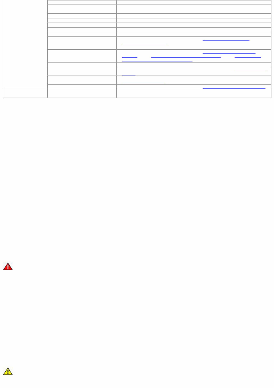
5. If the oil consumption rate is unacceptable go to Step 6. 6. Check the positive crankcase ventilation (PCV) system. Make sure the system is not plugged. 6. 7. Check for plugged oil drain-back holes in the cylinder head and cylinder block. 7. 8. If the condition still exists after carrying out the above tests go to step 9. 8. 9. Carry out a cylinder compression test. Refer to the procedure in this section : Compression Test. This can help determine the source of oil consumption such as valves, piston rings or other areas. 9. 10. Check valve guides for excessive guide clearance. Install new valve stem seals after verifying valve guide clearance. 10. 11. Worn or damaged internal engine components can cause excessive oil consumption. Small deposits of oil on the tips of the spark plugs can be a clue to internal oil consumption. 11. Intake Manifold Vacuum Test Bring the engine to normal operating temperature. Connect a vacuum gauge or equivalent to the intake manifold. Run the engine at the specified idle speed. The vacuum gauge should read between 51-74 kPa (15-22 in-Hg) depending upon the engine condition and the altitude at which the test is performed. Subtract 4.0193 kPa (1 in-Hg) from the specified reading for every 304.8 m (1,000 feet) of elevation above sea level. The reading should be steady. As necessary, adjust the gauge damper control (where used) if the needle is fluttering rapidly. Adjust the damper until the needle moves easily without excessive flutter. Interpreting Vacuum Gauge Readings A careful study of the vacuum gauge reading while the engine is idling will help pinpoint trouble areas. Always conduct other appropriate tests before arriving at a final diagnostic decision. Vacuum gauge readings, although helpful, must be interpreted carefully. Most vacuum gauges have a normal band indicated on the gauge face. The following are potential gauge readings. Some are normal; others should be investigated further. 1. NORMAL READING: Needle between 51-74 kPa (15-22 in-Hg) and holding steady. 1. 2. NORMAL READING DURING RAPID ACCELERATION : When the engine is rapidly accelerated (dotted needle), the needle will drop to a low (not to zero) reading. When the throttle is suddenly released, the needle will snap back up to a higher than normal figure. 2. 3. NORMAL FOR HIGH-LIFT CAMSHAFT WITH LARGE OVERLAP: The needle will register as low as 51 kPa (15 in-Hg) but will be relatively steady. Some oscillation is normal. 3. 4. WORN RINGS OR DILUTED OIL: When the engine is accelerated (dotted needle), the needle drops to 0 kPa (0 in-Hg). Upon deceleration, the needle runs slightly above 74 kPa (22 in-Hg). 4. 5. STICKING VALVES: When the needle (dotted) remains steady at a normal vacuum but occasionally flicks (sharp, fast movement) down and back about 13 kPa (4 in-Hg), one or more valves may be sticking. 5. 6. BURNED OR BENT VALVES: A regular, evenly-spaced, downscale flicking of the needle indicates one or more burned or damaged valves. Insufficient hydraulic valve tappet or hydraulic lash adjuster clearance will also cause this reaction. 6. 7. POOR VALVE SEATING: A small but regular downscale flicking can mean one or more valves are not seating correctly. 7. 8. WORN VALVE GUIDES: When the needle oscillates over about a 13 kPa (4 in-Hg) range at idle speed, the valve guides could be worn. As engine speed increases, the needle will become steady if guides are responsible. 8. 9. WEAK VALVE SPRINGS: When the needle oscillation becomes more violent as engine RPM is increased, weak valve springs are 9.
indicated. The reading at idle could be relatively steady. 10. LATE VALVE TIMING: A steady but low reading could be caused by late valve timing. 10. 11. IGNITION TIMING RETARDING: Retarded ignition timing will produce a steady but somewhat low reading. 11. 12. INSUFFICIENT SPARK PLUG GAP: When spark plugs are gapped too close, a regular, small pulsation of the needle can occur. 12. 13. INTAKE LEAK: A low, steady reading can be caused by an intake manifold or throttle body gasket leak. 13. 14. BLOWN HEAD GASKET: A regular drop of fair magnitude can be caused by a blown head gasket or warped cylinder head to cylinder block surface. 14. 15. RESTRICTED EXHAUST SYSTEM: When the engine is first started and is idled, the reading may be normal, but as the engine rpm is increased, the back pressure caused by a clogged muffler, kinked tail pipe or other concerns will cause the needle to slowly drop to 0 kPa (0 in-Hg). The needle then may slowly rise. Excessive exhaust clogging will cause the needle to drop to a low point even if the engine is only idling. 15. When vacuum leaks are indicated, search out and correct the cause. Excess air leaking into the system will upset the fuel mixture and cause concerns such as rough idle, missing on acceleration or burned valves. If the leak exists in an accessory such as the power brake booster, the unit will not function correctly. Always repair vacuum leaks.
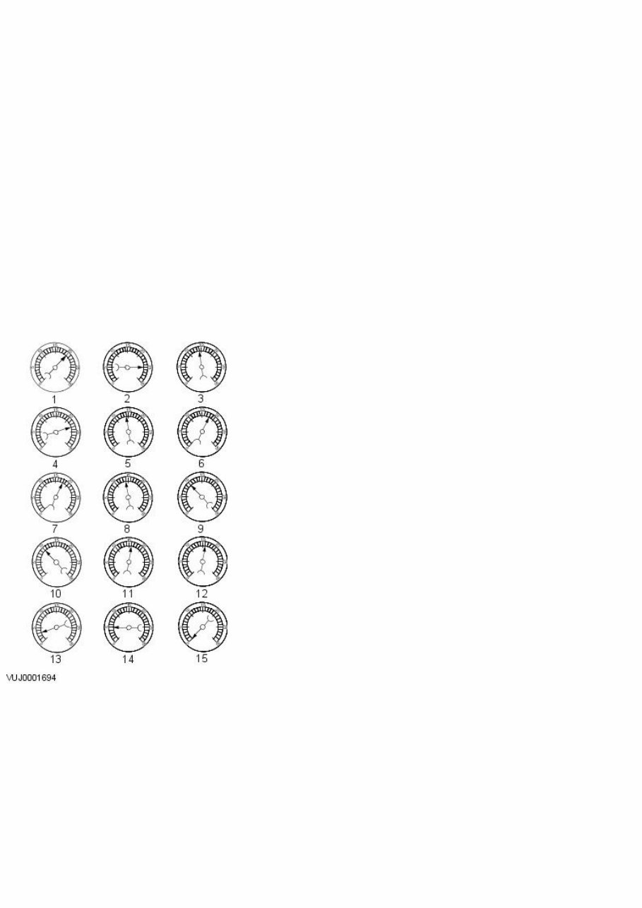
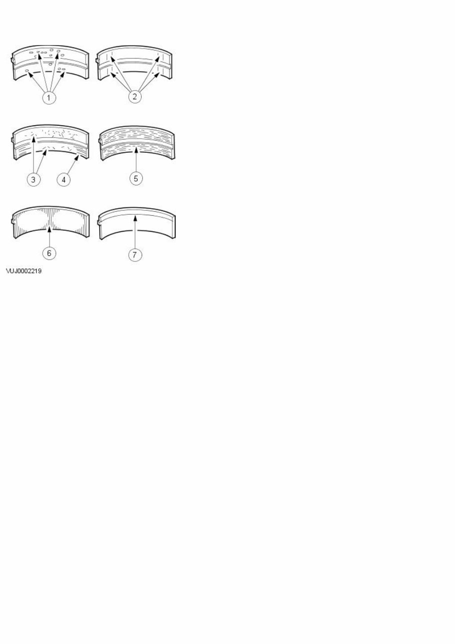
Published: 11-May-2011 Engine System - General Information - Bearing Inspection General Procedures 1. Inspect bearings for the following defects. 1. Cratering - fatigue failure 2. Spot polishing - incorrect seating. 3. Imbedded dirt engine oil. 4. Scratching - dirty engine oil. 5. Base exposed - poor lubrication. 6. Both edges worn - journal damaged. 7. One edge worn - journal tapered or bearing not seated.
This 2013 Jaguar XF (X250) Service & Repair Manual provides factory procedures and specifications for servicing the full range of gasoline and diesel engines available in the 2013 XF lineup. Whether you’re working on a turbocharged 4-cylinder base model or a 4.2L supercharged V8, this manual offers the same depth of documentation used by authorized Jaguar technicians.
From electrical system diagnostics to transmission and suspension service, each chapter includes step-by-step instructions, torque specs, exploded diagrams, and safety notes. It's a must-have resource for independent shops, restoration specialists, or XF owners who prefer to handle maintenance and repairs on their own terms.
Content Overview:
General vehicle information and service guidelines
Detailed chassis repair and suspension system coverage
Complete powertrain diagnostics, engine, and transmission procedures
Electrical system troubleshooting and full wiring diagrams
Full exterior and interior body repair, including paint and trim specifications
Whether you're chasing down an electrical fault, refreshing the suspension, or rebuilding the engine, this manual ensures you have the accurate and detailed guidance needed to do the job right.
Printable: Yes Language: English Compatibility: Pretty much any electronic device Requirements: Adobe Reader (free)