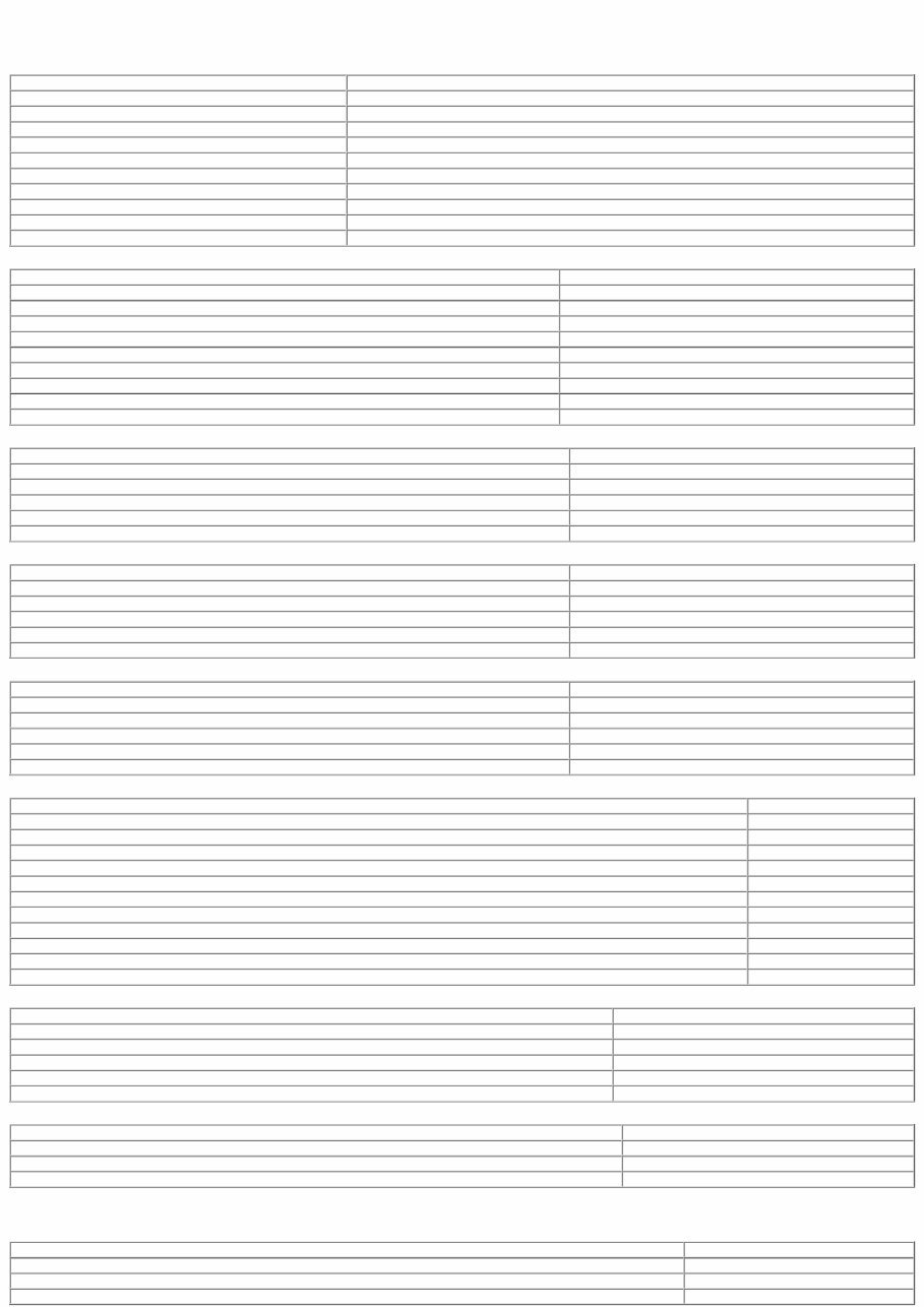
Published: 11-May-2011 Engine System - General Information - General specifications 2.0 litre diesel. Item Specification Code FMBA/FMBB Firing order 1-3-4-2 Cylinder bore diameter 86 mm Stroke 86 mm Displacement 1998 cc Compression ratio 19:1 Engine weight 195 kg (excluding front end accessory drive) Power output at 3800 rpm 96 kW (130 PS) Torque at 1800 rpm 325 Nm Idle speed 900 rpm General specifications 2.2 litre diesel. Item Specification Code QJBA Firing order 1-3-4-2 Cylinder bore diameter 86 mm Stroke 94.6 mm Displacement 2198 cc Compression ratio 19:1 Power output at 3800 rpm 114 kW (155 PS) Torque at 1800 rpm 360 Nm Idle speed 800 rpm General specifications 2.0 litre. Item Specification Displacement in liters 2.099 Number of cylinders 6 Bore and stroke (mm) 81.6 x 66.84 Firing order 1,4,2,5,3,6 Compression ratio 10.75:1 General specifications 2.5 litre. Item Specification Displacement in liters 2.495 Number of cylinders 6 Bore and stroke (mm) 81.6 x 79.5 Firing order 1,4,2,5,3,6 Compression ratio 10.3:1 General specifications 3.0 litre. Item Specification Displacement in liters 2.967 Number of cylinders 6 Bore and stroke (mm) 89.0 x 79.5 Firing order 1,4,2,5,3,6 Compression ratio 10.5:1 Cylinder Block Dimensions 2.0 litre and 2.2 litre diesel. Description mm Cylinder bore diameter – Class 1 86·000 - 86·010 Cylinder bore diameter – Class 2 86·010 - 86·020 Cylinder bore diameter – Class 3 86·020 - 86·030 Main bearing shells 1 to 4 – inside diameter (bearings installed) 65·003 - 65·030 Main bearing shells 5 – inside diameter (bearings installed) 70·004 - 70·033 Main bearings 1 to 4 – radial clearance 0·033 - 0·080 Main bearing 5 – radial clearance 0·034 - 0·083 Main bearings 1 to 4 – parent bore diameter – vertical measurement 64·504 - 64·520 Main bearing 5 – parent bore diameter – vertical measurement 74·504 - 74·520 Main bearings 1 to 4 – parent bore diameter – horizontal measurement 69·502 - 69·525 Main bearing 5 – parent bore diameter – horizontal measurement 74·502 - 74·525 Piston Dimensions 2.0 litre and 2.2 litre diesel. Description mm Piston cooling code 6 Piston diameter – Class A 85·94 - 85·95 Piston diameter – Class B 85·95 - 85·96 Piston diameter – Class C 85·96 - 85·97 Piston clearance in cylinder 0·05 - 0·07 Piston ring gap – piston ring installed 2.0 litre and 2.2 litre diesel. Description mm Upper compression ring 0·25 - 0·50 Lower compression ring 0·50 - 0·75 Oil scraper ring 0·25 - 0·40 Piston ring gap position: Distribute the piston ring gaps evenly around the circumference of the piston. This also applies to the oil control scraper ring elements. Position the ring gaps offset at 120 degrees to one another. Piston Pin Dimensions 2.0 litre and 2.2 litre diesel. Description mm Piston pin - length 66·700 Piston pin – diameter 30·000 Piston pin - clearance in piston pin bore 0·002 - 0·012
Crankshaft Dimensions 2.0 litre and 2.2 litre diesel. Description mm Main bearing journal – diameter 69·950 - 69·970 Main bearing journal – end float 0·090 - 0·305 Big-end bearing journal – diameter 52·980 - 53·000 Main bearing journals 1 to 4 – diameter 64·950 - 64·970 Connecting Rod Dimensions 2.0 litre and 2.2 litre diesel. Description mm Big-end bore – diameter 55·996 - 56·016 Small-end bore – diameter 30·010 - 30·018 Bid-end bearing shell – inside diameter (bearings installed) - Vehicle with 2.0L diesel engine 56·004 - 56·032 Bid-end bearing shell – inside diameter (bearings installed) - Vehicle with 2.2L diesel engine 53·034 - 53·080 Big-end bearing – radial clearance 0·034 - 0·100 Big-end bearing – end float 0·100 - 0·320 Camshaft Dimensions 2.0 litre and 2.2 litre diesel. Description mm Camshaft bearing journal – diameter 26·450 Camshaft bearing clearance – radial measurement 0·065 Camshaft – end float 0·125 Valves 2.0 litre and 2.2 litre diesel. Description mm Valve stem to valve guide clearance – intake valve 0·045 Valve stem to valve guide clearance – exhaust valve 0·055 Cylinder Head 2.0 litre and 2.2 litre diesel. Description mm Thickness of cylinder head gasket with piston protrusion of 0·430 - 0·520 mm 1·10 (1 hole/tooth) Thickness of cylinder head gasket with piston protrusion of 0·521 - 0·570 mm 1·15 (2 holes/teeth) Thickness of cylinder head gasket with piston protrusion of 0·571 - 0·620 mm 1·20 (3 holes/teeth) Maximum longitudinal/diagonal distortion of cylinder head surface 0·100 Peak to valley height of mating surface 0·020 Cylinder Head and Valve Train 2.0 litre. Item Specification Valve guide inner diameter (mm) 5.514 - 5.544 Intake valve effective length (mm) 91.13 - 90.93 Exhaust valve effective length (mm) 89.88 - 89.68 Valve stem to guide clearance intake - diameter (mm) 0.067 - 0.022 Valve stem to guide clearance exhaust - diameter (mm) 0.080 - 0.035 Valve head diameter intake (mm) 30.15 - 29.85 Valve head diameter exhaust (mm) 26.15 - 25.85 Intake valve face angle degree 45.75° Exhaust valve face angle degree 45.25° Valve stem diameter intake (mm) 5.492 - 5.477 Valve stem diameter exhaust (mm) 5.479 - 5.464 Valve spring free length (mm) 44.2 Valve spring installed height (mm) 33.41 Camshaft lobe lift intake (mm) 8.876 Camshaft lobe lift exhaust (mm) 8.876 Camshaft end play (mm) 0.150 - 0.070 Camshaft journal to cylinder head bearing surface clearance diameter (mm) 0.076 - 0.025 Camshaft journal diameter standard runout limit (mm) 0.040 Camshaft journal diameter standard out of round (mm) 0.013 Cylinder Head and Valve Train 2.5 litre. Item Specification Valve guide inner diameter (mm) 5.514 - 5.544 Intake valve effective length (mm) 91.13 - 90.93 Exhaust valve effective length (mm) 89.88 - 89.68 Valve stem to guide clearance intake - diameter (mm) 0.067 - 0.022 Valve stem to guide clearance exhaust - diameter (mm) 0.080 - 0.035 Valve head diameter intake (mm) 30.15 - 29.85 Valve head diameter exhaust (mm) 26.15 - 25.85 Intake valve face angle degree 45.75° Exhaust valve face angle degree 45.25° Valve stem diameter intake (mm) 5.492 - 5.477 Valve stem diameter exhaust (mm) 5.479 - 5.464 Valve spring free length (mm) 44.2 Valve spring installed height (mm) 33.41 Camshaft lobe lift intake (mm) 9.367 Camshaft lobe lift exhaust (mm) 9.461 Camshaft end play (mm) 0.150 - 0.070 Camshaft journal to cylinder head bearing surface clearance diameter (mm) 0.076 - 0.025 Camshaft journal diameter standard runout limit (mm) 0.040 Camshaft journal diameter standard out of round (mm) 0.013 Cylinder Head and Valve Train 3.0 litre. Item Specification Valve guide inner diameter (mm) 5.514 - 5.544 Intake valve effective length (mm) 91.13 - 90.93 Exhaust valve effective length (mm) 89.88 - 89.68 Valve stem to guide clearance intake - diameter (mm) 0.067 - 0.022 Valve stem to guide clearance exhaust - diameter (mm) 0.080 - 0.035 Valve head diameter intake (mm) 35.15 - 34.85
Item Specification Valve head diameter exhaust (mm) 30.15 - 29.85 Intake valve face angle degree 45.75° Exhaust valve face angle degree 45.25° Valve stem diameter intake (mm) 5.492 - 5.477 Valve stem diameter exhaust (mm) 5.479 - 5.464 Valve spring free length (mm) 44.2 Valve spring installed height (mm) 33.41 Camshaft lobe lift intake (mm) 9.367 Camshaft lobe lift exhaust (mm) 9.461 Camshaft end play (mm) 0.150 - 0.070 Camshaft journal to cylinder head bearing surface clearance diameter (mm) 0.076 - 0.025 Camshaft journal diameter standard runout limit (mm) 0.040 Camshaft journal diameter standard out of round (mm) 0.013 Lubrication system 2.0 litre and 2.2 litre diesel. Item Liters Oil capacity with filter 6.7 Lubrication system 2.0, 2.5 and 3.0 litre. Item Liters Oil capacity with filter 6.5
Published: 11-May-2011 Engine System - General Information - Engine Description and Operation 2.0L, 2.5L and 3.0L Engines The 2.0L, 2.5L and 3.0L engines consists of: A six cylinder 60 degree 'V' configuration liquid cooled aluminium cylinder block with dry cast iron liners. Aluminium pistons with cut-outs in the piston crown to clear the valve heads for any available combination of camshaft profile and valve phasing. Two aluminium cylinder heads with square squish chambers. Two cast iron overhead camshafts per bank. Four valves per cylinder. Mechanical tappets and top mounted steel shims. Continuous variable camshaft timing (VCT) of the inlet camshafts. Two silent timing chains with one hydraulic tensioner per chain. Magnesium alloy camshaft covers with rubber seals. A variable intake system containing two electrically controlled intake manifold tuning valves. Plastic lower intake manifold with integral fuel rail and injectors. Aluminium timing cover which accommodates the crankshaft front oil seal. An oil pump mounted around the crankshaft. An aluminium bed plate. An aluminium oil pan. A steel crankshaft (2.5L and 3.0L engines only). A cast iron crankshaft (2.0L engines only). Fracture-split connecting rods in sintered-forged steel. A single, six ribbed vee belt drives the front end accessories. A water pump belt pulley mounted directly to the exhaust camshaft of the left-hand cylinder head. A single, three ribbed vee belt which drives the water pump. A water pump mounted on the rear of the left-hand cylinder head. An advanced engine management system incorporating electronic throttle control. The unit meets the requirements of the CARB OBDII USA legislation. CAUTION: The use of supplementary oil or fuel additives is not approved unless specified by Jaguar cars in the form of a service communication or directive. The engine code and serial number is located on the left-hand side of the bed plate near the oil cooler assembly. 2.0L and 2.2L common rail diesel engine The 2.0L and 2.2L common rail diesel engine consists of: a four cylinder cast iron cylinder block a aluminium cylinder head a separate camshaft carrier a forged steel crankshaft with eight counterweights lightweight aluminium alloy pistons fracture split connecting rods a multi link drive chain which drives the camshafts and the high pressure pump a single link chain which drives a gear-type oil pump hydraulically operated timing chain tensioner fabricated camshafts with sintered lobes roller rocker valve actuation two exhaust valves and two inlet valves per cylinder a plastic composite camshaft cover a pressed steel timing cover which must be aligned using the special tool a engine oil cooler is mounted to the left hand side of the engine a water pump is mounted to the left hand rear of the engine and driven via the rear of the power steering pump a power steering pump is mounted to the left hand rear of the engine and driven by the rear of the intake camshaft via a multi-vee belt a variable vain turbocharger.
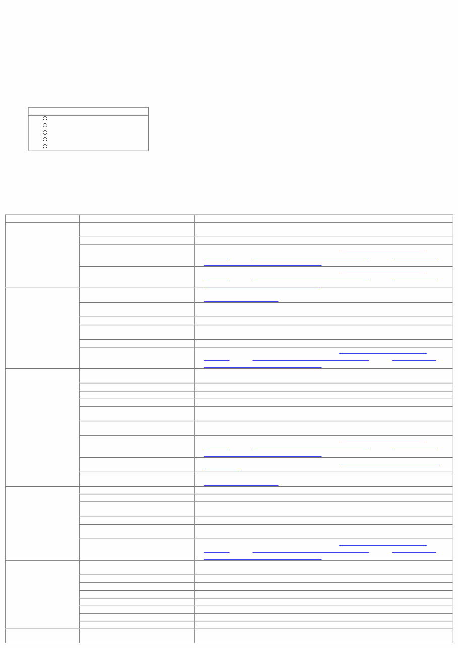
* * * * * * * * * * * * * * * * * * * * * * * * * * * * * * * * * * * * * * * * * * * * * * * * * * * * * * * * * * * * * * * * * * * * Published: 11-May-2011 Engine System - General Information - Engine Diagnosis and Testing Inspection and Verification Since diagnosis and testing actually begins when repairs are taken on, the following procedure is recommended. 1. Verify the customer concern by operating the system. 1. 2. Visually inspect for obvious signs of mechanical damage or electrical damage. If the concern cannot be reproduced, carry out a road test and/or visual check with the aid of the following table. Visual Inspection Chart Mechanical Coolant leaks Oil leaks Leaks in the fuel system Visibly damaged or worn parts Loose or missing nuts or bolts 2. 3. If an obvious cause for an observed or reported concern is found, correct the cause (if possible) before proceeding to the next step. 3. 4. If the concern is not visually evident, verify the symptom and refer to the Symptom Chart. 4. Symptom Chart Symptom Chart Symptom Possible Sources Action Difficult to start during hot or cold start Piston ring(s) worn, damaged, sticking or worn piston/cylinder. INSTALL a new engine. Head gasket damaged. INSPECT the head gasket. Fuel system damaged or inoperative. For additional information, refer to Section 303-04A Fuel Charging and ControlsSection 303-04B Fuel Charging and ControlsSection 303-04C Fuel Charging and Controls - Turbocharger. Ignition system inoperative. For additional information, refer to Section 303-04A Fuel Charging and ControlsSection 303-04B Fuel Charging and ControlsSection 303-04C Fuel Charging and Controls - Turbocharger. Poor Idling Restricted exhaust system. INSPECT the exhaust system. For additional information, refer to Section 309-00 Exhaust System. Vacuum leak. CARRY out the Intake Manifold Vacuum Test in this section. REPAIR and INSTALL new components as necessary. Burned valve(s). INSPECT the valve(s). Incorrect valve to valve seat contact. INSPECT the valve and valve seat. Head gasket damaged. INSPECT the head gasket. Fuel system damaged or inoperative. For additional information, refer to Section 303-04A Fuel Charging and ControlsSection 303-04B Fuel Charging and ControlsSection 303-04C Fuel Charging and Controls - Turbocharger. Insufficient power Compression leakage from valve seat. INSPECT the valve or valve seat. Valve sticking. INSPECT valve stem to valve guide clearance or carbon accumulation. Valve spring weak or broken. INSPECT the valve spring. Head gasket damaged. INSPECT the head gasket. Cylinder head cracked or distorted. INSPECT the cylinder head. Piston ring(s) worn, damaged or sticking. INSTALL a new engine. Fuel system damaged or inoperative. For additional information, refer to Section 303-04A Fuel Charging and ControlsSection 303-04B Fuel Charging and ControlsSection 303-04C Fuel Charging and Controls - Turbocharger. Brakes dragging. For additional information, refer to Section 206-00 Brake System - General Information. Restricted exhaust system. INSPECT the exhaust system. For additional information, refer to Section 309-00 Exhaust System. Excessive or insufficient compression. Valve(s) burnt or sticking. INSPECT the valve(s). Valve spring(s) weak or broken. INSPECT the valve spring(s). Piston ring(s) worn, damaged, sticking or worn piston/cylinder. INSTALL a new engine. Head gasket damaged. INSPECT the head gasket. Carbon accumulation in combustion chamber. ELIMINATE carbon build up. Fuel system damaged or inoperative. For additional information, refer to Section 303-04A Fuel Charging and ControlsSection 303-04B Fuel Charging and ControlsSection 303-04C Fuel Charging and Controls - Turbocharger. Excessive oil consumption Piston ring(s) worn, damaged, sticking or worn piston/cylinder. INSTALL a new engine. Valve stem seal worn or missing. INSPECT the valve or valve stem seal. Oil leakage. REPAIR oil leakage. Valve stem or valve guide worn. INSPECT the valve stem or valve guide. Incorrect oil viscosity. DRAIN and FILL with new oil. Diluted oil. CHECK oil dilution. DRAIN and FILL as necessary. Crankcase overfilled. CHECK and adjust the oil level. Incorrect oil pressure. CHECK the oil pressure. REPAIR as necessary. Engine noise Excessive crankshaft main bearing clearance. INSTALL a new engine.
You're Reading a Preview
What's Included?
Lifetime Access
Fast Download Speeds
Offline Viewing
Access Contents & Bookmarks
Full Search Facility
Print one or all pages of your manual
$31.99
2008-2009 Jaguar Xf Xfr X250 Service & Repair Manual
This is the complete official full factory service repair manual for the Jaguar XF XFR X250 2008 2009. It is your number one source for repair and service information, providing step-by-step instructions based on the complete disassembly of the machine. This manual is useful for both professional mechanics and DIY enthusiasts. It covers general maintenance, troubleshooting, engine service/repair, transmission service/repair, brake system, wiring diagram, electrical system, suspension, periodic lubrication, steering, cooling system, fuel injection, fuel system, emission system, heater/air conditioning, engine control system, chassis/body, restraint system, interior, differential/drive, and axle, as well as much more information.
The manual comes in .PDF format and can work under all PC-based Windows operating systems and Mac. It is printable and does not have any restrictions. The language used is English, and it requires Adobe Reader for access. This is a full professional quality in-depth service and repair manual for Jaguar XF XFR X250 2008 2009.
Get your Jaguar XF XFR X250 2008 2009 service manual now and have access to detailed substeps, notes, cautions, warnings, numbered instructions, bold figure numbers, detailed illustrations, drawings, photos, and an enlarged inset to help you identify and examine parts in detail. The manual also makes it easy to diagnose and repair problems with your machine's electrical system, with troubleshooting and electrical service procedures combined with detailed wiring diagrams for ease of use.