

2007 Jaguar X-Type Service & Repair Manual Software
What's Included?
Fast Download Speeds
Offline Viewing
Access Contents & Bookmarks
Full Search Facility
Print one or all pages of your manual
BY APPOINTMENT TO
HER MAJESTY QUEEN ELIZABETH II
MANUFACTURERS OF DAIMLER AND JAGUAR CARS
JAGUAR CARS LIMITED COVENTRY
BY APPOINTMENT TO
HER MAJESTY QUEEN ELIZABETH
THE QUEEN MOTHER
MANUFACTURERS OF DAIMLER AND JAGUAR CARS
JAGUAR CARS LIMITED COVENTRY
BY APPOINTMENT TO
HIS ROYAL HIGHNESS THE PRINCE OF WALES
MANUFACTURERS OF DAIMLER AND JAGUAR CARS
JAGUAR CARS LIMITED COVENTRY
Jaguar Cars Limited
2004.25 / 2004.5 Electrical Guide
Sedan and Estate (Wagon)
2.0 L, 2.5 L and 3.0 L Gasoline; 2.0 L Diesel
Model Years: Sedan 2004.25, Estate (Wagon) 2004.5
Published by Technical Support and Communications
Publication Part Number – JJM 10 38 20 / 42


1
DATE OF ISSUE: August 2003
X-TYPE 2004.25 / 2004.5 Table of Contents
Table of Contents ................................................................................................................................ 1
Table of Contents: Figures ................................................................................................................... 2–3
Abbreviations and Acronyms ............................................................................................................... 4
Introduction ........................................................................................................................................ 5
Component Index ............................................................................................................................... 6 – 11
User Instructions ............................................................................................................................... 12 – 13
Symbols and Codes ........................................................................................................................... 14 – 17
Network Configuration ...................................................................................................................... 18
Relay and Fuse Location .................................................................................................................... 19 – 20
Fuse Box Connectors ......................................................................................................................... 21
Major Harnesses and Fuse Box Location ............................................................................................. 22 – 23
Harness In-Line Connector Location .................................................................................................. 24 – 26
Ground Point Location ...................................................................................................................... 27
Control Module Location ................................................................................................................... 28 – 29
Control Module Pin Identification ...................................................................................................... 30 – 37
Electrical Guide Figures and Data ............................................................................ follows after page 37
(pages are numbered by Figure number)

2
DATE OF ISSUE: August 2003
X-TYPE 2004.25 / 2004.5 Table of Contents: Figures
FIGURES
Fig. Description Variant
01 Power Distribution
01.1 ............ Main Power Distribution ............................................................................ All Vehicles
01.2 ............ Battery Power Distribution: Part 1 .............................................................. All Vehicles
01.3 ............ Battery Power Distribution: Part 2 .............................................................. All Vehicles
01.4 ............ Ignition Switched Power Distribution: I (Accessory) ..................................... All Vehicles
01.5 ............ Ignition Switched Power Distribution: II (Run) – Part 1 ................................ All Vehicles
01.6 ............ Ignition Switched Power Distribution: II (Run) – Part 2 ................................ All Vehicles
01.7 ............ Ignition Switched Power Distribution: Battery Saver .................................... All Vehicles
01.8 ............ EMS Switched Power Distribution: Gasoline Engines ................................... Gasoline Engine Vehicles
01.9 ............ EMS Switched Power Distribution: Diesel Engine ........................................ Diesel Engine Vehicles
02 Battery; Starter; Generator
02.1 ............ Battery; Starter; Generator: 2.5 L & 3.0 L .................................................... 2.5 L & 3.0 L Vehicles
02.2 ............ Battery; Starter; Generator: 2.0 L ................................................................ 2.0 L Gasoline Engine Vehicles
02.3 ............ Battery; Starter; Generator: 2.0 L D ............................................................ 2.0 L Diesel Engine Vehicles
03 Engine Management
03.1 ............ Engine Management: 2.5 L & 3.0 L – Part 1 ................................................. 2.5 L & 3.0 L Vehicles
03.2 ............ Engine Management: 2.5 L & 3.0 L – Part 2 ................................................. 2.5 L & 3.0 L Vehicles
03.3 ............ Engine Management: 2.0 L – Part 1 ............................................................ 2.0 L Gasoline Engine Vehicles
03.4 ............ Engine Management: 2.0 L – Part 2 ............................................................ 2.0 L Gasoline Engine Vehicles
03.5 ............ Engine Management: 2.0 L D – Part 1 ......................................................... 2.0 L Diesel Engine Vehicles
03.6 ............ Engine Management: 2.0 L D – Part 2 ......................................................... 2.0 L Diesel Engine Vehicles
04 Transmission
04.1 ............ Automatic Transmission: 16-Bit TCM .......................................................... 16-Bit TCM Vehicles
04.2 ............ Automatic Transmission: 32-Bit TCM .......................................................... 32-Bit TCM Vehicles
05 Braking
05.1 ............ Anti-Lock Braking ...................................................................................... ABS Vehicles
05.2 ............ Anti-Lock Braking / Traction Control ........................................................... ABS / TC Vehicles
05.3 ............ Dynamic Stability Control .......................................................................... DSC Vehicles
06 Climate Control
06.1 ............ Manual Climate Control ............................................................................. Manual Climate Control Vehicles
06.2 ............ Automatic Climate Control ......................................................................... Automatic Climate Control Vehicles
06.3 ............ Glass Heaters ............................................................................................ All Vehicles
07 Instrumentation
07.1 ............ Instrument Cluster ..................................................................................... All Vehicles
07.2 ............ Audible Warnings ...................................................................................... All Vehicles
08 Exterior Lighting
08.1 ............ Exterior Lighting: Front – Auto Headlamps ................................................. Auto Headlamp Vehicles
08.2 ............ Exterior Lighting: Front – Non Autolamps ................................................... Non Autolamp Vehicles;
Exterior Lighting: Front – Daytime Running Lamps ...................................... Daytime Running Lamp Vehicles
08.3 ............ Exterior Lighting: Rear – Sedan ................................................................... Sedan Vehicles
08.4 ............ Exterior Lighting: Rear – Estate (Wagon) ...................................................... Estate (Wagon) Vehicles
08.5 ............ Exterior Lighting: Rear – Sedan European Trailer Towing ............................. Euro. Sedan Trailer Towing Vehicles
08.6 ............ Exterior Lighting: Rear – Sedan U.K. Trailer Towing ..................................... U.K. Sedan Trailer Towing Vehicles
08.7 ............ Exterior Lighting: Rear – Sedan NAS Trailer Towing ..................................... NAS Sedan Trailer Towing Vehicles
08.8 ............ Exterior Lighting: Rear – Estate (Wagon) European Trailer Towing ................ Euro. Estate (Wagon) Trailer Towing Vehicles
08.9 ............ Exterior Lighting: Rear – Estate (Wagon) U.K. Trailer Towing ....................... U.K. Estate (Wagon) Trailer Towing Vehicles
08.10 .......... Headlamp Leveling (H/L) ............................................................................ H/L & HID Headlamp Vehicles
09 Interior Lighting
09.1 ............ Interior Lighting ......................................................................................... All Vehicles
09.2 ............ Dimmer-Controlled Lighting ....................................................................... All Vehicles

3
DATE OF ISSUE: August 2003
X-TYPE 2004.25 / 2004.5 Table of Contents: Figures
FIGURES
Fig. Description Variant
10 Door Mirrors
10.1 ............ Door Mirrors: Movement; Fold-Back – Non Memory .................................. Non Memory Vehicles
10.2 ............ Door Mirrors: Movement; Fold-Back – Memory .......................................... Memory Vehicles
11 Seat Systems
11.1 ............ Powered Seat: Driver – Memory ................................................................. Memory Vehicles
11.2 ............ Powered Seat: Passenger – Memory ........................................................... Memory Vehicles
11.3 ............ Powered Seats: 8-Way Movement .............................................................. 8-Way Powered Seat Vehicles
11.4 ............ Powered Seats: 4-Way Movement .............................................................. 4-Way Powered Seat Vehicles
11.5 ............ Powered Seats: 2-Way Movement .............................................................. 2-Way Powered Seat Vehicles
11.6 ............ Seat Heaters: Memory ............................................................................... Memory Vehicles
11.7 ............ Seat Heaters: Non Memory ........................................................................ Heated Seat Vehicles
12 Door Locking; Security
12.1 ............ Central Door Locking: Sedan – Double Locking ........................................... Double Locking Sedan Vehicles
12.2 ............ Central Door Locking: Sedan – Non Double Locking ................................... Non Double Locking Sedan Vehicles
12.3 ............ Central Door Locking: Estate (Wagon) ......................................................... Estate (Wagon) Vehicles
12.4 ............ Security: Sedan .......................................................................................... Sedan Vehicles
12.5 ............ Security: Estate (Wagon) ............................................................................. Estate (Wagon) Vehicles
13 Wash / Wipe
13.1 ............ Wash / Wipe: Front ................................................................................... Non Rain Sensing Vehicles
13.2 ............ Wash / Wipe: Front with Rain Sensing ........................................................ Rain Sensing Vehicles
13.3 ............ Wash / Wipe: Rear ..................................................................................... Estate (Wagon) Vehicles
14 Powered Windows; Sliding Roof
14.1 ............ Powered Windows .................................................................................... All Vehicles
14.2 ............ Sliding Roof ............................................................................................... Sliding Roof Vehicles
15 In-Car Entertainment
15.1 ............ In-Car Entertainment – Standard ................................................................ Standard ICE Vehicles
15.2 ............ In-Car Entertainment – Premium ................................................................ Premium ICE Vehicles
16 Telematics
16.1 ............ Telephone: ROW ....................................................................................... ROW Vehicles
16.2 ............ Telephone: NAS ........................................................................................ NAS Vehicles
16.3 ............ Telephone with Voice Control: ROW .......................................................... ROW Voice Vehicles
16.4 ............ Telephone with Voice Control: NAS ........................................................... NAS Voice Vehicles
16.5 ............ Navigation System ..................................................................................... NAV Vehicles (except Japan)
16.6 ............ Navigation System: Japan ........................................................................... Japan Vehicles
17 Occupant Protection
17.1 ............ Advanced Restraint System: Front Wheel Drive .......................................... Front Wheel Drive Vehicles
17.2 ............ Advanced Restraint System: All Wheel Drive .............................................. All Wheel Drive Vehicles
18 Driver Assist
18.1 ............ Parking Aid ................................................................................................ Parking Aid Vehicles
19 Ancillaries
19.1 ............ Ancillaries: Horn; Cigar Lighter; Accessory Connectors; ............................... All Vehicles
Garage Door Opener; Electrochromic Rear View Mirror
20 Vehicle Multiplex Systems
20.1 ............ Controller Area Network: LHD ................................................................... LHD Vehicles
20.2 ............ Controller Area Network: RHD .................................................................. RHD Vehicles
20.3 ............ Standard Corporate Protocol Network; Serial Data Link .............................. All Vehicles
20.4 ............ D2B Network ............................................................................................ All Vehicles

4
DATE OF ISSUE: August 2003
X-TYPE 2004.25 / 2004.5 Abbreviations and Acronyms
The following abbreviations and acronyms are used throughout this Electrical Guide:
A/C Air Conditioning
APP SENSOR Accelerator Pedal Position Sensor
APP1 Accelerator Pedal Position Sensor Element 1
APP2 Accelerator Pedal Position Sensor Element 2
APP3 Accelerator Pedal Position Sensor Element 3
AWD All Wheel Drive
B+ Battery Voltage
BANK 1 RH Cylinder Bank (Cylinders 1, 3, 5)
BANK 2 LH Cylinder Bank (Cylinders 2, 4, 6)
CAN Controller Area Network
CHT SENSOR Cylinder Head Temperature Sensor
CKP SENSOR Crankshaft Position Sensor
CMP SENSOR / 1 Camshaft Position Sensor / RH Bank
CMP SENSOR / 2 Camshaft Position Sensor / LH Bank
D2B D2B Network
ECT SENSOR Engine Coolant Temperature Sensor
EFT SENSOR Engine Fuel Temperature Sensor
EGR VALVE Exhaust Gas Recirculation Valve
EGT SENSOR Exhaust Gas Temperature Sensor
EMS Engine Management System
EOT SENSOR Engine Oil Temperature Sensor
EST / WAG Estate / Wagon Vehicles
EVAP CANISTER CLOSE VALVE Evaporative Emission Canister Close Valve
EVAP CANISTER PURGE VALVE Evaporative Emission Canister Purge Valve
FTP SENSOR Fuel Tank Pressure Sensor
FWD Front Wheel Drive
GPS Global Positioning System
HID High Intensity Discharge
HO2 SENSOR 1 / 1 Heated Oxygen Sensor – RH Bank / Upstream
HO2 SENSOR 1 / 2 Heated Oxygen Sensor – RH Bank / Downstream
HO2 SENSOR 2 / 1 Heated Oxygen Sensor – LH Bank / Upstream
HO2 SENSOR 2 / 2 Heated Oxygen Sensor – LH Bank / Downstream
IAT SENSOR Intake Air Temperature Sensor
ICE In-Car Entertainment System
IMT SOLENOID VALVE / 1 Intake Manifold Tuning Valve / Bottom
IMT SOLENOID VALVE / 2 Intake Manifold Tuning Valve / Top
IP SENSOR Injection Pressure Sensor
KS Knock Sensor
LH Left Hand
LHD Left Hand Drive
MAF SENSOR Mass Air Flow Sensor
MAP SENSOR Manifold Absolute Pressure Sensor
N/A Normally Aspirated
NAS North American Specification
PATS Passive Anti-Theft System
PWM Pulse Width Modulated
RH Right Hand
RHD Right Hand Drive
ROW Rest of World
SCP Standard Corporate Protocol Network
SEDAN Sedan Vehicles
T-MAP SENSOR Temperature Manifold Absolute Pressure Sensor
TP SENSOR Throttle Position Sensor
TP1 Throttle Position Sensor Element 1
TP2 Throttle Position Sensor Element 2
TURN Turn Signal
TV Television
V6 V6 Engine
VVT SOLENOID VALVE / 1 Variable Valve Timing Valve / Bank 1
VVT SOLENOID VALVE / 2 Variable Valve Timing Valve / Bank 2
+ve Positive
–ve Negative
2.0 L D 2.0 L Diesel Vehicles
2.0 L 2.0 L V6 Vehicles
2.5 L, 3.0 L 2.5 L and 3.0 L V6 Vehicles
5
DATE OF ISSUE: August 2003
X-TYPE 2004.25 / 2004.5 Introduction
Electrical Guide Format
This Electrical Guide is made up of two major sections. The first section, at the front of the book, provides general information for and about
the use of the book, and information and illustrations to aid in the understanding of the Jaguar X-TYPE electrical / electronic systems, as well
as the location and identification of components.
The second section includes the Figures, which are the basis of the book. Each Figure is identified by a Figure Number (i.e. Fig. 01.1) and
Title, and is accompanied by a page of data containing information specific to that Figure.
It is recommended that the user read through the front section of the book to develop a familiarity with the layout of the book and with the
system of symbols and abbreviations used. The Table of Contents should help to guide the user.
Vehicle Identification Numbers (VIN)
VIN ranges are presented throughout the book in the following manner:
➞
VIN 123456 indicates “up to VIN 123456”; VIN 123456
➞
indicates “from VIN 123456 on”.
Jaguar 2004.25 / 2004.5 Model Year X-TYPE Electrical System Architecture
Power Supplies
The Jaguar X-TYPE electrical system is a supply-side switched system. The ignition switch directly carries much of the ignition switched power
supply load. Power supply is provided via three methods: direct battery power supply, ignition switched power supply, and “Battery Saver
Power Supply”. The “Battery Saver Power Supply” circuit is controlled via the GEM (General Electronic Module). Refer to Figure 01.7 for
circuit activation details.
Fuse Boxes
The electrical harness incorporates two serviceable power distribution fuse boxes: the Power Distribution Fuse Box located in the engine
compartment and the Passenger Junction Fuse Box located in the left-hand ‘A’ Post. All fuses and relays (except the trailer towing accessory
kit and two Diesel vehicle relays) are located in the two fuse boxes.
Vehicle Networks
The X-TYPE employs three different networks: a CAN (Controller Area Network) for high-speed power train communications, an SCP
(Standard Corporate Protocol) network for slower speed body systems communications, and a D2B (Optical) Network for very high-speed
“real-time” audio data transfer. The D2B Network is a fiber optic network with a gateway to the remaining vehicle networks via the Audio
Unit. Technician access to the three networks and the Serial Data Link is via the Data Link Connector.
Ground Studs
Circuit ground connections are made at body studs located throughout the vehicle. There are no separate power and logic grounding systems;
however, there are a certain number of components that use unique ground points.
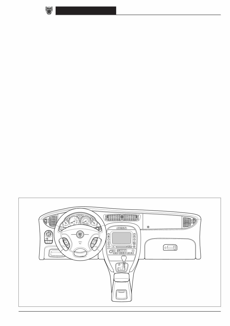
X-TYPE INSTRUMENT PANEL

6
DATE OF ISSUE: August 2003
X-TYPE 2004.25 / 2004.5 Component Index
Accessory Connector – Rear ............................................ Fig. 08.5
...................................................................................... Fig. 08.6
...................................................................................... Fig. 08.7
...................................................................................... Fig. 08.8
...................................................................................... Fig. 08.9
...................................................................................... Fig. 19.1
Accessory Connector – Trailer Towing ............................. Fig. 08.7
...................................................................................... Fig. 08.5
...................................................................................... Fig. 08.6
...................................................................................... Fig. 08.8
...................................................................................... Fig. 08.9
Accessory Connector – Cabin .......................................... Fig. 19.1
Accessory Relay .............................................................. Fig. 01.4
Air Conditioning Blower Relay ......................................... Fig. 06.1
...................................................................................... Fig. 06.2
Air Conditioning Compressor Clutch Relay ...................... Fig. 03.2
...................................................................................... Fig. 03.4
...................................................................................... Fig. 03.6
Air Conditioning Compressor Clutch ............................... Fig. 03.2
...................................................................................... Fig. 03.4
...................................................................................... Fig. 03.6
Air Conditioning Pressure Sensor .................................... Fig. 03.2
...................................................................................... Fig. 03.4
...................................................................................... Fig. 03.6
Air Temperature Blend Actuator ...................................... Fig. 06.1
...................................................................................... Fig. 06.2
AM /FM Antenna – Estate (Wagon) .................................. Fig. 15.1
...................................................................................... Fig. 15.2
Ambient Temperature Sensor – 2.0 L D ........................... Fig. 03.5
Ambient Temperature Sensor .......................................... Fig. 06.2
Antenna Module – Sedan ................................................ Fig. 15.1
...................................................................................... Fig. 15.2
Anti-Lock Braking / Traction Control Module ................... Fig. 05.2
...................................................................................... Fig. 20.1
...................................................................................... Fig. 20.2
Anti-Lock Braking System Module ................................... Fig. 05.1
...................................................................................... Fig. 20.1
...................................................................................... Fig. 20.2
APP Sensor – 2.0 L D ...................................................... Fig. 03.5
APP Sensor – 2.5 L, 3.0 L ................................................ Fig. 03.1
Audio Control Switches ................................................... Fig. 15.1
...................................................................................... Fig. 15.2
Audio Unit ..................................................................... Fig. 09.2
...................................................................................... Fig. 12.4
...................................................................................... Fig. 12.5
...................................................................................... Fig. 15.1
...................................................................................... Fig. 15.2
...................................................................................... Fig. 16.1
...................................................................................... Fig. 16.2
...................................................................................... Fig. 16.3
...................................................................................... Fig. 16.4
...................................................................................... Fig. 20.3
...................................................................................... Fig. 20.4
Auto Headlamps Sensor .................................................. Fig. 08.1
Automatic Transmission .................................................. Fig. 04.1
...................................................................................... Fig. 04.2
Auxiliary Heater Relays ................................................... Fig. 03.6
Axle Sensors ................................................................... Fig. 08.10
Battery Saver Relay ......................................................... Fig. 01.7
Battery ........................................................................... Fig. 01.1
...................................................................................... Fig. 02.1
...................................................................................... Fig. 02.2
...................................................................................... Fig. 02.3
Blower – Automatic Climate Control ............................... Fig. 06.2
Blower – Manual Climate Control .................................... Fig. 06.1
Blower Series Resistor ..................................................... Fig. 06.1
Brake Cancel Switch ....................................................... Fig. 03.2
...................................................................................... Fig. 03.4
...................................................................................... Fig. 03.6
Brake Fluid Level Switch ................................................. Fig. 07.1
Brake On / Off Switch ..................................................... Fig. 03.1
...................................................................................... Fig. 03.3
...................................................................................... Fig. 03.4
...................................................................................... Fig. 03.5
...................................................................................... Fig. 03.6
...................................................................................... Fig. 05.1
...................................................................................... Fig. 05.2
...................................................................................... Fig. 05.3
...................................................................................... Fig. 08.3
...................................................................................... Fig. 08.4
Brake Pressure Sensor ..................................................... Fig. 05.3
Caravan Connector ......................................................... Fig. 08.6
...................................................................................... Fig. 08.9
CD Autochanger ............................................................. Fig. 15.1
...................................................................................... Fig. 15.2
...................................................................................... Fig. 20.4
Cellular Phone Module ................................................... Fig. 16.1
...................................................................................... Fig. 16.2
...................................................................................... Fig. 16.3
...................................................................................... Fig. 16.4
...................................................................................... Fig. 20.4
CHT Sensor .................................................................... Fig. 03.5
Cigar Lighter ................................................................... Fig. 09.2
...................................................................................... Fig. 19.1
CKP Sensor – 2.0 L D ...................................................... Fig. 03.5
CKP Sensor – 2.0 L, 2.5 L, 3.0 L ....................................... Fig. 03.1
...................................................................................... Fig. 03.3
Climate Control Module – Panel ...................................... Fig. 06.1
...................................................................................... Fig. 06.3
...................................................................................... Fig. 09.2
...................................................................................... Fig. 20.1
...................................................................................... Fig. 20.2
Climate Control Module – Remote .................................. Fig. 06.2
...................................................................................... Fig. 06.3
...................................................................................... Fig. 20.1
...................................................................................... Fig. 20.2
Clutch Cancel Switch ...................................................... Fig. 03.2
...................................................................................... Fig. 03.4
Clutch Pedal Safety Switch .............................................. Fig. 02.1
Clutch Switch – 2.0 L D ................................................... Fig. 03.5
...................................................................................... Fig. 03.6
CMP Sensor – 2.0 L D ..................................................... Fig. 03.5
CMP Sensors – 2.0 L, 2.5 L, 3.0 L ..................................... Fig. 03.1
...................................................................................... Fig. 03.3
Cooling Fans ................................................................... Fig. 03.2
...................................................................................... Fig. 03.4
...................................................................................... Fig. 03.6
Cooling Fan Module ........................................................ Fig. 03.2
...................................................................................... Fig. 03.4
...................................................................................... Fig. 03.6
Curtain Airbag Igniters .................................................... Fig. 17.1
...................................................................................... Fig. 17.2
Customer Power Connector ............................................ Fig. 19.1

7
DATE OF ISSUE: August 2003
X-TYPE 2004.25 / 2004.5 Component Index
Data Link Connector ....................................................... Fig. 20.1
...................................................................................... Fig. 20.2
...................................................................................... Fig. 20.3
Defrost Door Actuator .................................................... Fig. 06.1
...................................................................................... Fig. 06.2
Dip Beam Relay .............................................................. Fig. 08.1
...................................................................................... Fig. 08.2
Discharge Temperature Sensor ........................................ Fig. 06.1
...................................................................................... Fig. 06.2
Door Latch – Driver ........................................................ Fig. 07.2
...................................................................................... Fig. 09.1
...................................................................................... Fig. 11.1
...................................................................................... Fig. 12.1
...................................................................................... Fig. 12.2
...................................................................................... Fig. 12.3
...................................................................................... Fig. 12.4
...................................................................................... Fig. 12.5
...................................................................................... Fig. 14.1
...................................................................................... Fig. 14.2
Door Latch – LH Rear ...................................................... Fig. 09.1
...................................................................................... Fig. 12.1
...................................................................................... Fig. 12.2
...................................................................................... Fig. 12.3
...................................................................................... Fig. 12.4
...................................................................................... Fig. 12.5
Door Latch – Passenger ................................................... Fig. 09.1
...................................................................................... Fig. 12.1
...................................................................................... Fig. 12.2
...................................................................................... Fig. 12.3
...................................................................................... Fig. 12.4
...................................................................................... Fig. 12.5
Door Latch – RH Rear ..................................................... Fig. 09.1
...................................................................................... Fig. 12.1
...................................................................................... Fig. 12.2
...................................................................................... Fig. 12.3
...................................................................................... Fig. 12.4
...................................................................................... Fig. 12.5
Door Mirrors .................................................................. Fig. 06.3
...................................................................................... Fig. 10.2
...................................................................................... Fig. 10.3
Door Switch Pack – Driver .............................................. Fig. 09.2
...................................................................................... Fig. 10.2
...................................................................................... Fig. 10.3
...................................................................................... Fig. 14.1
Door Switch Pack – LH Rear ............................................ Fig. 09.2
...................................................................................... Fig. 14.1
Door Switch Pack – Passenger ......................................... Fig. 09.2
...................................................................................... Fig. 14.1
Door Switch Pack – RH Rear ........................................... Fig. 09.2
...................................................................................... Fig. 14.1
Dual Airbag Igniters ........................................................ Fig. 17.1
...................................................................................... Fig. 17.2
Dynamic Stability Control Module ................................... Fig. 05.3
...................................................................................... Fig. 20.1
...................................................................................... Fig. 20.2
Dynamic Stability Control Switch .................................... Fig. 05.3
...................................................................................... Fig. 09.2
ECT Sensor ..................................................................... Fig. 03.1
...................................................................................... Fig. 03.3
EFT Sensor – 2.0 L D ....................................................... Fig. 03.5
EFT Sensor – 2.5 L, 3.0 L ................................................. Fig. 03.1
EGR Solenoid Valve ........................................................ Fig. 03.5
Electric Auxiliary Heater ................................................. Fig. 03.6
Electrochromic Rear View Mirror .................................... Fig. 19.1
EMS Control Relay .......................................................... Fig. 01.8
...................................................................................... Fig. 01.9
Engine Control Module – 2.0 L D ..................................... Fig. 01.9
...................................................................................... Fig. 02.3
...................................................................................... Fig. 03.5
...................................................................................... Fig. 03.6
...................................................................................... Fig. 12.4
...................................................................................... Fig. 12.5
...................................................................................... Fig. 20.1
...................................................................................... Fig. 20.2
...................................................................................... Fig. 20.3
Engine Control Module – 2.0 L ........................................ Fig. 01.8
...................................................................................... Fig. 02.2
...................................................................................... Fig. 03.3
...................................................................................... Fig. 03.4
...................................................................................... Fig. 12.4
...................................................................................... Fig. 12.5
...................................................................................... Fig. 20.1
...................................................................................... Fig. 20.2
...................................................................................... Fig. 20.3
Engine Control Module – 2.5 L, 3.0 L ............................... Fig. 01.8
...................................................................................... Fig. 02.1
...................................................................................... Fig. 03.1
...................................................................................... Fig. 03.2
...................................................................................... Fig. 12.4
...................................................................................... Fig. 12.5
...................................................................................... Fig. 20.1
...................................................................................... Fig. 20.2
...................................................................................... Fig. 20.3
EOT Sensor ..................................................................... Fig. 03.1
...................................................................................... Fig. 03.3
EVAP Canister Close Valve .............................................. Fig. 03.1
EVAP Canister Purge Valve .............................................. Fig. 03.1
...................................................................................... Fig. 03.3
Evaporator Temperature Sensor ...................................... Fig. 06.1
...................................................................................... Fig. 06.2
Fog Lamps – Front .......................................................... Fig. 08.1
...................................................................................... Fig. 08.2
Fold Back Module ........................................................... Fig. 10.2
Footwell Lamps .............................................................. Fig. 09.1
Fresh / Recirculation Flap Actuator .................................. Fig. 06.1
...................................................................................... Fig. 06.2
FTP Sensor ..................................................................... Fig. 03.1
Fuel Injectors – 2.0 L D ................................................... Fig. 03.5
Fuel Injectors – 2.0 L, 2.5 L, 3.0 L .................................... Fig. 03.2
...................................................................................... Fig. 03.4
Fuel Level Sensors ........................................................... Fig. 07.1
Fuel Metering Valve ........................................................ Fig. 03.5
Fuel Pump – 2.0 L ........................................................... Fig. 03.4
Fuel Pump – 2.5 L, 3.0 L ................................................. Fig. 03.2
...................................................................................... Fig. 03.2
Fuel Pump Module ......................................................... Fig. 03.2
Fuel Pump Relay ............................................................. Fig. 03.4
Fuel-Fired Auxiliary Heater Module ................................. Fig. 03.6
...................................................................................... Fig. 20.3
Full Range Speaker – Rear ............................................... Fig. 15.1

8
DATE OF ISSUE: August 2003
X-TYPE 2004.25 / 2004.5 Component Index
General Electronic Module .............................................. Fig. 01.7
...................................................................................... Fig. 02.1
...................................................................................... Fig. 02.2
...................................................................................... Fig. 02.3
...................................................................................... Fig. 07.1
...................................................................................... Fig. 07.2
...................................................................................... Fig. 08.1
...................................................................................... Fig. 08.2
...................................................................................... Fig. 08.3
...................................................................................... Fig. 08.4
...................................................................................... Fig. 09.1
...................................................................................... Fig. 12.1
...................................................................................... Fig. 12.2
...................................................................................... Fig. 12.3
...................................................................................... Fig. 12.4
...................................................................................... Fig. 12.5
...................................................................................... Fig. 13.1
...................................................................................... Fig. 13.2
...................................................................................... Fig. 13.3
...................................................................................... Fig. 14.1
...................................................................................... Fig. 14.2
...................................................................................... Fig. 18.1
...................................................................................... Fig. 19.1
...................................................................................... Fig. 20.3
Generator – 2.0 L D ........................................................ Fig. 02.3
Generator – 2.0 L, 2.5 L, 3.0 L ......................................... Fig. 02.1
...................................................................................... Fig. 02.2
Glove Box Lamp ............................................................. Fig. 08.1
...................................................................................... Fig. 08.2
...................................................................................... Fig. 09.1
Glow Plug Power Eyelet .................................................. Fig. 03.5
Glow Plug Relay .............................................................. Fig. 03.5
Handset Receiver ............................................................ Fig. 16.2
...................................................................................... Fig. 16.4
Handset ......................................................................... Fig. 16.1
...................................................................................... Fig. 16.3
Hazard and Seat Heater Switches .................................... Fig. 09.2
Hazard Switch ................................................................ Fig. 08.1
...................................................................................... Fig. 08.2
...................................................................................... Fig. 08.3
...................................................................................... Fig. 08.4
Headlamp Leveling Module ............................................. Fig. 08.10
...................................................................................... Fig. 20.1
...................................................................................... Fig. 20.2
...................................................................................... Fig. 20.3
Headlamp Units .............................................................. Fig. 08.1
...................................................................................... Fig. 08.2
...................................................................................... Fig. 08.10
Heated Door Mirrors ...................................................... Fig. 06.3
Heated Rear Window – Estate (Wagon) ............................ Fig. 06.3
Heated Rear Window – Sedan ......................................... Fig. 06.3
...................................................................................... Fig. 15.1
...................................................................................... Fig. 15.2
Heated Rear Window Relay ............................................. Fig. 06.3
High-Mount Stop Lamp – Estate (Wagon) ......................... Fig. 08.4
...................................................................................... Fig. 08.8
...................................................................................... Fig. 08.9
High-Mount Stop Lamp – Sedan ...................................... Fig. 08.3
...................................................................................... Fig. 08.5
...................................................................................... Fig. 08.6
...................................................................................... Fig. 08.7
HO2 Sensors .................................................................. Fig. 03.1
...................................................................................... Fig. 03.3
Hood Security Switch ...................................................... Fig. 12.4
...................................................................................... Fig. 12.5
Horn Relay – 2.0 L D ....................................................... Fig. 19.1
Horn Relay – 2.0 L, 2.5 L, 3.0 L ....................................... Fig. 19.1
Horn Switch ................................................................... Fig. 19.1
Horns ............................................................................. Fig. 19.1
Idle Speed Control Valve ................................................. Fig. 03.3
Ignition Capacitor ........................................................... Fig. 03.2
...................................................................................... Fig. 03.4
Ignition Modules and Coils .............................................. Fig. 03.2
...................................................................................... Fig. 03.4
Ignition Switch ................................................................ Fig. 01.1
...................................................................................... Fig. 01.4
...................................................................................... Fig. 01.5
...................................................................................... Fig. 02.1
...................................................................................... Fig. 02.2
...................................................................................... Fig. 02.3
...................................................................................... Fig. 04.1
...................................................................................... Fig. 04.2
...................................................................................... Fig. 07.2
...................................................................................... Fig. 12.1
...................................................................................... Fig. 12.2
...................................................................................... Fig. 12.3
...................................................................................... Fig. 12.4
...................................................................................... Fig. 12.5
Impact Sensor – Front ..................................................... Fig. 17.1
...................................................................................... Fig. 17.2
IMT Solenoid Valves ....................................................... Fig. 03.1
...................................................................................... Fig. 03.3
In-Car Temperature Sensor ............................................. Fig. 06.2
Inclination Sensor ........................................................... Fig. 12.4
...................................................................................... Fig. 12.5
Inertia Switch ................................................................. Fig. 01.1
...................................................................................... Fig. 01.5
...................................................................................... Fig. 12.1
...................................................................................... Fig. 12.2
...................................................................................... Fig. 12.3
Instrument Cluster .......................................................... Fig. 02.1
...................................................................................... Fig. 02.2
...................................................................................... Fig. 02.3
...................................................................................... Fig. 07.1
...................................................................................... Fig. 07.2
...................................................................................... Fig. 08.3
...................................................................................... Fig. 08.4
...................................................................................... Fig. 09.2
...................................................................................... Fig. 12.1
...................................................................................... Fig. 12.2
...................................................................................... Fig. 12.3
...................................................................................... Fig. 12.4
...................................................................................... Fig. 12.5
...................................................................................... Fig. 20.1
...................................................................................... Fig. 20.2
...................................................................................... Fig. 20.3
Interior Lamp – Rear ....................................................... Fig. 09.1
IP Sensor – 2.0 L D ......................................................... Fig. 03.5
IP Sensor – 2.5 L, 3.0 L .................................................... Fig. 03.1
J-Gate Module ................................................................ Fig. 04.1
...................................................................................... Fig. 04.2
...................................................................................... Fig. 07.2
...................................................................................... Fig. 09.2
...................................................................................... Fig. 20.1
...................................................................................... Fig. 20.2
You're Reading a Preview
What's Included?
Fast Download Speeds
Offline Viewing
Access Contents & Bookmarks
Full Search Facility
Print one or all pages of your manual
$36.99
Viewed 96 Times Today


Secure transaction
What's Included?
Fast Download Speeds
Offline Viewing
Access Contents & Bookmarks
Full Search Facility
Print one or all pages of your manual
$36.99
This 2007 Jaguar X-Type Service & Repair Manual is the perfect companion for all Jaguar X-Type owners. Whether you are a DIY enthusiast or a professional mechanic, this manual provides detailed guidance and step-by-step instructions to help you service and repair your vehicle with ease.
Some of the notable features of this manual include:
- Comprehensive coverage for various 2007 Jaguar X-Type models, including:
- Jaguar X-Type 2.5L V6
- Jaguar X-Type 3.0L V6
- Clear and concise diagrams, illustrations, and photographs to aid in the repair process
- Easy-to-follow instructions for a wide range of maintenance tasks, including:
- Engine repairs
- Transmission maintenance
- Electrical system troubleshooting
- Brake system repairs
- Suspension and steering adjustments
- And much more
- Step-by-step procedures for disassembly, assembly, and reassembly of various components
- Troubleshooting guides to help diagnose and resolve common issues
- Wiring diagrams with detailed explanations for electrical repairs
With this 2007 Jaguar X-Type Service & Repair Manual, you can save time and money by performing various maintenance tasks and repairs on your own. Enjoy the satisfaction of knowing your vehicle is in top shape while also expanding your knowledge of Jaguar X-Type mechanics.


