TABLE OF CONTENTS 1: General Information 100: Service Information 100-00: General Information 100-01: Identification Codes 100-02: Jacking and Lifting 100-04 Noise, Vibration and Harshness 2: Chassis. 204: Suspension 204-00: General Information 204-01: Front Suspension 204-02: Rear Suspension 204-04: Wheels and Tires 204-05: Vehicle Dynamic Suspension 205: Driveline System 205-00: Driveline System 205-01: Driveshaft 205-02: Rear Drive Axle 206: Brake System 206-00: Brake System 206-03: Front Disc Brake 206-04: Rear Disc Brake 206-05: Parking Brake and Actuation 206-06: Hydraulic Brake Actuation 206-07: Power Brake Actuation 206-09: Anti-Lock Control 211: Steering System 211-00: General Information 211-02: Power Steering 211-03: Steering Linkage 211-04: Steering Column 211-05: Steering Column Switches JagDocs.com
3: Powertrain 303: Engine 303-00: General Information 303-01A: Engine 3.0L V6 303-01B: Engine 4.0L V8 303-03: Engine Cooling 303-04A: Fuel Charging and Controls 3.0L 303-04B: Fuel Charging and Controls 4.0L 303-05: Accessory Drive 303-06: Starting System 303-07A: Engine Ignition 3.0L V6 303-07B: Engine Ignition 4.0L V8 303-08: Engine Emission Control 303-12A: Intake Air Distribution and Filtering 3.0L V6 303-12B: Intake Air Distribution and Filtering 4.0L V8 303-13: Evaporative Emissions 303-14A: Electronic Engine Controls 3.0L V6 303-14B: Electronic Engine Controls 4.0L V8 307: Automatic Transmission 307-00: Automatic Transmission 307-02: Transmission Cooling 307-05: Automatic Transmission/Transaxle External Controls 308: Manual Transmission Transaxle and Clutch 308-00: Manual Transmission/Transaxle 308-01: Clutch 308-02: Clutch Controls 308-03: Manual Transmission Transaxle 308-06: Manual Transmission Transaxle- External Controls 309: Exhaust System 310: Fuel System 310-00: General Information 310-01: Fuel Tank and Lines 310-02: Acceleration Control 310-03: Speed Control JagDocs.com
4: Electrical 412: Climate Control 412-00: Climate Control System 412-01: Air Distribution and Filtering 412-02: Heating and Ventilation 412-03: Air Conditioning 412-04: Control Components 413: Instrumentation and Warning Systems 413-00: General Information 413-01: Instrument Cluster 413-06: Horn 413-08: Information and Message Center 413-09: Warning Devices 413-13: Parking Aid 414: Battery and Charging System 414-00: Battery and Charging 414-02: Generator and Regulator 415: Audio System 415-01: Audio System 415-02: Antenna 415-03: Speakers 417: Lighting 417-01: Exterior Lighting 417-02: Interior Lighting 417-04: Daytime Running Lamps (DRL) 418: Communications Network 418-00: Module Communications Network 418-01: Module Configuration 419: Electronic Feature Group 419-01A: Anti-Theft-Active 419-01B: Anti-Theft-Passive 419-02: Remote Convenience 419-05: Telematics 419-07: Navigation System 419-08: Cellular Phone 419-10: Multifunction Electronic Modules JagDocs.com
5: Body and Paint 501: Body and Paint 501-02: Front End Body Panels 501-03: Body Closures 501-05: Interior Trim and Ornamentation 501-08: Exterior Trim and Ornamentation 501-09: Rear View Mirrors 501-10: Seating 501-11: Glass, Frames and Mechanisms 501-12: Instrument Panel and Console 501-14: Handles, Locks, Latches and Entry Systems 501-16: Wipers and Washers 501-17: Roof Opening Panel 501-19: Bumpers 501-20A: Safety Belt System 501-20B: Supplemental Restraint System (SRS) 502: Frame and Mounting 502-00: Frame and Mounting JagDocs.com
General Service Information Repairs and Replacements When service parts are required, it is essential that only genuine Jaguar/Daimler replacements are used. Attention is drawn to the following points concerning repairs and the fitting of replacement parts and accessories: Safety features embodied in the vehicle may be impaired if other than genuine parts are fitted. In certain territories, legislation prohibits the fitting of parts which are not produced to the vehicle manufacturer's specification. Torque wrench setting figures given in this manual must be strictly adhered to. Locking devices, where specified, must be fitted. If the efficiency of a locking device is impaired during removal it must be renewed. Owners purchasing accessories while travelling abroad should make sure that the accessory and its fitted location on the vehicle conform to mandatory requirements existing in their country of origin. The vehicle warranty may be invalidated by the fitting of other than genuine Jaguar/Daimler parts. All Jaguar/Daimler replacements have the full backing of the factory warranty. Jaguar/Daimler dealers are obliged to supply only genuine service parts. Vehicle Specifications Purchasers are advised that the specification details set out in this manual apply to a range of vehicles and not to any specific one. For the specification of a particular vehicle, purchasers should consult their dealer. The Manufacturer reserves the right to vary the specifications, with or without notice, and at such times and in such manner as the Manufacturer thinks fit. Major as well as minor changes may be involved, in accordance with the Manufacturer's policy of continuous improvement. Whilst every effort is made to make sure the accuracy of the particulars contained in this manual, neither the Manufacturer nor the Dealer, by whom the manual is supplied, shall in any circumstances be held liable for any inaccuracy or the consequences thereof. Service Repair Operation Numbering A master index of numbered operations has been compiled for universal application to all vehicles manufactured by Jaguar Cars Ltd. Each operation is allocated a number from the master index and cross-refers with an identical number in the Repair Operation Times schedule. The number consists of six digits arranged in three pairs. Each maintenance procedure in this manual is described in the sequence necessary to complete the operation in the minimum time, as specified in the Repair Operation Times schedule. References to Bank-1 and Bank-2 References to Bank-1 and Bank-2 are made with regard to the engine. When viewed from the flywheel the right-hand bank will be Bank-1 and the left-hand bank will be Bank-2. Special Tools Any special tools and equipment required to perform a maintenance procedure, are shown at the beginning of each procedure. When possible, illustrations are given to assist in identifying the tool needed. Disconnecting/Connecting the Battery Always stop the engine before disconnecting the battery negative lead and make sure the battery positive lead is isolated i.e. wrapped in a suitable cloth. WARNING: Radio code saving devices must not be used when conducting work on Air Bag or Fuel
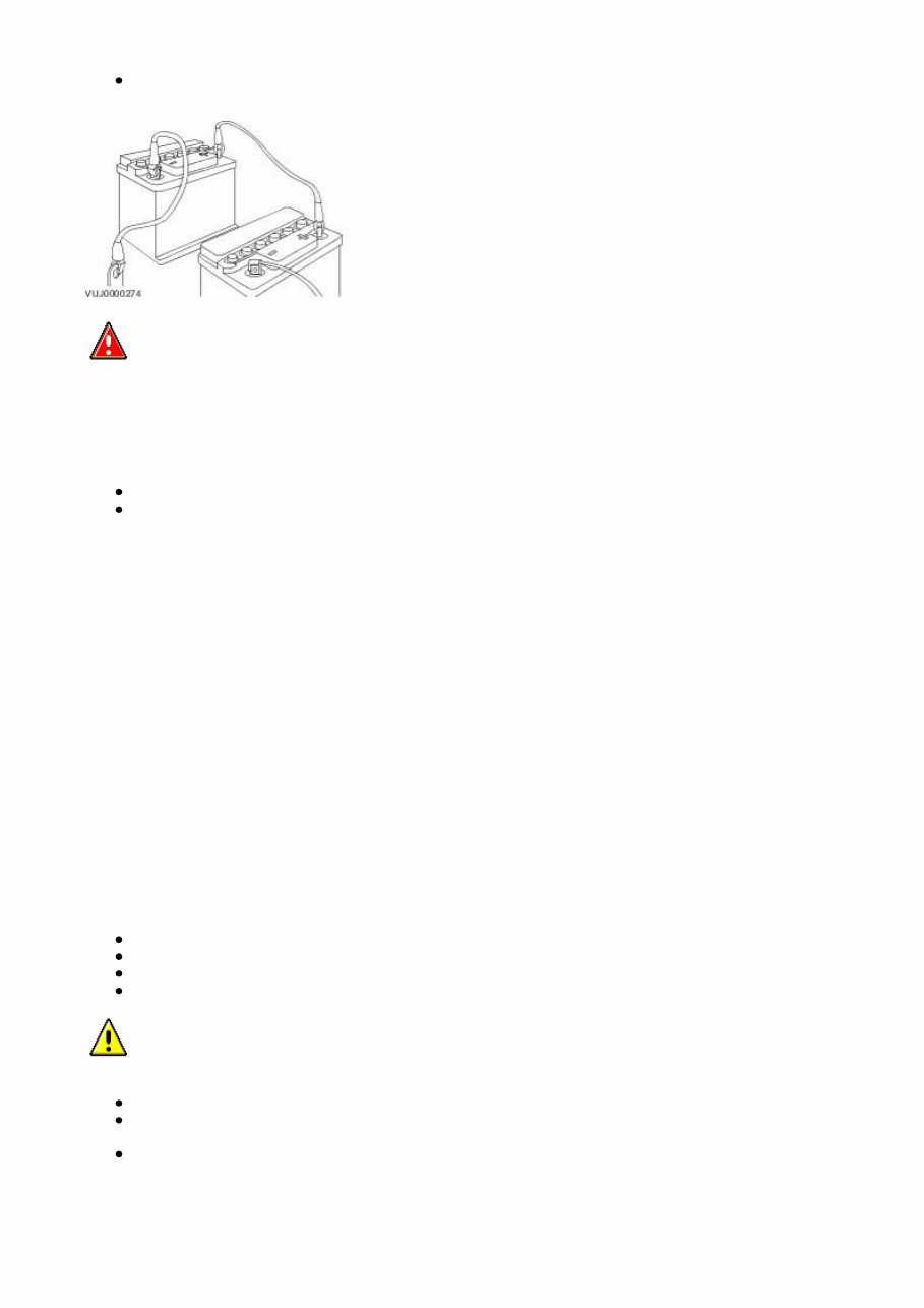
systems. It must be noted that, when using these devices, the vehicle electrical system is still live albeit with a reduced current flow. NOTE: Before disconnecting the battery make sure that the radio receiver/cassette player/mini disc player and compact disc player keycodes are known and, that no data is required from the engine control module (ECM) as battery disconnection will erase any fault codes and idle/drive values held in the Keep Alive Memory (KAM). It is not necessary to disconnect or remove electronic control modules. Always disconnect the battery before commencing repair operations which require: The vehicle to be jacked up Work on the engine Work underneath the vehicle Arc welding Alternatively a Radio Code Saver may be used. With the battery disconnected, a Radio Code Saver will allow sufficient current to pass to maintain the radio receiver/cassette player/mini disc player and compact disc player memory, operate the clock and supply the door operated interior lights while isolating the battery in the event of a short circuit. Reconnecting the Battery WARNING: If the battery has been on bench charge the cells may be giving off explosive hydrogen gas. Avoid creating sparks, and if in doubt cover the vent plugs or covers with a damp cloth. Always make sure that all electrical systems are switched OFF before reconnecting the battery to avoid causing sparks or damage to sensitive electrical equipment. Always reconnect the battery positive lead first and the negative last, ensuring that there is a good electrical contact and the battery terminals are secure. Restart the clock (where fitted) and set it to the correct time. Re - enter the radio receiver/cassette player/mini disc player and compact disc player keycodes and preset' frequencies, if known. Following reconnection of the battery, the engine should be allowed to idle until it has reached normal operating temperature as the stored idle and drive values contained within the ECM have been lost. Allow the vehicle to idle for a further three minutes. Drive the vehicle at constant speeds of approximately 48 km/h (30 mph), 64 km/h (40 mph), 80 km/h (50 mph), 96 km/h (60 mph) and 112 km/h (70 mph) for three minutes each. This may cause a driveability concern if the procedure is not carried out. This will allow the ECM to relearn idle values. Connecting a Slave Battery Using Jump Leads WARNING: If the slave battery has recently been charged and is gassing, cover the vent plugs or covers with a damp cloth to reduce the risk of explosion should arcing occur when connecting the jump leads. CAUTION: A flat battery condition may have been caused by an electrical short circuit. If this condition exists there will be an apparently live circuit on the vehicle even when all normal circuits are switched off. This can cause arcing when the jump leads are connected. CAUTION: Whilst it is not recommended that the vehicle is jump started, it is recognized that this may occasionally be the only practical way to mobilize a vehicle. In such an instance the discharged battery must be recharged immediately after jump starting to avoid permanent damage. Always make sure that the jump leads are adequate for the task. Heavy duty cables must be used. Always make sure that the slave battery is of the same voltage as the vehicle battery. The batteries must be
connected in parallel. Always make sure that switchable electric circuits are switched off before connecting jump leads. This reduces the risk of sparks occurring when the final connection is made. WARNING: Make sure that the ends of the jump leads do not touch each other or ground against the vehicle body at any time while the leads are attached to the battery. A fully charged battery, if shorted through jump leads, can discharge at a rate well above 1000 amps causing violent arcing and very rapid heating of the jump leads and terminals, and can even cause the battery to explode. Always connect the jump leads in the following sequence. Slave battery positive first then vehicle battery positive. Slave battery negative next and then vehicle ground at least, 300 mm (12 in) from the battery terminal e.g. engine lifting bracket. Always reduce the engine speed to idle before disconnecting the jump leads. Before removing the jump leads from the vehicle that had the discharged battery, switch on the heater blower (high) or the heated rear screen, to reduce the voltage peak when the leads are removed. Always disconnect the jump leads in the reverse order to the connecting sequence and take great care not to short the ends of the leads. Do not rely on the alternator to restore a discharged battery. For an alternator to recharge a battery, it would take in excess of 8 hours continuous driving with no additional loads placed on the battery. Component Cleaning To prevent ingress of dirt, accumulations of loose dirt and greasy deposits should be removed before disconnecting or dismantling components or assemblies. Components should be thoroughly cleaned before inspection prior to reassembly. Cleaning Methods: Dry Cleaning Removal of loose dirt with soft or wire brushes. Scraping dirt off with a piece of metal or wood. Wiping off with a rag. CAUTION: Compressed air is sometimes wet so use with caution, especially on hydraulic systems. Blowing dirt off with compressed air. (Eye protection should be worn when using this method). Removal of dry dust using vacuum equipment. This method should always be used to remove friction lining material dust (asbestos particles). Steam Cleaning Calibration of Essential Measuring Equipment
WARNING: Failure to comply may result in personal injury or damage to components. It is of fundamental importance that certain essential equipment e.g. torque wrenches, multimeters, exhaust gas analysers, rolling roads etc., are regularly calibrated in accordance with the manufacturers instructions. Use of Control Modules Control modules may only be used on the vehicle to which they were originally fitted. Do not attempt to use or test a control module on any other vehicle. Functional Test On completion of a maintenance procedure, a thorough test should be carried out, to make sure that the relevant vehicle systems are working correctly. Preparation Before disassembly, clean the surrounding area as thoroughly as possible. When components have been removed, blank off any exposed openings using grease-proof paper and masking tape. Immediately seal fuel, oil and hydraulic lines when separated, using plastic caps or plugs, to prevent loss of fluid and the entry of dirt. Close the open ends of oilways, exposed by component removal, with tapered hardwood plugs or readily visible plastic plugs. Immediately a component is removed, place it in a suitable container; use a separate container for each component and its associated parts. Before dismantling a component, clean it thoroughly with a recommended cleaning agent; check that the agent will not damage any of the materials within the component. Clean the bench and obtain marking materials, labels, containers and locking wire before dismantling a component. Dismantling Observe scrupulous cleanliness when dismantling components, particularly when parts of the brake, fuel or hydraulic systems are being worked on. A particle of dirt or a fragment of cloth could cause a dangerous malfunction if trapped in these systems. Clean all tapped holes, crevices, oilways and fluid passages with compressed air. Do not permit compressed air to enter an open wound. Always use eye protection when using compressed air. Make sure that any O-rings used for sealing are correctly refitted or renewed if disturbed. Mark mating parts to make sure that they are replaced as dismantled. Whenever possible use marking materials which avoid the possibilities of causing distortion or the initiation of cracks, which could occur if a center punch or scriber were used. Wire together mating parts where necessary to prevent accidental interchange (e.g roller bearing components). Tie labels on to all parts to be renewed and to parts requiring further inspection before being passed for reassembly. Place labelled parts and other parts for rebuild in separate containers. Do not discard a part which is due for renewal until it has been compared with the new part, to make sure that the correct part has been obtained. Inspection Before inspecting a component for wear or performing a dimensional check, make sure that it is absolutely clean; a slight smear of grease can conceal an incipient failure. When a component is to be checked dimensionally against figures quoted for it, use the correct equipment (surface plates, micrometers, dial gauges etc.) in serviceable condition. The use of makeshift equipment can be dangerous. Reject a component if its dimensions are outside the limits quoted, or if damage is apparent. A part may be refitted if its critical dimension is exactly to the limit size and it is otherwise satisfactory. Use Plastigauge 12 Type PG-1 for checking bearing surface clearance, e.g. big end bearing shell to crank journal. Instructions for the use of Plastigauge and a scale giving bearing clearances in steps of 0,0025 mm (0.0001 in) are supplied with the package. On-Board Diagnostics (OBD) This vehicle uses programmed electronic control systems to provide engine management and emission regulation, automatic transmission operation and anti-lock braking control. These control systems are integral with the On-Board Diagnostics (OBD) facility which is used in conjunction with either the Jaguar approved diagnostic system or the more restricted scan tools. The OBD information in this manual provides diagnostic and rectification procedures for emission related electrical and mechanical systems. The information is intended to facilitate fault diagnosis and the subsequent rectification of the vehicle without recourse to the Jaguar approved diagnostic system.
The manual covers the following OBD topics: General Information Engine Management System Automatic Transmission Anti-lock Braking System Each section comprises one or more of the following sub-sections as required. The Description and Operation sub-section includes: A general illustration and parts list to help the identification of the particular system or component. A brief description of the system operating characteristics and monitoring procedure accompanied by a component illustration. Additional information, where appropriate, is provided in the form of component calibrations, characteristics and cross sectional views. A localized circuit diagram is included to provide circuit identification, connectors, splices, fuses, wire gauge and colors. See Circuit Diagrams. The Diagnosis and Testing sub-section is dedicated to fault analysis and rectification, and includes: Recommended special tools. Symptom chart; a chart containing all relevant Diagnostic Trouble Codes (DTC), their possible causes and an indication of the appropriate test. Specific pinpoint test(s), designed so that fault diagnosis can be carried out in a logical and efficient manner. The Removal and Installation sub-section covers: Removal procedure(s), formatted in the recommended sequence. Illustrated guide to the use of special tools. Illustrations to support the relevant text. Installation procedure as above and including special recommendations for processes, lubricants and tightening torques. Circuit Diagrams To understand the relationship between the vehicle electrical system and the system circuit diagrams, Refer to the Electrical Guide. In the interest of clarity, single lines may represent multiple wires. Refer to the color code (1st alpha) followed by the wire reference (numeric/alpha/numeric) to trace origin and destination. e.g. BW 647B002. BW (black with white trace) 647 (wire reference) B002 (stage from origin). Glossary of Terms This glossary of terms is intended to cover mainly emissions-related (to SAE J 1930) terminology, and other abbreviations that may be used in this manual. The required term may be looked-up in the left-hand column, and subsequent columns give the standard acronym, unit or abbreviation, and definition. Term(s) Acronym / Unit / Abbreviation Definition Accelerator Pedal AP Accelerator Pedal Position Sensor APP Is a multitrack sensor which inputs the drivers demand into the engine control module (ECM) After Bottom Dead Center ABDC Event occurring after BDC After Top Dead Center ATDC Event occurring after TDC Airbag / Supplementary Restraint System Airbag, SRS Airbag restraint system for driver and front seat passenger
If you are in need of a repair manual for your 2001 Jaguar S-Type, look no further. Our accessible repair manual is a cost-effective and convenient alternative to traditional paper manuals. Whether you are a professional mechanic or a DIY enthusiast, this manual covers all the essential service and repair information for the Jaguar S-Type.
Gone are the days of purchasing expensive traditional service manuals in book format. Our digital manual provides the same valuable information at a fraction of the cost, making it easier and more affordable to access the necessary details for maintaining and repairing your vehicle.
Whether you are tackling brake repairs, suspension component replacements, engine troubleshooting, or standard maintenance tasks, this repair manual is an invaluable resource. It contains comprehensive guidance on brakes, engine, suspension, steering, drivetrain, electrical systems, heating, air conditioning, and more, empowering you to address any issue with confidence.
By utilizing this repair manual , you can save a significant amount of money on vehicle maintenance and repairs. Instead of relying on costly professional mechanics, take matters into your own hands and leverage the detailed instructions provided in the 2001 Jaguar S-Type repair manual to efficiently address any automotive concern.
Our manual is designed for ease of use and compatibility with various devices, including Windows, Mac computers, smartphones, and tablets, ensuring that you can access the essential information whenever and wherever you need it.