WORKSHOP MANUAL RODEO (UE) FOREWORD This manual includes special notes, important points, service data, precautions, etc. that are needed for the maintenance, adjustments, service, removal and installation of vehicle components. All information, illustrations and specifications contained in this manual are based on the latest product information available at the time of publication. All rights are reserved to make changes at any time without notice. Arrangement of the material is shown in the table of contents on the right-hand side of this page. A black spot on the first page of each section can be seen on the edge of the book below each section title. These point to a more detailed table of contents preceding each section. This manual applies to 1999 models. SECTION TABLE OF CONTENTS GENERAL INFORMATION 0A General Information 0B Maintenance and Lubrication HEATING, VENTILATION AND AIR CONDITIONING 1A HVAC System STEERING 2A Power-Assisted System SUSPENSION 3C Front Suspension 3D Rear Suspension 3E Wheel and Tire System DRIVELINE/AXLE 4A1 Differential 4A2 Differential 4B Driveline Control System 4C Drive Shaft System 4D Transfer Case BRAKE 5A Brake Control System 5B Anti-Lock Brake System 5C Power-Assisted Brake System 5D1 Parking Brake System (4x4 model) 5D2 Parking Brake System (4x2 model) HEC ENGINE 6A Engine Mechanical 6B Engine Cooling 6C Engine Fuel 6D1 Engine Electrical 6D2 Ignition System 6D3 Starting and Charging System 6E Driveability and Emissions 6F Engine Exhaust 6G Engine Lubrication 6H Engine Speed Control System 6J Induction TRANSMISSION 7A Automatic Transmission 7A1 Transmission Control System 7B Manual Transmission 7C Clutch BODY AND ACCESSORIES 8A Lighting System 8B Wiper/Washer System 8C Entertainment 8D Wiring System 8E Meter and Gauge 8F Body Structure 8G Seats 8H Security and Locks 8I Sun Roof/Convertible Top 8J Exterior/Interior Trim RESTRAINTS 9A Seat Belt System 9J Supplemental Restraint System (Air Bag System) 9J1 Restraint Control System CONTROL SYSTEM 10A Cruise Control System 6VD1 6A 6B 6C 6D1 6D2 6D3 6E 6F 6G 6H 6J
0A–1 GENERAL INFORMATION RODEO GENERAL INFORMATION CONTENTS General Information 0A . . . . . . . . . . . . . . . . . . . . . Maintenance and Lubrication 0B . . . . . . . . . . . . . General Information CONTENTS General Repair Instruction 0A–1 . . . . . . . . . . . . . . . . Illustration Arrows 0A–2 . . . . . . . . . . . . . . . . . . . . . . . Identification 0A–3 . . . . . . . . . . . . . . . . . . . . . . . . . . . . Theft Prevention Standard 0A–5 . . . . . . . . . . . . . . . . Lifting Instructions 0A–10 . . . . . . . . . . . . . . . . . . . . . . . Standard Bolts Torque Specifications 0A–12 . . . . . . Abbreviations Charts 0A–13 . . . . . . . . . . . . . . . . . . . . Service Parts Identification Plate 0A–14 . . . . . . . . . . General Repair Instruction 1. If a floor jack is used, the following precautions are recommended. Park vehicle on level ground, “block” front or rear wheels, set jack against the recommended lifting points (see “Lifting Instructions” in this section), raise vehicle and support with chassis stands and then perform the service operations. 2. Before performing service operations, disconnect ground cable from the battery to reduce the chance of cable damage and burning due to short circuiting. 3. Use a cover on body, seats and floor to protect them against damage and contamination. 4. Brake fluid and anti–freeze solution must be handled with reasonable care, as they can cause paint damage. 5. The use of proper tools and recommended essential and available tools, where specified, is important for efficient and reliable performance of service repairs. 6. Use genuine Isuzu parts. 7. Used cotter pins, plastic clips, gaskets, O–rings, oil seals, lock washers and self–locking nuts should be discarded and new ones should be installed, as normal function of the parts cannot be maintained if these parts are reused. 8. To facilitate proper and smooth reassembly operation, keep disassembled parts neatly in groups. Keeping fixing bolts and nuts separate is very important, as they vary in hardness and design depending on position of installation. 9. Clean the parts before inspection or reassembly. Also clean oil ports, etc. using compressed air, and make certain they are free from restrictions. 10. Lubricate rotating and sliding faces of the parts with oil or grease before installation. 11.When necessary, use a sealer on gaskets to prevent leakage. 12. Carefully observe all specifications for bolt and nut torques. 13. When removing or replacing parts that require refrigerant to be discharged from the air conditioning system, be sure to use the Vehicle Refrigerant Recovery and Recycling Equipment (VRRRE) to recover and recycle Refrigerant–134a. 14. When a service operation is completed, make a final check to be sure the service has been done properly and the problem has been corrected. 15. SUPPLEMENTAL RESTRAINT SYSTEM The vehicle is equipped with a Supplemental Restraint System (SRS) – Air Bags. This system is not to be serviced without consulting the appropriate service information. Consult Section 9J “SRS System” if work is to be done on the front of the vehicle such as bumper, sheet metal, seats, wiring, steering wheel or column. Also review SRS system information if any arc welding is to be done on the vehicle. The SRS system equipped vehicle can be identified by: 1. “AIR BAG” warning light on the instrument cluster. 2. A Code “J” for fifth digit of Vehicle Identification Number.
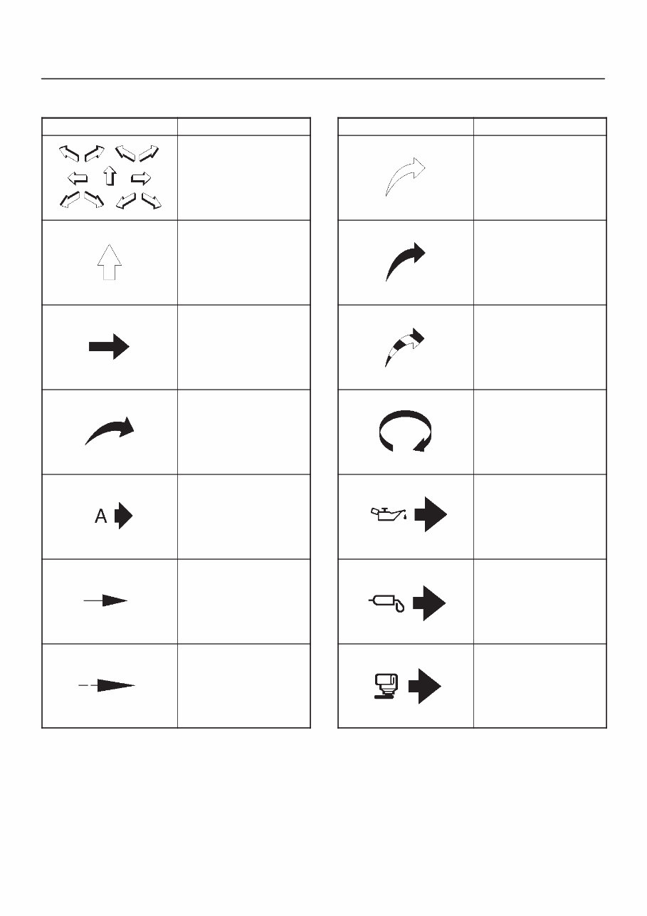
0A–2 GENERAL INFORMATION Illustration Arrows Arrows are designed for specific purposes to aid your understanding of technical illustrations. Arrow Type Application Front of vehicle Up Side Task Related View Detail View Angle Dimension (1:2) Sectioning (1:3) Arrow Type Application f Ambient/Clean air flow f Cool air flow f Gas other than ambient air f Hot air flow f Ambient air mixed with another gas f Can indicate temperature change Motion or direction Lubrication point oil or fluid Lubrication point grease Lubrication point jelly
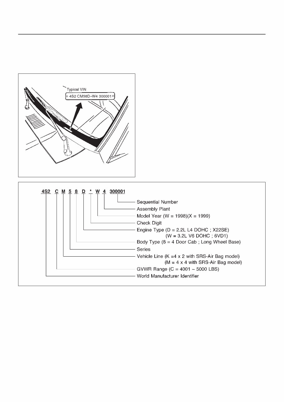
0A–3 GENERAL INFORMATION Identification Vehicle Identification Number (VIN) This is the legal identification of the vehicle. it is located on the left bottom of the windshield. It can be easily seen through the windshield from outside the vehicle. 710RW003 F00RX002
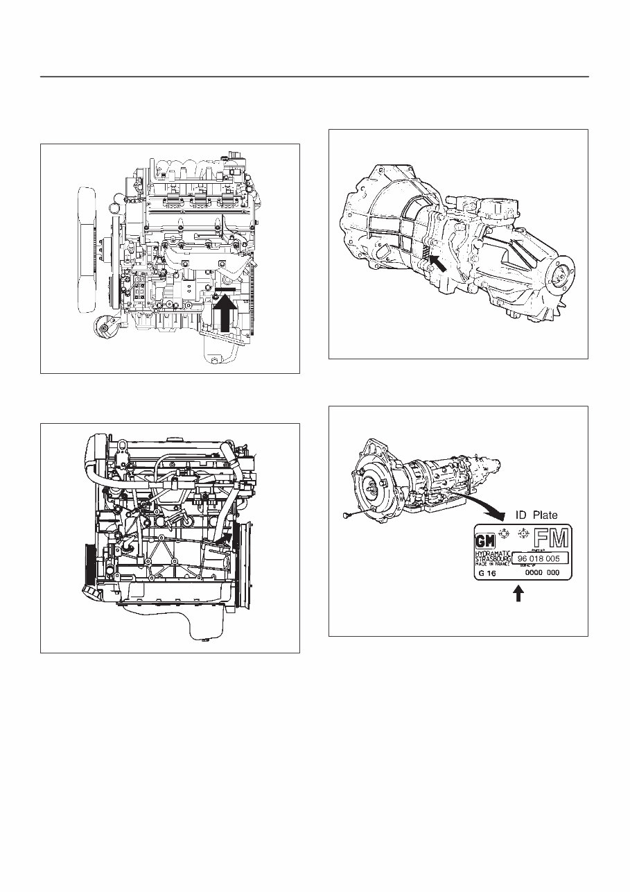
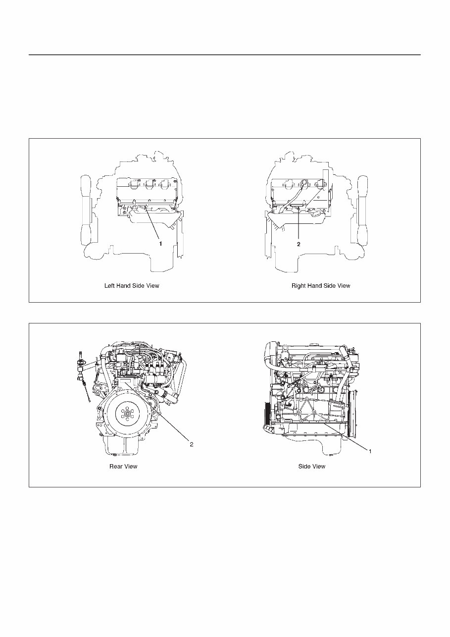
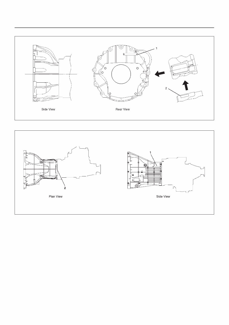
0A–4 GENERAL INFORMATION Engine Serial Number f 6VD1 Engine The gasoline engine serial number is stamped on the left rear lower area of the cylinder block above the starter. F06RW001 f X22SE Engine The gasoline engine serial number is stamped on the rear end raised area of the cylinder block left side. 035RW022 Transmission Serial Number Manual : Stamped on the left side of the transmission intermediate plate. 220RS025 Automatic : Stamped on the identification plate, located on the left side of the transmission above the mode switch. 240RW019
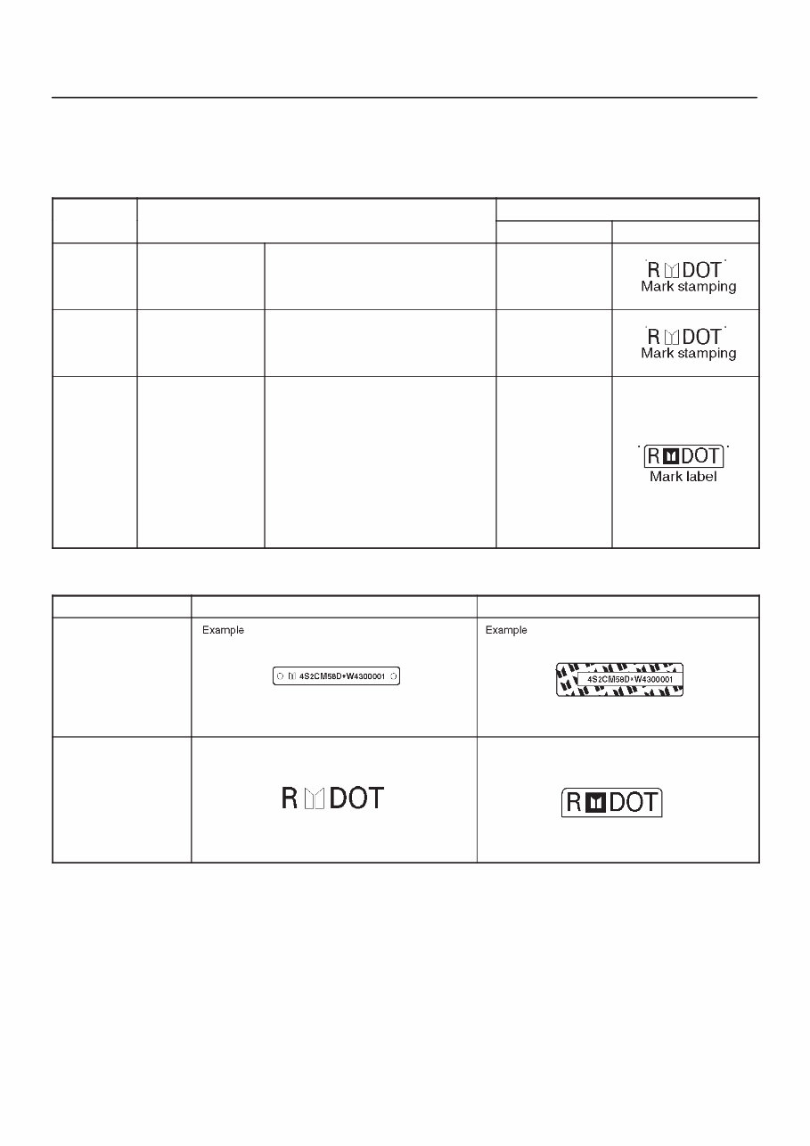
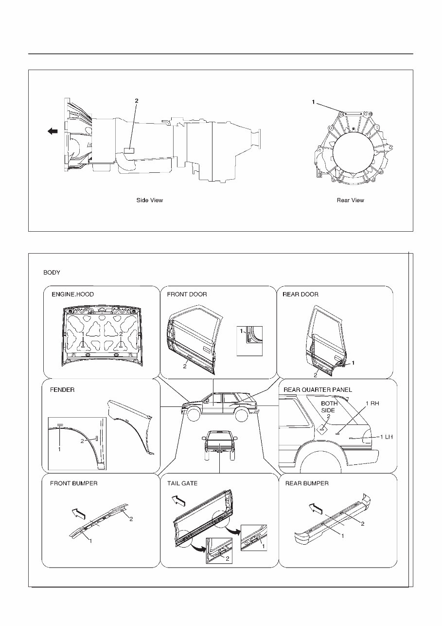
0A–5 GENERAL INFORMATION Theft Prevention Standard The 11 major components listed below will be marked with 17 digit VIN at the stage of production. In addition its service parts will be marked with manufacturer’s trade mark, “R” mark and “DOT” mark. Reference COMPONENT INDICATION Figure No. COMPONENT PRODUCTION SERVICE PARTS 0A-10 ENGINE 1– 6VD1 – X22SE VIN plate 0A-11 TRANSMISSION 2– Manual transmission – Automatic transmission VIN plate 0A-11 BODY 3– Engine hood 4– Front door 5– Rear door 6– Fender 7– Rear Quarter panel 8– Front bumper 9– Back door left side 10– Back door right side 11– Rear bumper VIN label Anti Theft Stamping/Plate/Label STAMPING/PLATE LABEL PRODUCTION SERVICE PARTS
0A–6 GENERAL INFORMATION Anti Theft Stamping/Label/Plate Location The stamping, label and plate locations are indicated by arrows in the illustration below. NOTE: 1. VIN plate locations for production. 2. Stamping locations for service parts. Engine (6VD1) 901RW080 Engine (X22SE) 035RW025
0A–7 GENERAL INFORMATION Manual Transmission (TREMEC T5) 240RW020 Manual Transmission (MUA) 901RW081
0A–8 GENERAL INFORMATION Automatic Transmission (THM) 901RW082–1 Body 604RW023
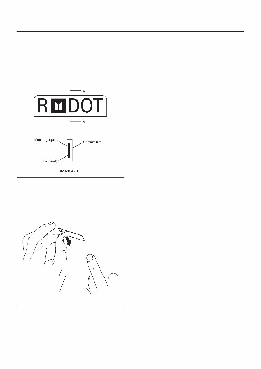
0A–9 GENERAL INFORMATION Body Label Instructions Do not peel off the masking tape until completion of paint work when replacing these parts, as the tape is affixed on the label attached to service parts for body of the anti–theft component. NOTE: Be sure to pull off the masking tape after paint work has been completed. Do not attempt to remove this label for any reason. 901RW083 Precautions in pulling off the masking tape 1. Use only your finger nail or a similar blunt instrument to peel off the masking tape. Use of a sharp object will damage the underlying anti–theft label. 2. Be careful not to damage the paint around the label. 901RW084
When it comes to fixing problems in your vehicle, the 2000 Isuzu Wizard Service and Repair Manual is an invaluable resource. Whether you're a professional mechanic or a DIY enthusiast, this manual provides comprehensive instructions and procedures for addressing issues in your ride.
With over 20 years of experience in auto repair and body work, including 10 years as a Mercedes mechanic, the manual not only offers technical guidance but also expert advice on resolving car problems. Customer support is available via email, ensuring that all your questions are answered within a 24-hour period.
Auto Repair Manuals are essential for immediate car repairs and the long-term maintenance of your vehicle. They contain detailed technical data, diagrams, a complete list of car parts, and images, making it easy for even novice mechanics to follow the step-by-step guides.
The repair manual covers all models and repairs from A-Z, providing precise instructions, diagrams, illustrations, wiring schematics, and specifications to facilitate easy vehicle repairs. It eliminates the need to flip through multiple books, as you can print only the necessary pages and diagrams. The manual is compatible with Windows Vista 32 and 64, XP, ME, 98, NT, 2000, and Mac, ensuring accessibility for all users.
From engine and mechanical components to electrical systems and more, the manual includes comprehensive information to service and repair your vehicle effectively. It is printable, allowing you to keep a clean digital copy on your PC and print specific pages as needed.
Compatible with all versions of Windows and Mac, the manual is a time-saving resource that empowers you to handle car repairs independently. It provides in-depth knowledge and keeps you up-to-date with the latest maintenance procedures, reducing your reliance on professional mechanics for simple repairs.
With the 2000 Isuzu Wizard Service and Repair Manual, you can confidently tackle car maintenance and repairs, ensuring the longevity and performance of your vehicle.
Maintenance
Engine
Control System
Mechanical
Fuel Service Specifications
Emission Control
Intake Exhaust Cooling
Lube
Ignition Starting Charging
Auto Transmission Clutch
Manual Transmission
Transfer Propeller Shaft
Drive Shaft
Differential
Axle Suspension
Tire & Wheel
Brake Control
Brake
Parking Brake
Steering Column
Power Steering
Air Condition
Suppl Restraint System
Seat Belt
Engine Immobilizer
Cruise Control
Wiper & Washer
Door Lock
Meter Audio/Visual
Horn
Windshield/Glass Mirror
Instrument Panel
Seat
Engine Hood/ Door
Exterior & Interior
Electrical
Multiplex/ Can Communication
And much more...
Get your hands on the 2000 Isuzu Wizard Service and Repair Manual and take control of your car maintenance and repair needs.




 Lifetime Access




