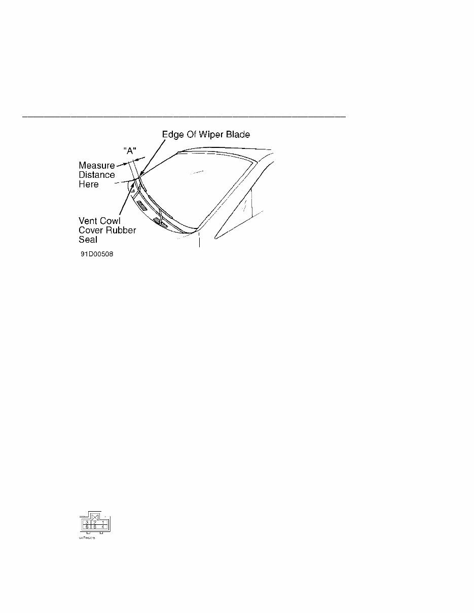
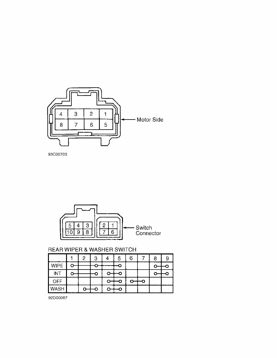
WIPER/WASHER SYSTEM - EARLY PRODUCTION Article T "A" ............................................ 1.80 (45) Fig. 1: Adjusting Front Wiper Arms Courtesy of Isuzu Motor Co. REAR WIPER ARM ADJUSTMENT Ensure wiper motor is in auto stop position before adjusting wiper arm assembly. Tighten wiper arm nut to 12-17 ft. lbs. (16.3-23.0 N.m). No further adjustment is available from manufacturer. TESTING FRONT WIPER MOTOR TEST 1) To check low speed operation, connect positive battery terminal to terminal No. 2 and negative battery terminal to terminal No. 3 of wiper motor connector. See Fig. 2. Wiper motor should operate at low speed. 2) To check high speed operation, connect positive battery terminal to terminal No. 1 and negative battery terminal to terminal No. 3 of wiper motor connector. Wiper motor should operate at high speed. 3) To check auto stop operation, operate wiper motor at low speed. See step 1). Disconnect positive battery terminal from terminal No. 2. Connect battery positive terminal to wiper motor terminal No. 6. Connect a jumper wire between terminals No. 2 and 5. Wiper motor should operate at low speed, then stop at auto stop position. Fig. 2: Wiper Motor Or Intermittent Relay Connector Terminals Courtesy of Isuzu Motor Co. FRONT WIPER SWITCH TEST
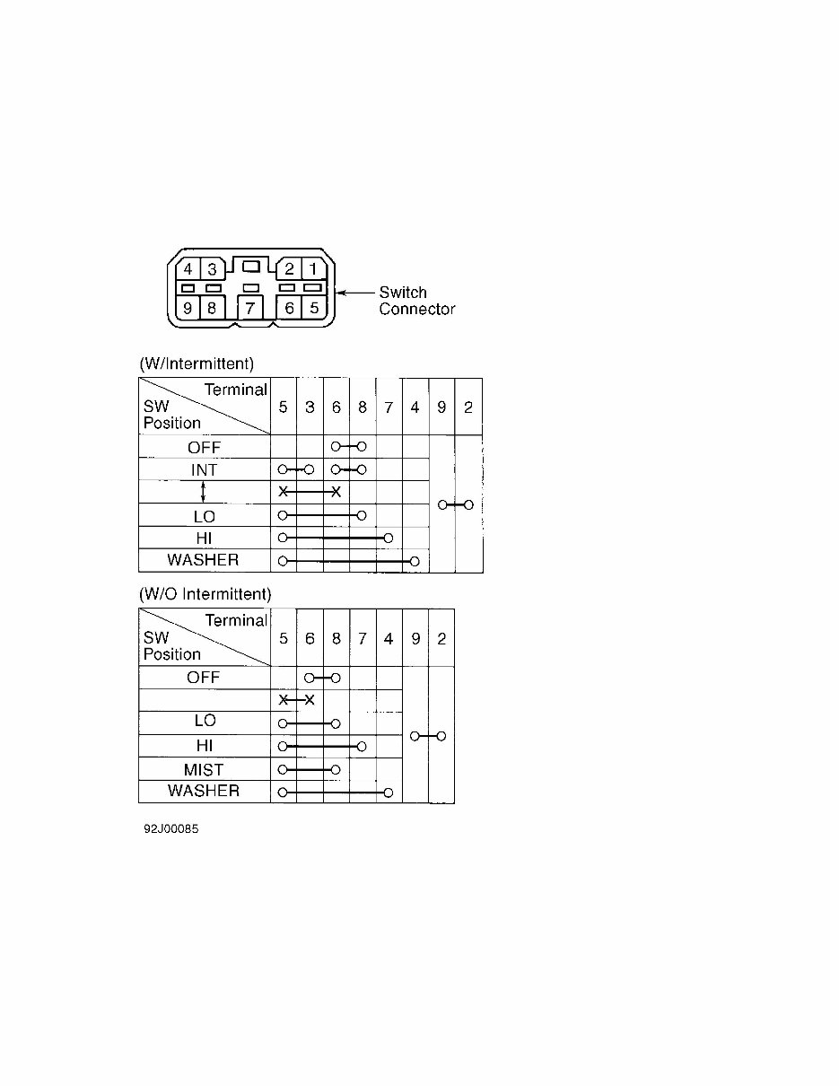
WIPER/WASHER SYSTEM - EARLY PRODUCTION Article Text (p. 3 Disconnect wiper switch connector. Using ohmmeter, check continuity between specified terminals. See Fig. 3. Replace switch if continuity does not exist between specified terminals. Fig. 3: Checking Front Wiper Switch Courtesy of Isuzu Motor Co. INTERMITTENT RELAY TEST Intermittent relay is located in fuse/relay box in engine compartment, on passenger side. Disconnect intermittent relay connector. Apply battery voltage (positive) to relay terminals No. 3 and 6. See Fig. 2. Connect ground to relay terminal No. 1. Using a voltmeter, ensure battery voltage is present (intermittent) at relay terminal No. 2. If battery voltage is not present, replace relay.
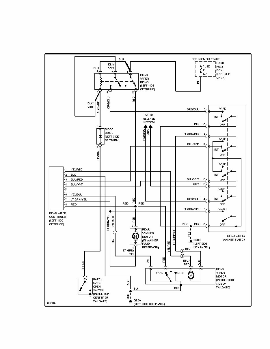
WIPER/WASHER SYSTEM - EARLY PRODUC between specified relay terminals. See REAR WIPER RELAY CONTINUITY table. REAR WIPER RELAY CONTINUITY TABLE Terminals No. (1) Continuity (Wire Colors) 1 & 2 (Blue & Red) ................................... Yes 3 & 4 (Black/White & Orange/Blue) ..................... No 1 & 2 (2) (Blue & Red) ................................ No 3 & 4 (2) (Black/White & Orange/Blue) ................ Yes (1) - Use wire colors for terminal identification. (2) - Battery voltage applied between wiper relay terminals No. 5 (Blue wire) and No. 6 (Black/White wire). REMOVAL & INSTALLATION FRONT WIPER MOTOR Removal 1) Disconnect electrical connector from wiper motor. Remove wiper motor retaining screws. Disconnect wiper motor from wiper linkage at ball joint, and remove wiper motor. 2) If linkage assembly is to be removed, remove cap from wiper arm. Remove wiper arm nut and wiper arm. Remove vent cowl cover. Remove wiper linkage through access hole. Installation 1) To install, reverse removal procedure. If crank arm was removed from wiper motor, ensure wiper motor is in park position before installing crank arm on wiper motor. 2) Tighten wiper motor crank arm nut to 11 ft. lbs. (15 N.m). When installing wiper arms, ensure wiper arms are properly positioned. See FRONT WIPER ARM ADJUSTMENT under ADJUSTMENTS. Tighten wiper arm nuts to 11 ft. lbs. (15 N.m). REAR WIPER MOTOR Removal & Installation Disconnect negative battery terminal. Drop tailgate down. Remove inner access panel from tailgate. Loosen wiper motor mounting bolts. Disconnect wiper linkages and electrical connectors. Remove wiper motor. To install, reverse removal procedure. REAR WIPER SWITCH Removal & Installation Disconnect negative battery terminal. Using a screwdriver, pry rear wiper switch from instrument panel. Disconnect electrical
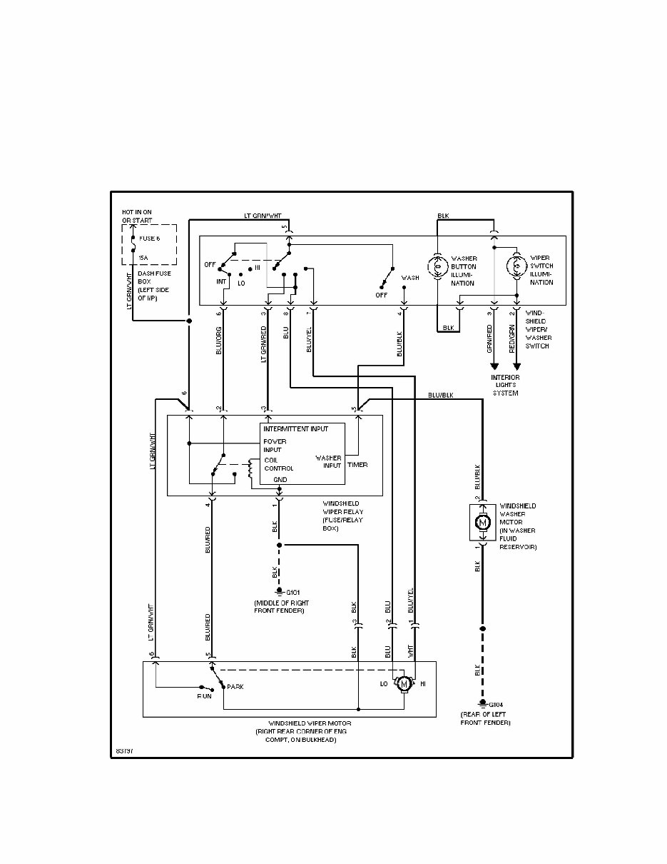
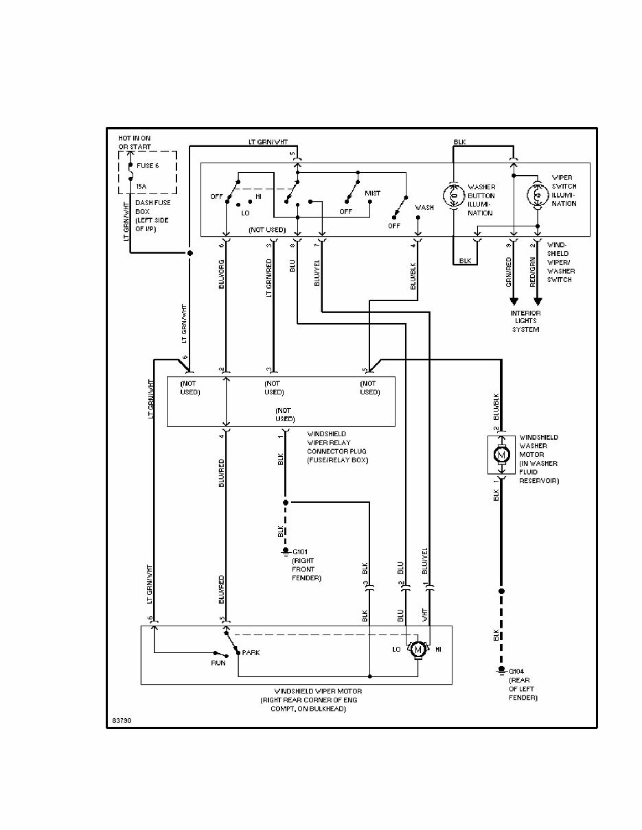
WIPER/WASHER SYSTEM - EARLY PRODUC connector from back of switch. To install, reverse removal procedure. WIRING DIAGRAMS Fig. 6: Wiper/Washer System Wiring Diagram (W/Intermittent Wipers)
The 1995 ISUZU RODEO Service and Repair Manual is the ultimate guide for maintaining and fixing your vehicle. Designed specifically for the 1995 ISUZU RODEO model, this comprehensive manual provides step-by-step instructions and detailed diagrams to help you with any service or repair task.
Whether you are a professional mechanic or a do-it-yourself enthusiast, this manual will be your go-to resource. It covers a wide range of topics, including engine maintenance, electrical system troubleshooting, brake repairs, transmission servicing, and much more.
With the 1995 ISUZU RODEO Service and Repair Manual, you can save time and money by doing the repairs yourself. No more costly visits to the mechanic or dealership. Simply follow the clear and concise instructions provided in this manual, and you can get your vehicle back on the road in no time.
Step-by-step instructions for all service and repair tasks
Detailed diagrams and illustrations to aid understanding
Comprehensive coverage of engine, electrical system, brakes, transmission, and more
Suitable for professional mechanics and DIY enthusiasts
Save time and money by doing the repairs yourself
Don't let car troubles slow you down. Get the 1995 ISUZU RODEO Service and Repair Manual today and take control of your vehicle's maintenance and repairs.