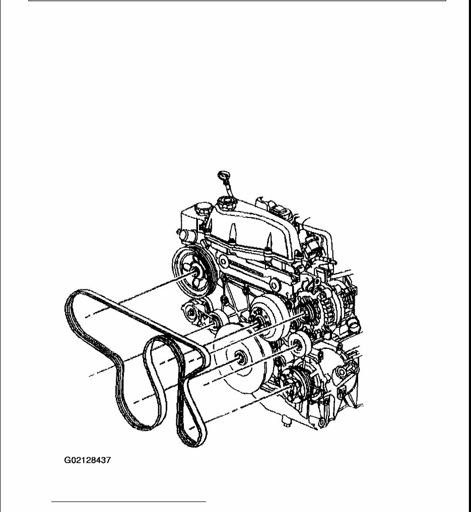
REPAIR INSTRUCTIONS DRIVE BELT REPLACEMENT Removal Procedure 1. Install 3/8 inch breaker bar on the drivebelt tensioner arm and turn the breaker bar clockwise enough to relieve the tension on the drivebelt. 2. Remove the drivebelt. 3. Release the tension on the tensioner arm. Fig. 83: Removing/Installing Drive Belt Courtesy of GENERAL MOTORS CORP.
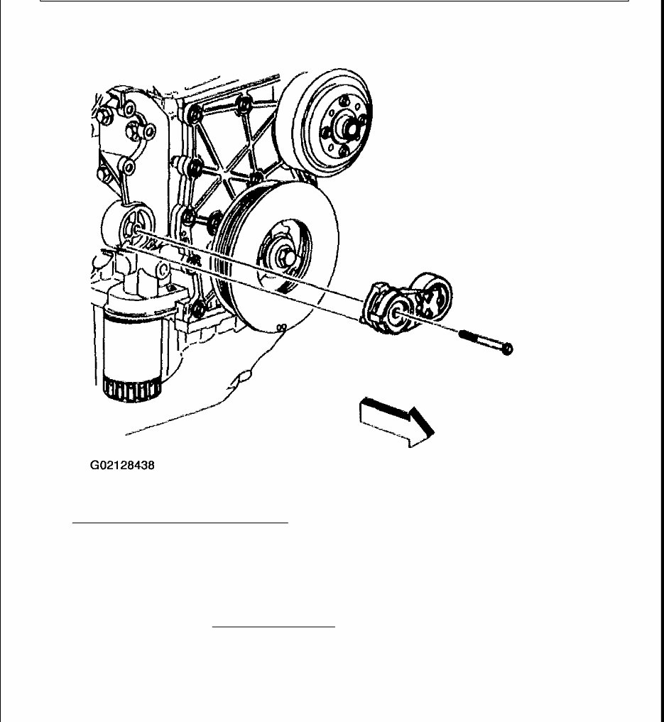
Installation Procedure 1. Route the drivebelt over all the pulleys except the drivebelt tensioner pulley. 2. Install the 3/8 inch breaker bar on the drivebelt tensioner arm and turn the breaker bar clockwise. 3. Install the drivebelt over the drivebelt tensioner pulley. 4. Slowly release the tension to the drivebelt tensioner arm. 5. Inspect for proper installation of the drivebelt on the pulleys. DRIVE BELT TENSIONER REPLACEMENT Removal Procedure 1. Remove the drivebelt. Refer to DRIVE BELT REPLACEMENT . 2. Inspect the drivebelt. Change the drivebelt as necessary. 3. Using a wrench loosen and remove the drivebelt tensioner bolt. 4. Remove the drivebelt tensioner.
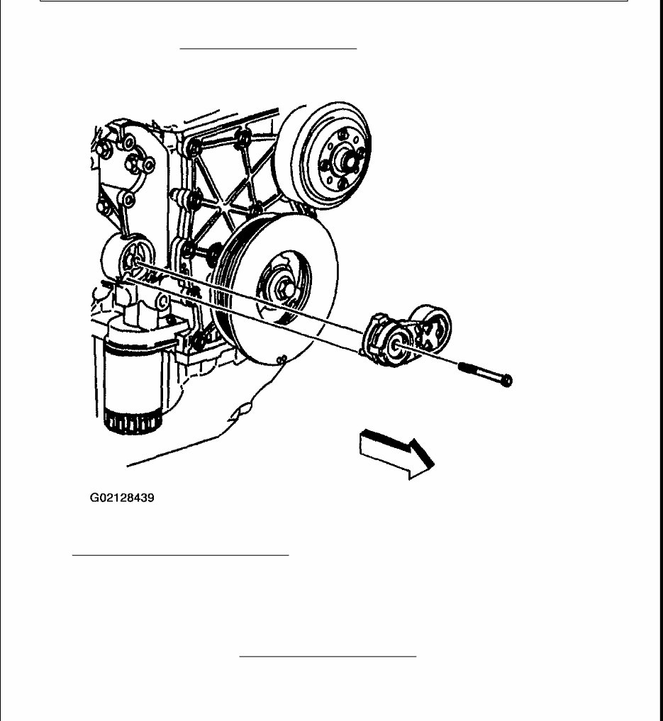
Fig. 84: Removing Drivebelt Tensioner Courtesy of GENERAL MOTORS CORP. Installation Procedure 1. Install the drive belt tensioner. 2. Install the drive belt tensioner bolt. Tighten Tighten the drive belt tensioner bolt to 50 N.m (37 lb ft). NOTE: Refer to FASTENER NOTICE in Cautions and Notices.
3. Install the drive belt DRIVE BELT REPLACEMENT . Fig. 85: Installing Drive Belt Tensioner Courtesy of GENERAL MOTORS CORP. DRIVE BELT IDLER PULLEY REPLACEMENT Removal Procedure 1. Remove the drive belt. Refer to DRIVE BELT REPLACEMENT . 2. Remove the idler pulley bolt from the idler pulley bracket. 3. Remove idler pulley. Installation Procedure
1. Install the idler pulley and secure the pulley with the bolt. Tighten Tighten the idler pulley bolt to 50 N.m (37 lb ft). 2. Install the drive belt. Refer to DRIVE BELT REPLACEMENT . ENGINE MOUNT INSPECTION Front Engine Mount 1. Install a pole jack underneath the oil pan. 2. Insert a block of wood between the engine oil pan and the pole jack. 3. Raise the jack until the wooden block contacts the engine oil pan. 4. Raise the engine in order to place a slight tension on the rubber cushion. Observe both mounts while raising the engine. NOTE: Refer to FASTENER NOTICE in Cautions and Notices. NOTE: Broken or deteriorated mounts can cause misalignment and destruction of certain drive train components. When a single mount breaks, the remaining mounts are subjected to abnormally high stresses.
Fig. 86: Installing Pole Jack Underneath Oil Pan Courtesy of GENERAL MOTORS CORP. 5. Replace the mounts if any of the following conditions exist: Hard rubber surface covered with heat check cracks The rubber cushion separated from the metal plate of the mount The rubber cushion is split through the center The mount is leaking 6. If there is movement between a metal plate of the mount and its attaching points, lower the engine and tighten the bolts or nuts attaching the mount to the engine, the frame or the bracket. ENGINE MOUNT AND BRACKET REPLACEMENT - LEFT Removal Procedure 1. Disconnect the negative battery cable. Refer to BATTERY NEGATIVE CABLE DISCONNECT/CONNECT PROCEDURE in Engine Electrical.
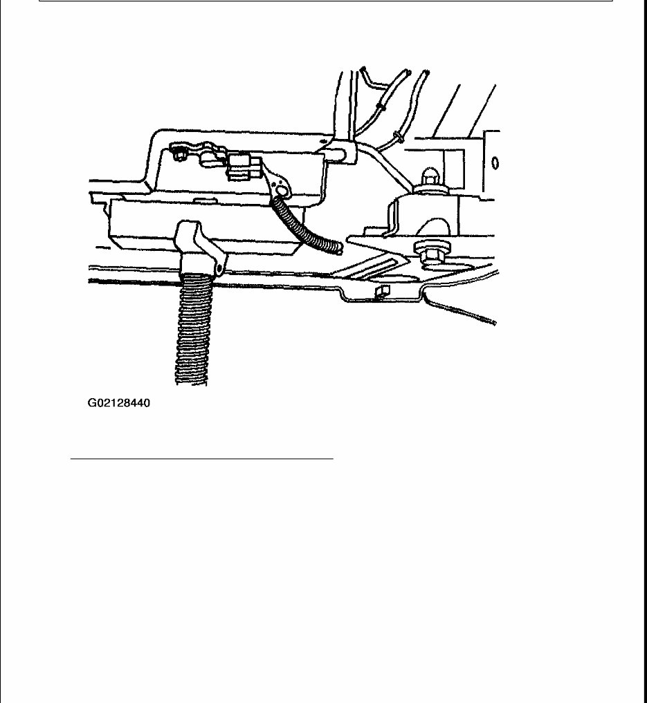
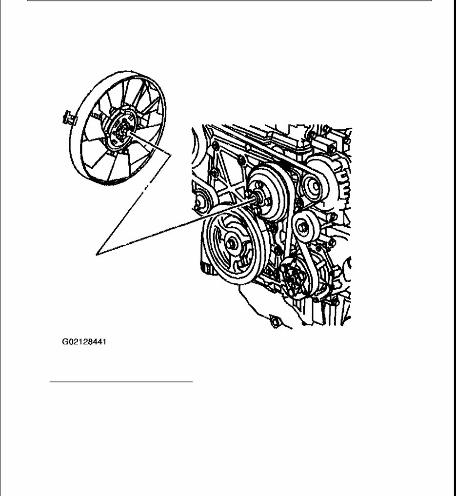
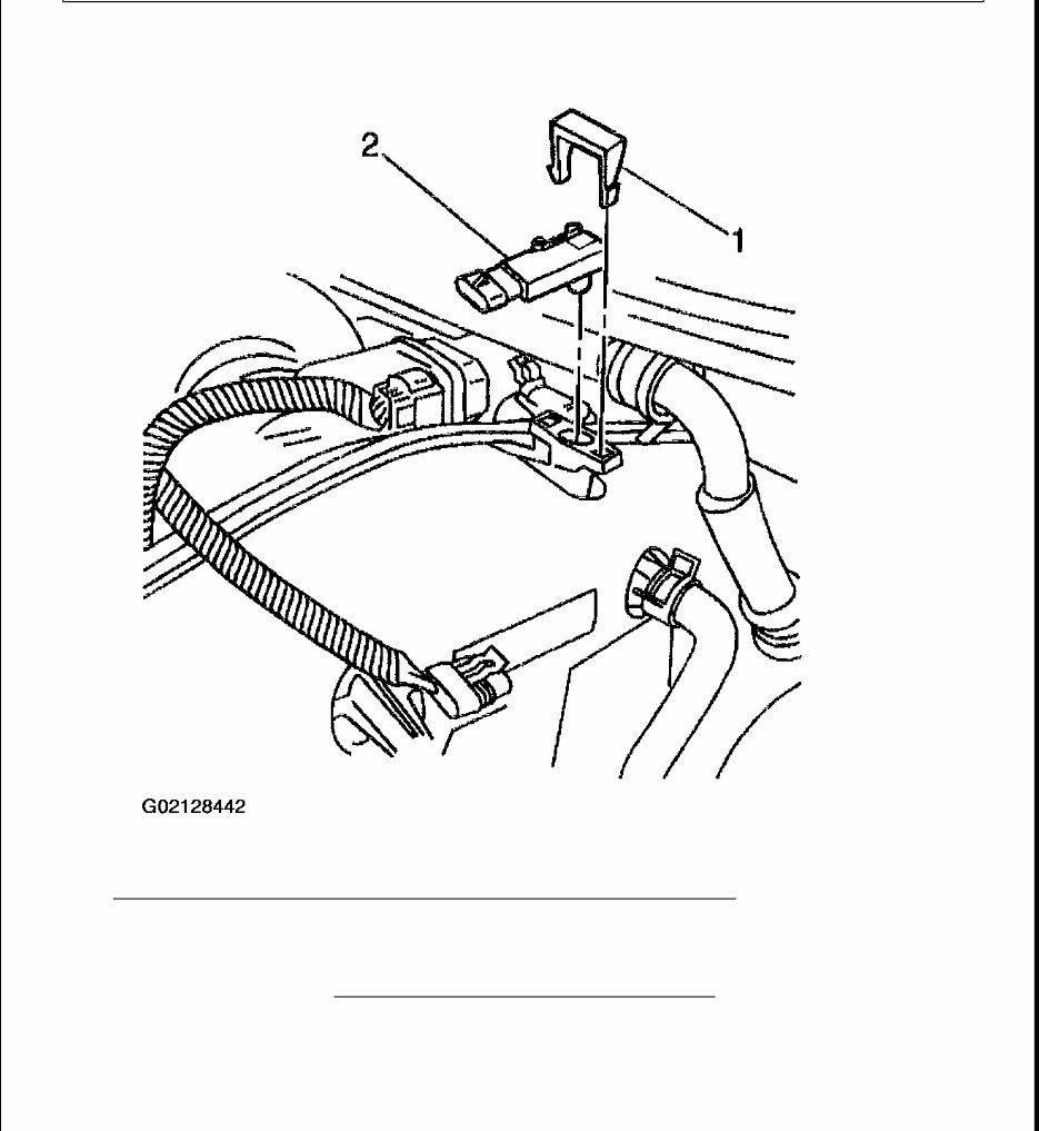
2. Remove the cooling fan. Refer to COOLING FAN AND SHROUD REPLACEMENT in Engine Cooling. Fig. 87: Removing Cooling Fan (Left) Courtesy of GENERAL MOTORS CORP. 3. Remove the MAP sensor electrical connector and the retainer (1). 4. Remove the MAP sensor (2). 5. Remove the left shock module (if frame mount is being removed). Refer to SHOCK MODULE REPLACEMENT in Front Suspension.
Fig. 88: Removing MAP Sensor, Electrical Connector & Retainer (Left) Courtesy of GENERAL MOTORS CORP. 6. Remove the right and the left upper engine mount nuts. 7. Raise the vehicle. Refer to LIFTING AND JACKING THE VEHICLE in General Information. 8. Remove the right and the left lower engine mount nuts.
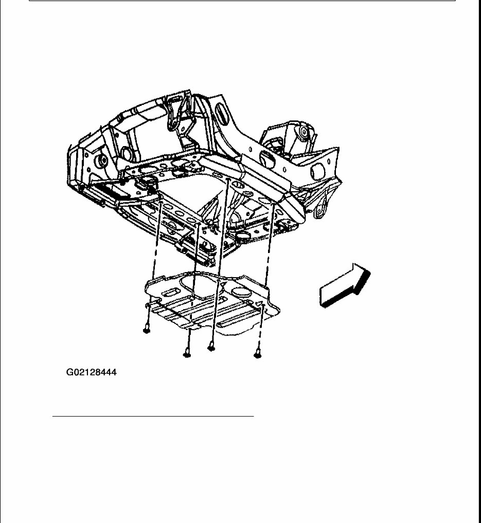
Fig. 89: Removing Right And Left Engine Mount Nuts (Left) Courtesy of GENERAL MOTORS CORP. 9. Remove the engine protection shield mount bolts. 10. Remove the engine protection shield. IMPORTANT: When placing jack onto the oil pan, pay close attention to not damage the oil level sender.
11. Lower the vehicle and place a floor jack under the oil pan with a block of wood. 12. Raise the engine with the jack just enough to clear the engine mount studs. Fig. 90: Removing Engine Protection Shield (Left) Courtesy of GENERAL MOTORS CORP. 13. Remove the left engine mount from the bracket.
This is a comprehensive service and repair manual designed for PC, MAC, tablets, and smartphones. It provides detailed instructions, wiring diagrams, and images to facilitate easy repair jobs, making it suitable for both professional mechanics and DIY enthusiasts. The manual covers all servicing and repair jobs, including routine maintenance.
Format: PDF
Language: English
Available: Yes
Compatible: Win/MAC/Linux
Instant delivery eliminates shipping costs and waiting time, allowing you to start repairs immediately upon payment receipt. The manual is user-friendly and can be accessed on PC, tablet, or laptop.
FAQ:
Why should I purchase this manual?
This manual features an easy-to-follow layout covering repair procedures in great detail, enhancing understanding of parts and repair processes. It empowers users to perform their own servicing, maintenance, and repairs.
What models are covered in this manual?
All models for the specified years and engine types are included.
What type of information is covered?
Each manual encompasses all aspects of service, repair, and maintenance.
How long for delivery?
Instant delivery upon payment via Credit/Debit/Paypal Account, eliminating shipping delays.
How much money will I save?
This manual can potentially save thousands of dollars by enabling DIY repairs, preventing overcharging by professionals for simple tasks.
Is this manual hard to use?
No, it is user-friendly and compatible with any PC/MAC computer.