

2017 Infiniti QX70 (S51) Service & Repair Manual (+ Wiring Diagrams)
What's Included?
Fast Download Speeds
Offline Viewing
Access Contents & Bookmarks
Full Search Facility
Print one or all pages of your manual

HAC-1
VENTILATION, HEATER & AIR CONDITIONER
C
D
E
F
G
H
J
K
L
M
SECTION HAC
A
B
HAC
N
O
P
CONTENTS
HEATER & AIR CONDITIONING CONTROL SYSTEM
AUTOMATIC AIR CONDITIONER
BASIC INSPECTION ................................... 4
DIAGNOSIS AND REPAIR WORKFLOW ......... 4
Work Flow ................................................................ 4
INSPECTION AND ADJUSTMENT .................... 7
WITHOUT ACCS ........................................................ 7
WITHOUT ACCS : Description & Inspection ............ 7
WITHOUT ACCS : Temperature Setting Trimmer ...... 8
WITHOUT ACCS : Foot Position Setting Trimmer ...... 9
WITHOUT ACCS : Inlet Port Memory Function ..... 10
WITH ACCS .............................................................. 10
WITH ACCS : Description & Inspection ................. 10
WITH ACCS : Temperature Setting Trimmer ......... 13
WITH ACCS : Foot Position Setting Trimmer ........ 14
WITH ACCS : Inlet Port Memory Function ............. 15
WITH ACCS : Exhaust exhaust gas/outside odor
detecting/Outside Odor Detecting Sensor Sensi-
tivity Adjustment Function ...................................... 15
WITH ACCS : Auto Intake Interlocking Movement
Change Function .................................................... 16
SYSTEM DESCRIPTION ............................ 17
COMPRESSOR CONTROL FUNCTION ...........17
WITHOUT ACCS ...................................................... 17
WITHOUT ACCS : Description .............................. 17
WITHOUT ACCS : Fail-safe ................................... 17
WITHOUT ACCS : Component Part Location ........ 18
WITHOUT ACCS : Component Description ........... 21
WITH ACCS .............................................................. 21
WITH ACCS : Description ...................................... 21
WITH ACCS : Fail-safe .......................................... 22
WITH ACCS : Component Part Location ............... 22
WITH ACCS : Component Description .................. 24
AUTOMATIC AIR CONDITIONER SYSTEM ....26
WITHOUT ACCS .......................................................26
WITHOUT ACCS : System Diagram ......................26
WITHOUT ACCS : System Description ..................26
WITHOUT ACCS : Component Part Location ........31
WITHOUT ACCS : Component Description ...........34
WITH ACCS ..............................................................34
WITH ACCS : System Diagram ..............................34
WITH ACCS : System Description .........................35
WITH ACCS : Component Part Location ................40
WITH ACCS : Component Description ...................42
PLASMACLUSTER SYSTEM ........................... 44
System Diagram .....................................................44
System Description .................................................44
Component Part Location .......................................45
Component Description ..........................................46
CAN COMMUNICATION SYSTEM ................... 47
System Description .................................................47
MODE DOOR CONTROL SYSTEM .................. 48
System Diagram .....................................................48
System Description .................................................48
AIR MIX DOOR CONTROL SYSTEM ............... 50
System Diagram .....................................................50
System Description .................................................50
INTAKE DOOR CONTROL SYSTEM ............... 52
WITHOUT ACCS .......................................................52
WITHOUT ACCS : System Diagram ......................52
WITHOUT ACCS : System Description ..................52
WITH ACCS ..............................................................53
WITH ACCS : System Diagram ..............................53
WITH ACCS : System Description .........................53
BLOWER MOTOR CONTROL SYSTEM .......... 55
System Diagram .....................................................55
System Description .................................................55
Revision: 2015 February 2015 QX70

HAC-2
MAGNET CLUTCH CONTROL SYSTEM ........ 57
System Diagram .................................................... 57
System Description ................................................ 57
DIAGNOSIS SYSTEM (UNIFIED METER & A/
C AMP.) ............................................................. 59
WITHOUT ACCS ...................................................... 59
WITHOUT ACCS : Diagnosis Description ............. 59
WITHOUT ACCS : CONSULT Function ................ 64
WITH ACCS ............................................................. 64
WITH ACCS : Diagnosis Description ..................... 64
WITH ACCS : CONSULT Function ........................ 69
DTC/CIRCUIT DIAGNOSIS ........................ 70
POWER SUPPLY AND GROUND CIRCUIT .... 70
UNIFIED METER AND A/C AMP. ............................ 70
UNIFIED METER AND A/C AMP. : Diagnosis Pro-
cedure .................................................................... 70
UNIFIED METER AND A/C AMP. .................... 71
Description ............................................................. 71
Component Function Check .................................. 71
Diagnosis Procedure ............................................. 71
MODE DOOR MOTOR ..................................... 72
Description ............................................................. 72
Component Function Check ................................ 72
Diagnosis Procedure ............................................. 72
AIR MIX DOOR MOTOR (DRIVER SIDE) ........ 74
Description ............................................................. 74
Component Function Check ................................ 74
Diagnosis Procedure ............................................. 74
AIR MIX DOOR MOTOR (PASSENGER SIDE)
... 76
Description ............................................................. 76
Component Function Check ................................ 76
Diagnosis Procedure ............................................. 76
INTAKE DOOR MOTOR ................................... 78
WITHOUT ACCS ...................................................... 78
WITHOUT ACCS : Description .............................. 78
WITHOUT ACCS : Component Function Check ... 78
WITHOUT ACCS : Diagnosis Procedure ............... 78
WITH ACCS ............................................................. 79
WITH ACCS : Description ..................................... 79
WITH ACCS : Component Function Check ......... 79
WITH ACCS : Diagnosis Procedure ...................... 80
BLOWER MOTOR ............................................ 82
Description ............................................................. 82
Component Function Check ................................ 82
Diagnosis Procedure ............................................. 82
Component Inspection ........................................... 85
MAGNET CLUTCH ........................................... 86
Description ............................................................. 86
Component Function Check .................................. 86
Diagnosis Procedure .............................................. 86
ECV (ELECTRICAL CONTROL VALVE) ......... 88
Description ............................................................. 88
Diagnosis Procedure .............................................. 88
AMBIENT SENSOR .......................................... 90
Description ............................................................. 90
Component Function Check ................................. 90
Diagnosis Procedure .............................................. 90
Component Inspection ........................................... 91
IN-VEHICLE SENSOR ...................................... 93
Description ............................................................. 93
Component Function Check ................................. 93
Diagnosis Procedure .............................................. 93
Component Inspection ........................................... 94
SUNLOAD SENSOR ........................................ 96
Description ............................................................. 96
Component Function Check ................................. 96
Diagnosis Procedure .............................................. 96
Component Inspection ........................................... 97
INTAKE SENSOR ............................................. 99
Description ............................................................. 99
Component Function Check ................................. 99
Diagnosis Procedure .............................................. 99
Component Inspection ......................................... 100
EXHAUST GAS/OUTSIDE ODOR DETECT-
ING SENSOR ................................................... 101
Description ........................................................... 101
Component Function Check ............................... 101
Diagnosis Procedure ............................................ 101
IONIZER ........................................................... 104
Description ........................................................... 104
Component Function Check ................................ 104
Diagnosis Procedure ............................................ 104
ECU DIAGNOSIS INFORMATION ............ 106
UNIFIED METER AND A/C AMP. ................... 106
Reference Value .................................................. 106
Wiring Diagram - AIR CONDITIONER CONTROL
SYSTEM - ............................................................ 108
Fail-safe ............................................................... 117
ECM ................................................................. 119
VQ37VHR FOR USA AND CANADA ..................... 119
VQ37VHR FOR USA AND CANADA : Reference
Value .................................................................... 119
VQ37VHR FOR MEXICO ....................................... 135
VQ37VHR FOR MEXICO : Reference Value ....... 135
VK50VE .................................................................. 150
VK50VE : Reference Value .................................. 150
Revision: 2015 February 2015 QX70

HAC-3
C
D
E
F
G
H
J
K
L
M
A
B
HAC
N
O
P
SYMPTOM DIAGNOSIS ........................... 169
AIR CONDITIONER CONTROL ...................... 169
Diagnosis Chart By Symptom .............................. 169
INSUFFICIENT COOLING .............................. 170
Description ........................................................... 170
Inspection procedure ............................................ 170
INSUFFICIENT HEATING ............................... 172
Description ........................................................... 172
Inspection procedure ............................................ 172
NOISE .............................................................. 174
Description ........................................................... 174
Inspection procedure ............................................ 174
SELF-DIAGNOSIS CANNOT BE PER-
FORMED ......................................................... 176
Description ........................................................... 176
Inspection procedure ............................................ 176
MEMORY FUNCTION DOES NOT OPERATE .. 177
Description ........................................................... 177
Inspection procedure ............................................ 177
PRECAUTION ........................................... 178
PRECAUTIONS ............................................... 178
Precaution for Supplemental Restraint System
(SRS) "AIR BAG" and "SEAT BELT PRE-TEN-
SIONER" .............................................................. 178
Precautions Necessary for Steering Wheel Rota-
tion After Battery Disconnection ........................... 178
Precaution for Procedure without Cowl Top Cover .. 179
Working with HFC-134a (R-134a) ........................ 179
General Refrigerant Precaution ........................... 179
Refrigerant Connection ........................................ 180
Service Equipment ............................................... 184
COMPRESSOR ............................................... 187
VQ37VHR ............................................................... 187
VQ37VHR : General Precautions ......................... 187
VK50VE .................................................................. 187
VK50VE : General Precautions ............................ 187
LEAK DETECTION DYE ................................. 188
General Precautions ............................................ 188
PREPARATION ........................................ 189
PREPARATION ............................................... 189
Special Service Tool ............................................ 189
Commercial Service Tool ..................................... 192
Sealant or/and Lubricant ...................................... 192
REMOVAL AND INSTALLATION ............ 193
PRESET SWITCH ........................................... 193
Exploded View ...................................................... 193
Removal and Installation ...................................... 193
UNIFIED METER AND A/C AMP. ................... 194
Exploded View ...................................................... 194
Removal and Installation ...................................... 194
AMBIENT SENSOR ........................................ 195
Exploded View ...................................................... 195
Removal and Installation ...................................... 195
IN-VEHICLE SENSOR .................................... 196
Exploded View ...................................................... 196
Removal and Installation ...................................... 196
SUNLOAD SENSOR ....................................... 197
Exploded View ...................................................... 197
Removal and Installation ...................................... 197
INTAKE SENSOR ........................................... 198
Exploded View ...................................................... 198
Removal and Installation ...................................... 199
EXHAUST GAS/OUTSIDE ODOR DETECT-
ING SENSOR .................................................. 200
Exploded View ...................................................... 200
Removal and Installation ...................................... 200
REFRIGERANT PRESSURE SENSOR .......... 201
Exploded View ...................................................... 201
Removal and Installation ...................................... 201
DOOR MOTOR ................................................ 202
Exploded View ...................................................... 202
MODE DOOR MOTOR ............................................ 202
MODE DOOR MOTOR : Removal and Installation .. 202
AIR MIX DOOR MOTOR ......................................... 203
AIR MIX DOOR MOTOR : Removal and Installa-
tion ........................................................................ 203
INTAKE DOOR MOTOR ......................................... 204
INTAKE DOOR MOTOR : Removal and Installa-
tion ........................................................................ 204
IONIZER .......................................................... 205
Exploded View ...................................................... 205
Removal and Installation ...................................... 205
Revision: 2015 February 2015 QX70
HAC-4
< BASIC INSPECTION >
[AUTOMATIC AIR CONDITIONER]
DIAGNOSIS AND REPAIR WORKFLOW
BASIC INSPECTION
DIAGNOSIS AND REPAIR WORKFLOW
Work Flow INFOID:0000000010581326
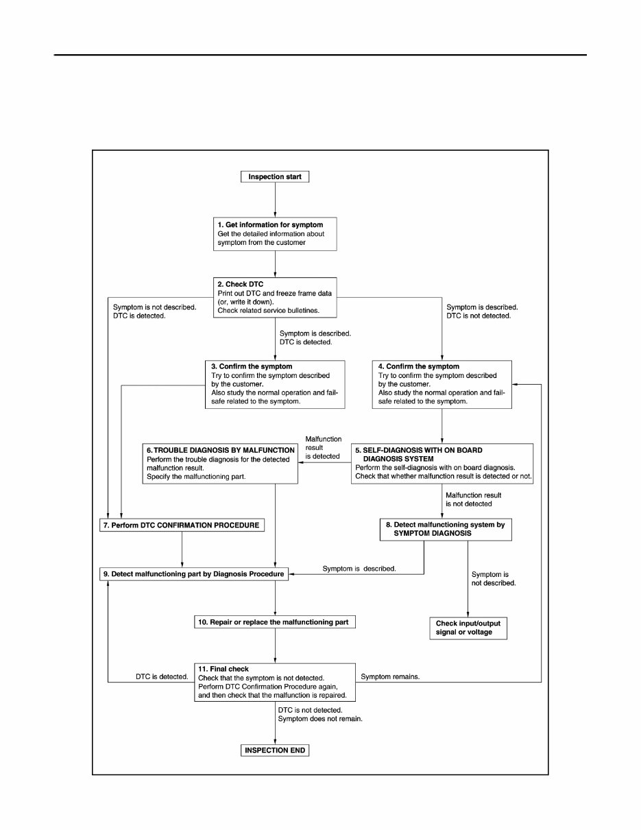
OVERALL SEQUENCE
DETAILED FLOW
JMIIA2097GB
Revision: 2015 February 2015 QX70

DIAGNOSIS AND REPAIR WORKFLOW
HAC-5
< BASIC INSPECTION >
[AUTOMATIC AIR CONDITIONER]
C
D
E
F
G
H
J
K
L
M
A
B
HAC
N
O
P
1.GET INFORMATION FOR SYMPTOM
1. Get detailed information from the customer about the symptom (the condition and the environment when
the incident/malfunction occurs).
2. Check operation condition of the function that is malfunctioning.
>> GO TO 2.
2.CHECK DTC
1. Check DTC.
2. Perform the following procedure if DTC is detected.
- Record DTC and freeze frame data (Print them out using CONSULT.)
- Erase DTC.
- Study the relationship between the cause detected by DTC and the symptom described by the customer.
3. Check related service bulletins for information.
Are any symptoms described and any DTC detected?
Symptom is described, DTC is detected>>GO TO 3.
Symptom is described, DTC is not detected>>GO TO 4.
Symptom is not described, DTC is detected>>GO TO 7.
3.CONFIRM THE SYMPTOM
Try to confirm the symptom described by the customer.
Also study the normal operation and fail-safe related to the symptom.
Verify relation between the symptom and the condition when the symptom is detected.
>> GO TO 7.
4.CONFIRM THE SYMPTOM
Try to confirm the symptom described by the customer.
Also study the normal operation and fail-safe related to the symptom.
Verify relation between the symptom and the condition when the symptom is detected.
>> GO TO 5.
5.SELF-DIAGNOSIS WITH ON BOARD DIAGNOSIS SYSTEM
Perform the self-diagnosis with on board diagnosis. Check that whether malfunction result is detected or not.
Is malfunction result detected?
YES >> GO TO 6.
NO >> GO TO 8.
6.TROUBLE DIAGNOSIS BY MALFUNCTION
Perform the trouble diagnosis for the detected malfunction result. Specify the malfunctioning part.
>> GO TO 9.
7.PERFORM DTC CONFIRMATION PROCEDURE
Perform DTC CONFIRMATION PROCEDURE for the detected DTC, and then check that DTC is detected
again. At this time, always connect CONSULT to the vehicle, and check self diagnostic results in real time.
If two or more DTCs are detected, refer to DTC INSPECTION PRIORITY CHART, and determine trouble diag-
nosis order.
NOTE:
• Freeze frame data is useful if the DTC is not detected.
• Perform Component Function Check if DTC CONFIRMATION PROCEDURE is not included on Service
Manual. This simplified check procedure is an effective alternative though DTC cannot be detected during
this check.
If the result of Component Function Check is NG, it is the same as the detection of DTC by DTC CONFIR-
MATION PROCEDURE.
Is DTC detected?
Revision: 2015 February 2015 QX70

HAC-6
< BASIC INSPECTION >
[AUTOMATIC AIR CONDITIONER]
DIAGNOSIS AND REPAIR WORKFLOW
YES >> GO TO 9.
NO >> Check according to GI-47, " Intermittent Incident " .
8.DETECT MALFUNCTIONING SYSTEM BY SYMPTOM DIAGNOSIS
Detect malfunctioning system according to SYMPTOM DIAGNOSIS based on the confirmed symptom in step
4, and determine the trouble diagnosis order based on possible causes and symptom.
Is the symptom described?
YES >> GO TO 9.
NO >> Monitor input data from related sensors or check voltage of related module terminals using CON-
SULT.
9.DETECT MALFUNCTIONING PART BY DIAGNOSIS PROCEDURE
Inspect according to Diagnosis Procedure of the system.
Is malfunctioning part detected?
YES >> GO TO 10.
NO >> Check according to GI-47, " Intermittent Incident " .
10.REPAIR OR REPLACE THE MALFUNCTIONING PART
1. Repair or replace the malfunctioning part.
2. Reconnect parts or connectors disconnected during Diagnosis Procedure again after repair and replace-
ment.
3. Check DTC. If DTC is detected, erase it.
>> GO TO 11.
11.FINAL CHECK
When DTC is detected in step 2, perform DTC CONFIRMATION PROCEDURE again, and then check that the
malfunction is repaired securely.
When symptom is described by the customer, refer to confirmed symptom in step 3 or 4, and check that the
symptom is not detected.
Is DTC detected and does symptom remain?
YES-1 >> DTC is detected: GO TO 9.
YES-2 >> Symptom remains: GO TO 4.
NO >> Before returning the vehicle to the customer, always erase DTC.
Revision: 2015 February 2015 QX70
INSPECTION AND ADJUSTMENT
HAC-7
< BASIC INSPECTION >
[AUTOMATIC AIR CONDITIONER]
C
D
E
F
G
H
J
K
L
M
A
B
HAC
N
O
P
INSPECTION AND ADJUSTMENT
WITHOUT ACCS
WITHOUT ACCS : Description & Inspection INFOID:0000000010581327
DESCRIPTION
The purpose of the operational check is to check that the individual system operates normally.
INSPECTION PROCEDURE
1.CHECK MEMORY FUNCTION
1. Start the engine.
2. Turn temperature control dial (driver side) clockwise until 32.0°C (90°F) is displayed.
3. Press the OFF switch.
4. Turn the ignition switch OFF.
5. Turn the ignition switch ON.
6. Press the AUTO switch.
7. Check that the temperature setting before turning the ignition switch OFF is stored.
Is the inspection result normal?
YES >> GO TO 2.
NO >> Memory function malfunction: HAC-177, " Inspection procedure " .
2.CHECK BLOWER MOTOR SPEED
1. Start the engine.
2. Press fan (UP: +) switch. Check that the fan speed changes. Check the operation for all fan speeds.
3. Set the fan speed to max speed.
Is the inspection result normal?
YES >> GO TO 3.
NO >> Blower motor system malfunction: HAC-82, " Diagnosis Procedure " .
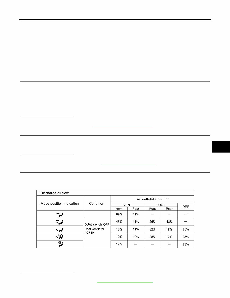
3.CHECK DISCHARGE AIR
1. Press the MODE switch and the DEF switch.
2. Each position indicator should change shape.
3. Confirm that discharge air comes out according to the air distribution table as follows:
NOTE:
Confirm that the compressor clutch is engaged (sound or visual inspection) and the intake door position is at
FRE when D/F or DEF is selected.
Is the inspection result normal?
YES >> GO TO 4.
NO >> Mode door system malfunction: HAC-72, " Diagnosis Procedure " .
Conditions : Engine running at normal operating temperature
JSIIA1208GB
Revision: 2015 February 2015 QX70

HAC-8
< BASIC INSPECTION >
[AUTOMATIC AIR CONDITIONER]
INSPECTION AND ADJUSTMENT
4.CHECK INTAKE AIR
1. Press intake switch. REC indicator turns ON.
2. Press intake switch again. FRE indicator turns ON.
3. Listen for intake door position change. (Slight change of blower sound can be heard.)
NOTE:
Confirm that the compressor clutch is engaged (sound or visual inspection) and the intake door position is at
FRE when D/F or DEF is selected.
Is the inspection result normal?
YES >> GO TO 5.
NO >> Intake door system malfunction: HAC-78, " WITHOUT ACCS : Diagnosis Procedure " .
5.CHECK A/C SWITCH
1. Press the A/C switch.
2. A/C switch indicator turns ON.
Confirm that the compressor clutch engages (sound or visual inspection).
Is the inspection result normal?
YES >> GO TO 6.
NO >> Magnet clutch system malfunction: HAC-86, " Diagnosis Procedure " .
6.CHECK WITH TEMPERATURE SETTING LOWERED
1. Turn temperature control dial (driver side) counterclockwise until 18.0°C (60°F) is displayed.
2. Check that the cool air blows from the outlets.
Is the inspection result normal?
YES >> GO TO 7.
NO >> Insufficient cooling: HAC-170, " Inspection procedure " .
7.CHECK WITH TEMPERATURE SETTING RAISED
1. Turn temperature control dial (driver side) clockwise until 32.0°C (90°F) is displayed.
2. Check that the warm air blows from the outlets.
Is the inspection result normal?
YES >> GO TO 8.
NO >> Insufficient heating: HAC-172, " Inspection procedure " .
8.CHECK LEFT AND RIGHT VENTILATION TEMPERATURE SEPARATELY CONTROL SYSTEM FUNC-
TION
1. Press the DUAL switch, and then check that “DUAL” is shown on the display.
2. Operate temperature control dial (driver side). Check that the discharge air temperature (driver side)
changes.
3. Operate the temperature control dial (passenger side). Check that the discharge air temperature (passen-
ger side) changes.
4. Press the DUAL switch, and then check that the temperature setting (LH/RH) is unified to the driver side
temperature setting.
Is the inspection result normal?
YES >> GO TO 9.
NO >> Refer to HAC-169, " Diagnosis Chart By Symptom " and perform the appropriate diagnosis.
9.CHECK AUTO MODE
1. Press the AUTO switch, and then check that “AUTO” is shown on the display.
2. Check that the discharge air and blower speed depend on ambient temperature, in-vehicle temperature
and temperature setting.
Is the inspection result normal?
YES >> INSPECTION END
NO >> Refer to HAC-169, " Diagnosis Chart By Symptom " and perform the appropriate diagnosis.
WITHOUT ACCS : Temperature Setting Trimmer INFOID:0000000010581328
DESCRIPTION
Revision: 2015 February 2015 QX70
INSPECTION AND ADJUSTMENT
HAC-9
< BASIC INSPECTION >
[AUTOMATIC AIR CONDITIONER]
C
D
E
F
G
H
J
K
L
M
A
B
HAC
N
O
P
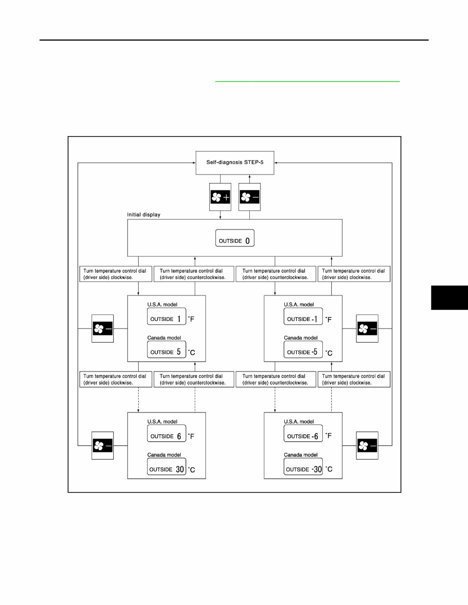
The trimmer compensates for differences in range of ±3°C (±6°F) between temperature setting (displayed dig-
itally) and temperature felt by customer.
Operating procedures for this trimmer are as per the following:
1. Begin self-diagnosis STEP-5 mode. Refer to HAC-59, " WITHOUT ACCS : Diagnosis Description " .
2. Press fan (UP: +) switch to set system in auxiliary mode.
3. Display shows “61” in auxiliary mechanism. It takes approximately 3 seconds to enable setting operation.
4. Turn temperature control dial (driver side) as desired. Temperature will change at a rate of 0.5°C (1.0°F)
each time a dial is turned.
CAUTION:
A decimal point is not indicated on the display.
NOTE:
When battery cable is disconnected or battery voltage is below 10 V, trimmer operation is canceled. Tempera-
ture set becomes that of initial condition.
WITHOUT ACCS : Foot Position Setting Trimmer INFOID:0000000010581329
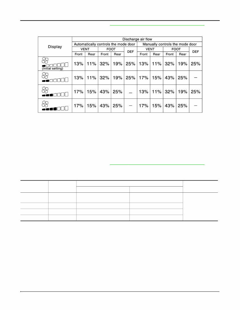
DESCRIPTION
Wind distribution ratio in FOOT mode can be set.
Operating procedures for this trimmer are as per the following:
JSIIA1210GB
Revision: 2015 February 2015 QX70
HAC-10
< BASIC INSPECTION >
[AUTOMATIC AIR CONDITIONER]
INSPECTION AND ADJUSTMENT
1. Begin self-diagnosis STEP-5 mode. Refer to HAC-59, " WITHOUT ACCS : Diagnosis Description " .
2. Press fan (UP: +) switch to set system in auxiliary mode.
3. Press mode switch as desired.
NOTE:
When battery cable is disconnected or battery voltage is below 10 V, trimmer operation is canceled. Air distri-
bution ratio set becomes that of initial condition.
WITHOUT ACCS : Inlet Port Memory Function INFOID:0000000010581330
DESCRIPTION
When ignition switch is turned from OFF to ON, inlet port can be set to AUTO or manual.
Operating procedures for this trimmer are as per the following:
1. Begin self-diagnosis STEP-5 mode. Refer to HAC-59, " WITHOUT ACCS : Diagnosis Description " .
2. Press fan (UP: +) switch to set system in auxiliary mode.
3. Press intake switch as desired.
NOTE:
When battery cable is disconnected or battery voltage is below 10 V, memory function is canceled. Memory
function set becomes that of initial condition.
WITH ACCS
WITH ACCS : Description & Inspection INFOID:0000000010581331
DESCRIPTION
The purpose of the operational check is to check that the individual system operates normally.
INSPECTION PROCEDURE
1.CHECK MEMORY FUNCTION
1. Start the engine.
JSIIA1209GB
FRE indicator REC indicator
Setting status
Setting changeover
method
FRE REC
OFF ON AUTO control (Initial setting)
Manual REC status is memorized.
(Initial setting)
Intake switch: ON
ON ON Manual FRE status is memorized. Manual REC status is memorized.
ON OFF Manual FRE status is memorized. AUTO control
OFF OFF AUTO control AUTO control
Conditions : Engine running at normal operating temperature
Revision: 2015 February 2015 QX70
You're Reading a Preview
What's Included?
Fast Download Speeds
Offline Viewing
Access Contents & Bookmarks
Full Search Facility
Print one or all pages of your manual
$35.99
Viewed 55 Times Today


Secure transaction
What's Included?
Fast Download Speeds
Offline Viewing
Access Contents & Bookmarks
Full Search Facility
Print one or all pages of your manual
$35.99
- The 2017 Infiniti QX70 (S51) Service & Repair Manual (+ Wiring Diagrams) is a comprehensive resource for fixing vehicle issues using a Do-It-Yourself approach.
- It includes troubleshooting and replacement procedures recommended by the manufacturer, along with step-by-step instructions, clear images, and exploded-view illustrations.
- Regular maintenance is essential for the vehicle's durability, and this manual provides the manufacturer's recommended troubleshooting charts and replacement procedures.
- By using this manual, you can save on repairs, enhance your vehicle's reliability, and reduce visits to the repair shop.
- It offers easy access to specific information without the hassle of flipping through numerous pages, making it more convenient than traditional bound manuals.
- The manual is available in a printable format and is compatible with various electronic devices, including PC & Mac computers, Android and Apple smartphones & tablets, etc.
- It requires Adobe Reader, which is available for free.


