

2017 Infiniti QX60 (L50) Service & Repair Manual (+ Wiring Diagrams)
What's Included?
Fast Download Speeds
Offline Viewing
Access Contents & Bookmarks
Full Search Facility
Print one or all pages of your manual

ACC-1
ENGINE
C
D
E
F
G
H
I
J
K
L
M
SECTION ACC
A
ACC
N
O
P
CONTENTS
ACCELERATOR CONTROL SYSTEM
PRECAUTION .............................................. 2
PRECAUTIONS .................................................. 2
Precaution for Supplemental Restraint System
(SRS) "AIR BAG" and "SEAT BELT PRE-TEN-
SIONER" .................................................................. 2
REMOVAL AND INSTALLATION ............... 3
ACCELERATOR CONTROL SYSTEM .............. 3
MODELS WITHOUT DISTANCE CONTROL AS-
SIST SYSTEM ............................................................ 3
MODELS WITHOUT DISTANCE CONTROL AS-
SIST SYSTEM : Exploded View ............................... 3
MODELS WITHOUT DISTANCE CONTROL AS-
SIST SYSTEM : Removal and Installation ............... 3
MODELS WITHOUT DISTANCE CONTROL AS-
SIST SYSTEM : Inspection ..................................... 4
MODELS WITH DISTANCE CONTROL ASSIST
SYSTEM ..................................................................... 4
MODELS WITH DISTANCE CONTROL ASSIST
SYSTEM : Exploded View ....................................... 5
MODELS WITH DISTANCE CONTROL ASSIST
SYSTEM : Removal and Installation ....................... 5
MODELS WITH DISTANCE CONTROL ASSIST
SYSTEM : Inspection .............................................. 5
SERVICE DATA AND SPECIFICATIONS
(SDS) ............................................................ 7
SERVICE DATA AND SPECIFICATIONS
(SDS) .................................................................. 7
Accelerator Control .................................................. 7
Revision: August 2016 2017 QX60 NAM

ACC-2
< PRECAUTION >
PRECAUTIONS
PRECAUTION
PRECAUTIONS
Precaution for Supplemental Restraint System (SRS) "AIR BAG" and "SEAT BELT
PRE-TENSIONER" INFOID:0000000014448734
The Supplemental Restraint System such as “AIR BAG” and “SEAT BELT PRE-TENSIONER”, used along
with a front seat belt, helps to reduce the risk or severity of injury to the driver and front passenger for certain
types of collision. This system includes dual stage front air bag modules. The SRS system may only deploy
one front air bag, depending on the severity of a collision and whether the front passenger seat is occupied.
Information necessary to service the system safely is included in the SR and SB section of this Service Man-
ual.
WARNING:
• To avoid rendering the SRS inoperative, which could increase the risk of personal injury or death in
the event of a collision which would result in air bag inflation, it is recommended that all mainte-
nance and repair be performed by an authorized NISSAN/INFINITI dealer.
• Improper repair, including incorrect removal and installation of the SRS, can lead to personal injury
caused by unintentional activation of the system. For removal of Spiral Cable and Air Bag Module,
see the SR section.
• Do not use electrical test equipment on any circuit related to the SRS unless instructed to in this
Service Manual. SRS wiring harnesses can be identified by yellow and/or orange harnesses or har-
ness connectors.
PRECAUTIONS WHEN USING POWER TOOLS (AIR OR ELECTRIC) AND HAMMERS
WARNING:
• When working near the Air Bag Diagnosis Sensor Unit or other Air Bag System sensors with the
Ignition ON or engine running, DO NOT use air or electric power tools or strike near the sensor(s)
with a hammer. Heavy vibration could activate the sensor(s) and deploy the air bag(s), possibly
causing serious injury.
• When using air or electric power tools or hammers, always switch the Ignition OFF, disconnect the
battery or batteries, and wait at least three minutes before performing any service.
Revision: August 2016 2017 QX60 NAM
ACCELERATOR CONTROL SYSTEM
ACC-3
< REMOVAL AND INSTALLATION >
C
D
E
F
G
H
I
J
K
L
M
A
ACC
N
P
O
REMOVAL AND INSTALLATION
ACCELERATOR CONTROL SYSTEM
MODELS WITHOUT DISTANCE CONTROL ASSIST SYSTEM
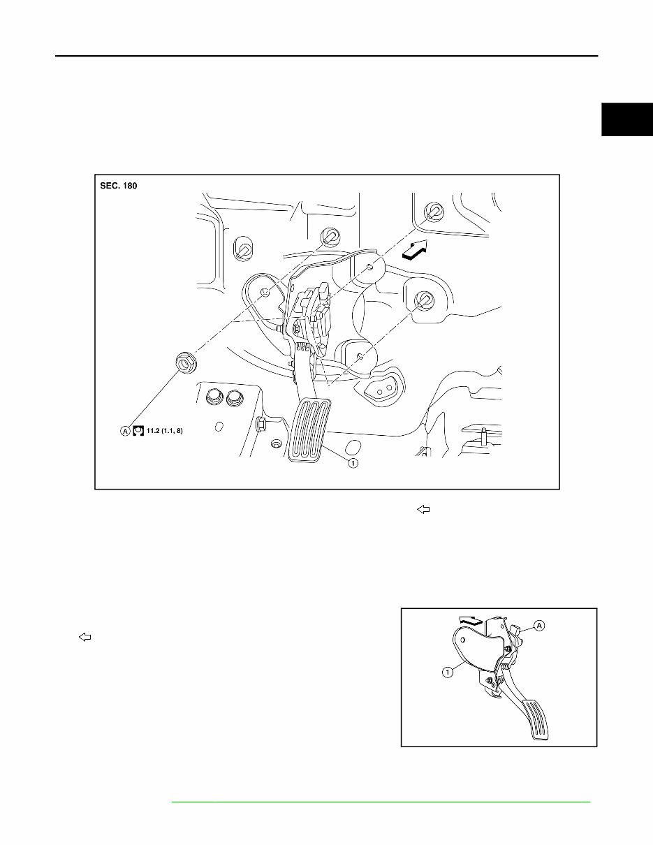
MODELS WITHOUT DISTANCE CONTROL ASSIST SYSTEM : Exploded View
INFOID:0000000014448735
MODELS WITHOUT DISTANCE CONTROL ASSIST SYSTEM : Removal and Instal-
lation INFOID:0000000014448736
REMOVAL
1. Remove three accelerator pedal assembly nuts.
2. Disconnect harness connector (A) from the accelerator pedal
assembly (1).
: Front
3. Remove the accelerator pedal assembly from vehicle.
CAUTION:
• Do not disassemble accelerator pedal assembly.
• Do not drop or impact accelerator pedal assembly.
• Do not expose accelerator pedal assembly to water.
INSTALLATION
Installation is in the reverse order of removal.
NOTE:
For inspection, refer to ACC-4, " MODELS WITHOUT DISTANCE CONTROL ASSIST SYSTEM : Inspection " .
1.
Accelerator pedal assembly
A. Nut
Front
ALBIA0775GB
ALBIA0776GB
Revision: August 2016 2017 QX60 NAM
ACC-4
< REMOVAL AND INSTALLATION >
ACCELERATOR CONTROL SYSTEM
MODELS WITHOUT DISTANCE CONTROL ASSIST SYSTEM : Inspection
INFOID:0000000014448737
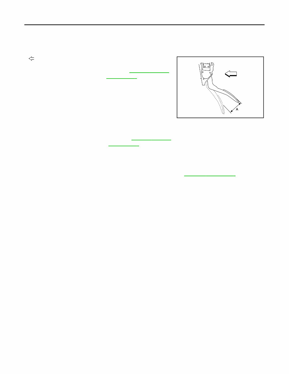
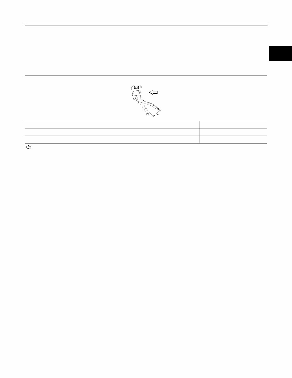
INSPECTION AFTER INSTALLATION
• Check that the accelerator pedal moves smoothly within the specified range.
: Front
• Check the accelerator pedal height.
• Depress and release the accelerator pedal to check that it returns quickly and smoothly to the original
released position.
CAUTION:
• Whenever the harness connector of the accelerator pedal position sensor has been disconnected,
perform "Accelerator Pedal Released Position Learning". Refer to EC-895, " Description " .
• The accelerator pedal should operate smoothly without catching when the pedal operating force is
released. The pedal should return smoothly to the fully raised position. The spring should be free
from damage.
MODELS WITH DISTANCE CONTROL ASSIST SYSTEM
Accelerator pedal stroke
(A)
: Refer to ACC-7, " Acceler-
ator Control "
ALBIA0798ZZ
Accelerator pedal height : Refer to ACC-7, " Acceler-
ator Control "
Revision: August 2016 2017 QX60 NAM
ACCELERATOR CONTROL SYSTEM
ACC-5
< REMOVAL AND INSTALLATION >
C
D
E
F
G
H
I
J
K
L
M
A
ACC
N
P
O
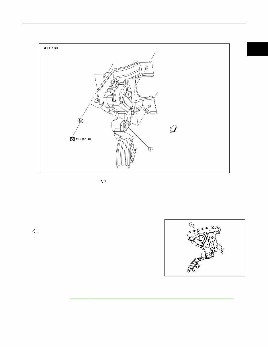
MODELS WITH DISTANCE CONTROL ASSIST SYSTEM : Exploded View
INFOID:0000000014448738
MODELS WITH DISTANCE CONTROL ASSIST SYSTEM : Removal and Installation
INFOID:0000000014448739
REMOVAL
1. Remove three accelerator pedal assembly nuts.
2. Disconnect the harness connector (A) from the accelerator
pedal assembly.
: Front
3. Remove the accelerator pedal assembly from vehicle.
CAUTION:
• Do not disassemble accelerator pedal assembly.
• Do not drop or impact accelerator pedal assembly.
• Do not expose accelerator pedal assembly to water.
INSTALLATION
Installation is in the reverse order of removal.
NOTE:
For inspection, refer to ACC-5, " MODELS WITH DISTANCE CONTROL ASSIST SYSTEM : Inspection " .
MODELS WITH DISTANCE CONTROL ASSIST SYSTEM : Inspection INFOID:0000000014448740
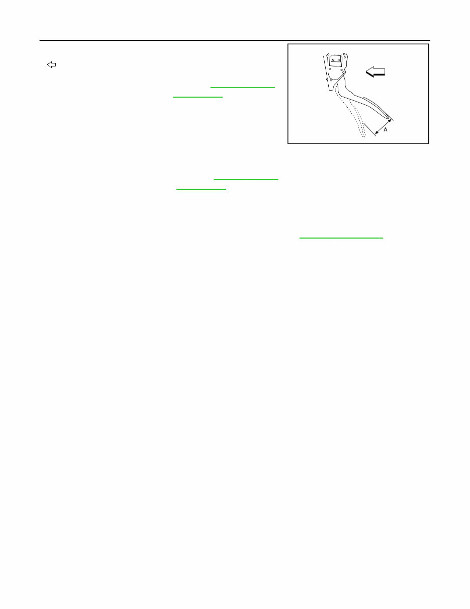
INSPECTION AFTER INSTALLATION
1.
Accelerator pedal assembly
Front
ALBIA1273ZZ
ALBIA1275ZZ
Revision: August 2016 2017 QX60 NAM
ACC-6
< REMOVAL AND INSTALLATION >
ACCELERATOR CONTROL SYSTEM
• Check that the accelerator pedal moves smoothly within the speci-
fied range.
: Front
• Check the accelerator pedal height.
• Depress and release the accelerator pedal to check that it returns quickly and smoothly to the original
released position.
CAUTION:
• Whenever the harness connector of the accelerator pedal position sensor has been disconnected,
perform "Accelerator Pedal Released Position Learning". Refer to EC-895, " Description " .
• The accelerator pedal should operate smoothly without catching when the pedal operating force is
released. The pedal should return smoothly to the fully raised position. The spring should be free
from damage.
Accelerator pedal stroke
(A)
: Refer to ACC-7, " Acceler-
ator Control "
ALBIA0798ZZ
Accelerator pedal height : Refer to ACC-7, " Acceler-
ator Control "
Revision: August 2016 2017 QX60 NAM
SERVICE DATA AND SPECIFICATIONS (SDS)
ACC-7
< SERVICE DATA AND SPECIFICATIONS (SDS)
C
D
E
F
G
H
I
J
K
L
M
A
ACC
N
P
O
SERVICE DATA AND SPECIFICATIONS (SDS)
SERVICE DATA AND SPECIFICATIONS (SDS)
Accelerator Control INFOID:0000000014448741
MODELS WITH AND WITHOUT DISTANCE CONTROL ASSIST ACCELERATOR PEDAL
Unit: mm (in)
: Front
Models without distance control assist accelerator pedal stroke (A) 50.5 - 53.5 (1.99 - 2.11)
Models with distance control assist accelerator pedal stroke (A) 48.5 - 51.5 (1.91 - 2.03)
Accelerator pedal height 164.2 - 174.2 (6.46 - 6.86)
ALBIA0798ZZ
Revision: August 2016 2017 QX60 NAM
You're Reading a Preview
What's Included?
Fast Download Speeds
Offline Viewing
Access Contents & Bookmarks
Full Search Facility
Print one or all pages of your manual
$35.99
Viewed 27 Times Today


Secure transaction
What's Included?
Fast Download Speeds
Offline Viewing
Access Contents & Bookmarks
Full Search Facility
Print one or all pages of your manual
$35.99
- This service and repair manual for the 2017 Infiniti QX60 (L50) provides comprehensive troubleshooting and replacement procedures recommended by the manufacturer.
- It includes step-by-step instructions, clear images, and exploded-view illustrations, making it useful for both professional mechanics and DIY enthusiasts.
- Regular maintenance is essential for the durability of your vehicle, and this manual equips you with the necessary information to address wear and tear on various parts.
- With the manufacturer's recommended troubleshooting charts and replacement procedures, this manual enables you to save on repairs, enhance your vehicle's reliability, and reduce reliance on repair shops.
- Conveniently accessible and searchable, this digital manual eliminates the hassle of flipping through numerous pages and offers a practical alternative to traditional bound manuals.
- It is compatible with various electronic devices, including PC and Mac computers, Android and Apple smartphones, and tablets, and can be printed for physical reference.
- Language: English
- Requirements: Adobe Reader (free)


