HAC-1 VENTILATION, HEATER & AIR CONDITIONER C D E F G H J K L M SECTION HAC A B HAC N O P CONTENTS HEATER & AIR CONDITIONING CONTROL SYSTEM AUTOMATIC AIR CONDITIONING PRECAUTION .............................................. 5 PRECAUTIONS .................................................. 5 Precaution for Supplemental Restraint System (SRS) "AIR BAG" and "SEAT BELT PRE-TEN- SIONER" .................................................................. 5 SYSTEM DESCRIPTION ............................. 6 COMPONENT PARTS ....................................... 6 FRONT AUTOMATIC AIR CONDITIONING SYS- TEM ............................................................................. 6 FRONT AUTOMATIC AIR CONDITIONING SYS- TEM : Component Parts Location ............................ 6 FRONT AUTOMATIC AIR CONDITIONING SYS- TEM : Component Description ................................. 7 REAR AUTOMATIC AIR CONDITIONING SYS- TEM ............................................................................. 8 REAR AUTOMATIC AIR CONDITIONING SYS- TEM : Component Parts Location ............................ 9 REAR AUTOMATIC AIR CONDITIONING SYS- TEM : Component Description ............................... 10 ACCS (ADVANCED CLIMATE CONTROL SYS- TEM) ......................................................................... 10 ACCS (ADVANCED CLIMATE CONTROL SYS- TEM) : Component Parts Location ......................... 11 ACCS (ADVANCED CLIMATE CONTROL SYS- TEM) : Component Description .............................. 11 Aspirator ................................................................. 12 Front Blower Motor ................................................. 12 Rear Blower Motor ................................................. 13 Refrigerant Pressure Sensor .................................. 13 SYSTEM ............................................................14 FRONT AUTOMATIC AIR CONDITIONING SYS- TEM ........................................................................... 14 FRONT AUTOMATIC AIR CONDITIONING SYS- TEM : System Diagram ..........................................14 FRONT AUTOMATIC AIR CONDITIONING SYS- TEM : System Description ......................................14 FRONT AUTOMATIC AIR CONDITIONING SYS- TEM : Air Flow Control ...........................................15 FRONT AUTOMATIC AIR CONDITIONING SYS- TEM : Air Inlet Control ............................................16 FRONT AUTOMATIC AIR CONDITIONING SYS- TEM : Air Outlet Control .........................................17 FRONT AUTOMATIC AIR CONDITIONING SYS- TEM : Compressor Control .....................................17 FRONT AUTOMATIC AIR CONDITIONING SYS- TEM : Door Control .................................................18 FRONT AUTOMATIC AIR CONDITIONING SYS- TEM : Temperature Control ....................................21 FRONT AUTOMATIC AIR CONDITIONING SYS- TEM : Fail-safe .......................................................21 REAR AUTOMATIC AIR CONDITIONING SYS- TEM ...........................................................................22 REAR AUTOMATIC AIR CONDITIONING SYS- TEM : System Diagram ..........................................23 REAR AUTOMATIC AIR CONDITIONING SYS- TEM : System Description ......................................23 REAR AUTOMATIC AIR CONDITIONING SYS- TEM : Air Flow Control ...........................................24 REAR AUTOMATIC AIR CONDITIONING SYS- TEM : Air Outlet Control .........................................25 REAR AUTOMATIC AIR CONDITIONING SYS- TEM : Door Control .................................................26 REAR AUTOMATIC AIR CONDITIONING SYS- TEM : Temperature Control ....................................27 ACCS (ADVANCED CLIMATE CONTROL SYS- TEM) ..........................................................................27 ACCS (ADVANCED CLIMATE CONTROL SYS- TEM) : System Diagram .........................................28 ACCS (ADVANCED CLIMATE CONTROL SYS- TEM) : System Description .....................................28 Revision: 2010 May 2011 QX56
HAC-2 ACCS (ADVANCED CLIMATE CONTROL SYS- TEM) : Automatic Intake Control (Exhaust Gas / Outside Odor Detecting Mechanism) .................... 28 ACCS (ADVANCED CLIMATE CONTROL SYS- TEM) : Plasmacluster Control ................................ 29 OPERATION ..................................................... 30 FRONT AUTOMATIC AIR CONDITIONING SYS- TEM .......................................................................... 30 FRONT AUTOMATIC AIR CONDITIONING SYS- TEM : Switch Name and Function ......................... 30 REAR AUTOMATIC AIR CONDITIONING SYS- TEM .......................................................................... 35 REAR AUTOMATIC AIR CONDITIONING SYS- TEM : Switch Name and Function ......................... 35 ACCS (ADVANCED CLIMATE CONTROL SYS- TEM) ......................................................................... 37 ACCS (ADVANCED CLIMATE CONTROL SYS- TEM) : Switch Name and Function ........................ 37 DIAGNOSIS SYSTEM (HVAC) ......................... 39 Description ............................................................. 39 CONSULT-III Function .......................................... 39 ECU DIAGNOSIS INFORMATION ............. 42 A/C AUTO AMP. ............................................... 42 Reference Value .................................................... 42 Fail-safe ................................................................. 45 DTC Index ............................................................. 45 ECM, IPDM E/R ................................................ 47 List of ECU Reference ........................................... 47 WIRING DIAGRAM .................................... 48 AUTOMATIC AIR CONDITIONING SYSTEM ... 48 Wiring Diagram ...................................................... 48 BASIC INSPECTION .................................. 60 DIAGNOSIS AND REPAIR WORK FLOW ....... 60 Work Flow .............................................................. 60 OPERATION INSPECTION .............................. 62 FRONT AUTOMATIC AIR CONDITIONING SYS- TEM .......................................................................... 62 FRONT AUTOMATIC AIR CONDITIONING SYS- TEM : Work Procedure .......................................... 62 REAR AUTOMATIC AIR CONDITIONING SYS- TEM .......................................................................... 64 REAR AUTOMATIC AIR CONDITIONING SYS- TEM : Work Procedure .......................................... 64 ACCS (ADVANCED CLIMATE CONTROL SYS- TEM) ......................................................................... 66 ACCS (ADVANCED CLIMATE CONTROL SYS- TEM) : Work Procedure ......................................... 66 SYSTEM SETTING ........................................... 68 FRONT AUTOMATIC AIR CONDITIONING SYS- TEM .......................................................................... 68 FRONT AUTOMATIC AIR CONDITIONING SYS- TEM : Temperature Setting Trimmer (Front) ......... 68 FRONT AUTOMATIC AIR CONDITIONING SYS- TEM : Foot Position Setting Trimmer ..................... 68 FRONT AUTOMATIC AIR CONDITIONING SYS- TEM : Inlet Port Memory Function (FRE) ............... 69 FRONT AUTOMATIC AIR CONDITIONING SYS- TEM : Inlet Port Memory Function (REC) .............. 69 REAR AUTOMATIC AIR CONDITIONING SYS- TEM .......................................................................... 69 REAR AUTOMATIC AIR CONDITIONING SYS- TEM : Temperature Setting Trimmer (Rear) .......... 69 ACCS (ADVANCED CLIMATE CONTROL SYS- TEM) ......................................................................... 70 ACCS (ADVANCED CLIMATE CONTROL SYS- TEM) : Exhaust Gas / Outside Odor Detecting Sensor Sensitivity Adjustment Function ................. 70 ACCS (ADVANCED CLIMATE CONTROL SYS- TEM) : Auto Intake Switch Interlocking Movement Change Function .................................................... 70 DTC/CIRCUIT DIAGNOSIS ........................ 72 U1000 CAN COMM CIRCUIT ........................... 72 Description ............................................................. 72 DTC Logic .............................................................. 72 Diagnosis Procedure .............................................. 72 U1010 CONTROL UNIT (CAN) ........................ 73 Description ............................................................. 73 DTC Logic .............................................................. 73 Diagnosis Procedure .............................................. 73 B2578, B2579 FRONT IN-VEHICLE SENSOR ... 74 DTC Logic .............................................................. 74 Diagnosis Procedure .............................................. 74 Component Inspection ........................................... 75 B257B, B257C AMBIENT SENSOR ................ 77 DTC Logic .............................................................. 77 Diagnosis Procedure .............................................. 77 Component Inspection ........................................... 78 B2581, B2582 INTAKE SENSOR .................... 80 DTC Logic .............................................................. 80 Diagnosis Procedure .............................................. 80 Component Inspection ........................................... 81 B262A, B262B, B2657, B2658 EXHAUST GAS/OUTSIDE ODOR DETECTING SENSOR ... 83 DTC Logic .............................................................. 83 Diagnosis Procedure .............................................. 83 Revision: 2010 May 2011 QX56
HAC-3 C D E F G H J K L M A B HAC N O P B2630, B2631 SUNLOAD SENSOR (DRIVER SIDE) .................................................................86 DTC Logic .............................................................. 86 Diagnosis Procedure .............................................. 86 Component Inspection ........................................... 87 B2632, B2633 FRONT AIR MIX DOOR MO- TOR (DRIVER SIDE) .........................................89 DTC Logic .............................................................. 89 Diagnosis Procedure .............................................. 89 B2634, B2635 FRONT AIR MIX DOOR MO- TOR (PASSENGER SIDE) ................................91 DTC Logic .............................................................. 91 Diagnosis Procedure .............................................. 91 B2636, B2637, B2638, B2639, B2654, B2655 FRONT MODE DOOR MOTOR .........................93 DTC Logic .............................................................. 93 Diagnosis Procedure .............................................. 93 B263D, B263E, B263F INTAKE DOOR MO- TOR ...................................................................95 DTC Logic .............................................................. 95 Diagnosis Procedure .............................................. 95 B2661, B2662, B2663 UPPER VENTILATOR DOOR MOTOR ..................................................97 DTC Logic .............................................................. 97 Diagnosis Procedure .............................................. 97 B2664, B2665 REAR AIR MIX DOOR MOTOR ....99 DTC Logic .............................................................. 99 Diagnosis Procedure .............................................. 99 B2666, B2669, B266A REAR MODE DOOR MOTOR ............................................................ 101 DTC Logic ............................................................ 101 Diagnosis Procedure ............................................ 101 B2667, B2668 SUNLOAD SENSOR (PAS- SENGER SIDE) ............................................... 103 DTC Logic ............................................................ 103 Diagnosis Procedure ............................................ 103 Component Inspection ......................................... 104 B266B, B266C REAR IN-VEHICLE SENSOR .. 106 DTC Logic ............................................................ 106 Diagnosis Procedure ............................................ 106 Component Inspection ......................................... 107 B27B0 A/C AUTO AMP. ................................. 109 DTC Logic ............................................................ 109 Diagnosis Procedure ............................................ 109 POWER SUPPLY AND GROUND CIRCUIT ... 110 A/C AUTO AMP. ..................................................... 110 A/C AUTO AMP. : Diagnosis Procedure .............. 110 FRONT AIR MIX DOOR MOTOR (DRIVER SIDE) .. 110 FRONT AIR MIX DOOR MOTOR (DRIVER SIDE) : Diagnosis Procedure .......................................... 110 FRONT AIR MIX DOOR MOTOR (PASSENGER SIDE) ....................................................................... 111 FRONT AIR MIX DOOR MOTOR (PASSENGER SIDE) : Diagnosis Procedure ................................ 111 FRONT MODE DOOR MOTOR .............................. 112 FRONT MODE DOOR MOTOR : Diagnosis Pro- cedure ................................................................... 112 INTAKE DOOR MOTOR ......................................... 113 INTAKE DOOR MOTOR : Diagnosis Procedure .. 113 REAR AIR MIX DOOR MOTOR .............................. 114 REAR AIR MIX DOOR MOTOR : Diagnosis Pro- cedure ................................................................... 114 REAR A/C CONTROL ............................................ 115 REAR A/C CONTROL : Diagnosis Procedure ...... 115 REAR MODE DOOR MOTOR ................................ 116 REAR MODE DOOR MOTOR : Diagnosis Proce- dure ...................................................................... 116 UPPER VENTILATOR DOOR MOTOR .................. 116 UPPER VENTILATOR DOOR MOTOR : Diagno- sis Procedure ........................................................ 116 DOOR MOTOR ................................................ 118 Diagnosis Procedure ............................................ 118 DOOR MOTOR COMMUNICATION CIRCUIT. 120 Diagnosis Procedure ............................................ 120 FRONT BLOWER MOTOR ............................. 121 Diagnosis Procedure ............................................ 121 Component Inspection (Front Blower Motor) ........ 122 Component Inspection (Blower Relay) ................. 123 IONIZER .......................................................... 124 Component Function Check ................................. 124 Diagnosis Procedure ............................................ 124 MAGNET CLUTCH ......................................... 126 Component Function Check ................................. 126 Diagnosis Procedure ............................................ 126 REAR A/C CONTROL COMMUNICATION SIGNAL ........................................................... 127 Diagnosis Procedure ............................................ 127 REAR A/C SOLENOID VALVE ....................... 128 Diagnosis Procedure ............................................ 128 Component Inspection .......................................... 129 REAR BLOWER MOTOR ............................... 131 Diagnosis Procedure ............................................ 131 Component Inspection .......................................... 132 SYMPTOM DIAGNOSIS ........................... 133 Revision: 2010 May 2011 QX56
HAC-4 FRONT AUTOMATIC AIR CONDITIONING SYSTEM .......................................................... 133 Diagnosis Chart By Symptom ............................... 133 REAR AUTOMATIC AIR CONDITIONING SYSTEM .......................................................... 135 Diagnosis Chart By Symptom ............................... 135 ACCS (ADVANCE CLIMATE CONTROL SYSTEM) ........................................................ 137 Symptom Table .................................................... 137 INSUFFICIENT COOLING .............................. 138 FRONT AIR CONDITIONER ................................... 138 FRONT AIR CONDITIONER : Description ........... 138 FRONT AIR CONDITIONER : Diagnosis Proce- dure ...................................................................... 138 REAR AIR CONDITIONER ..................................... 139 REAR AIR CONDITIONER : Description .............. 139 REAR AIR CONDITIONER : Diagnosis Procedure .. 139 INSUFFICIENT HEATING .............................. 140 FRONT AIR CONDITIONER ................................... 140 FRONT AIR CONDITIONER : Description ........... 140 FRONT AIR CONDITIONER : Diagnosis Proce- dure ...................................................................... 140 REAR AIR CONDITIONER ..................................... 140 REAR AIR CONDITIONER : Description .............. 141 REAR AIR CONDITIONER : Diagnosis Procedure .. 141 COMPRESSOR DOSE DOT OPERATE ........ 142 Description ............................................................ 142 Diagnosis Procedure ............................................ 142 REMOVAL AND INSTALLATION ............. 144 FRONT A/C CONTROL .................................. 144 Removal and Installation ...................................... 144 REAR A/C CONTROL .................................... 145 Removal and Installation ...................................... 145 A/C AUTO AMP. ............................................. 146 Removal and Installation ...................................... 146 AMBIENT SENSOR ......................................... 147 Removal and Installation ...................................... 147 IN-VEHICLE SENSOR ..................................... 148 FRONT A/C UNIT ASSEMBLY .............................. 148 FRONT A/C UNIT ASSEMBLY : Removal and In- stallation ............................................................... 148 REAR A/C UNIT ASSEMBLY ................................ 148 REAR A/C UNIT ASSEMBLY : Removal and In- stallation ............................................................... 148 SUNLOAD SENSOR ....................................... 149 Removal and Installation ...................................... 149 INTAKE SENSOR ............................................ 150 Exploded View ..................................................... 150 Removal and Installation ...................................... 150 EXHAUST GAS/OUTSIDE ODOR SENSOR .. 151 Removal and Installation ...................................... 151 DOOR MOTOR ................................................ 152 Exploded View ..................................................... 152 MODE DOOR MOTOR ........................................... 153 MODE DOOR MOTOR : Removal and Installation . 153 AIR MIX DOOR MOTOR ........................................ 153 AIR MIX DOOR MOTOR : Removal and Installa- tion ....................................................................... 153 INTAKE DOOR MOTOR ........................................ 153 INTAKE DOOR MOTOR : Removal and Installa- tion ....................................................................... 153 UPPER VENTILATOR DOOR MOTOR ................. 154 UPPER VENTILATOR DOOR MOTOR : Removal and Installation ..................................................... 154 REAR MODE DOOR MOTOR ................................ 154 REAR MODE DOOR MOTOR : Removal and In- stallation ............................................................... 154 REAR AIR MIX DOOR MOTOR ............................. 154 REAR AIR MIX DOOR MOTOR : Removal and In- stallation ............................................................... 154 IONIZER ........................................................... 155 Exploded View ..................................................... 155 Removal and Installation ...................................... 155 Revision: 2010 May 2011 QX56
PRECAUTIONS HAC-5 < PRECAUTION > [AUTOMATIC AIR CONDITIONING] C D E F G H J K L M A B HAC N O P PRECAUTION PRECAUTIONS Precaution for Supplemental Restraint System (SRS) "AIR BAG" and "SEAT BELT PRE-TENSIONER" INFOID:0000000006275847 The Supplemental Restraint System such as “AIR BAG” and “SEAT BELT PRE-TENSIONER”, used along with a front seat belt, helps to reduce the risk or severity of injury to the driver and front passenger for certain types of collision. This system includes seat belt switch inputs and dual stage front air bag modules. The SRS system uses the seat belt switches to determine the front air bag deployment, and may only deploy one front air bag, depending on the severity of a collision and whether the front occupants are belted or unbelted. Information necessary to service the system safely is included in the “SRS AIR BAG” and “SEAT BELT” of this Service Manual. WARNING: • To avoid rendering the SRS inoperative, which could increase the risk of personal injury or death in the event of a collision that would result in air bag inflation, all maintenance must be performed by an authorized NISSAN/INFINITI dealer. • Improper maintenance, including incorrect removal and installation of the SRS, can lead to personal injury caused by unintentional activation of the system. For removal of Spiral Cable and Air Bag Module, see the “SRS AIR BAG”. • Do not use electrical test equipment on any circuit related to the SRS unless instructed to in this Service Manual. SRS wiring harnesses can be identified by yellow and/or orange harnesses or har- ness connectors. PRECAUTIONS WHEN USING POWER TOOLS (AIR OR ELECTRIC) AND HAMMERS WARNING: • When working near the Air Bag Diagnosis Sensor Unit or other Air Bag System sensors with the ignition ON or engine running, DO NOT use air or electric power tools or strike near the sensor(s) with a hammer. Heavy vibration could activate the sensor(s) and deploy the air bag(s), possibly causing serious injury. • When using air or electric power tools or hammers, always switch the ignition OFF, disconnect the battery, and wait at least 3 minutes before performing any service. Revision: 2010 May 2011 QX56
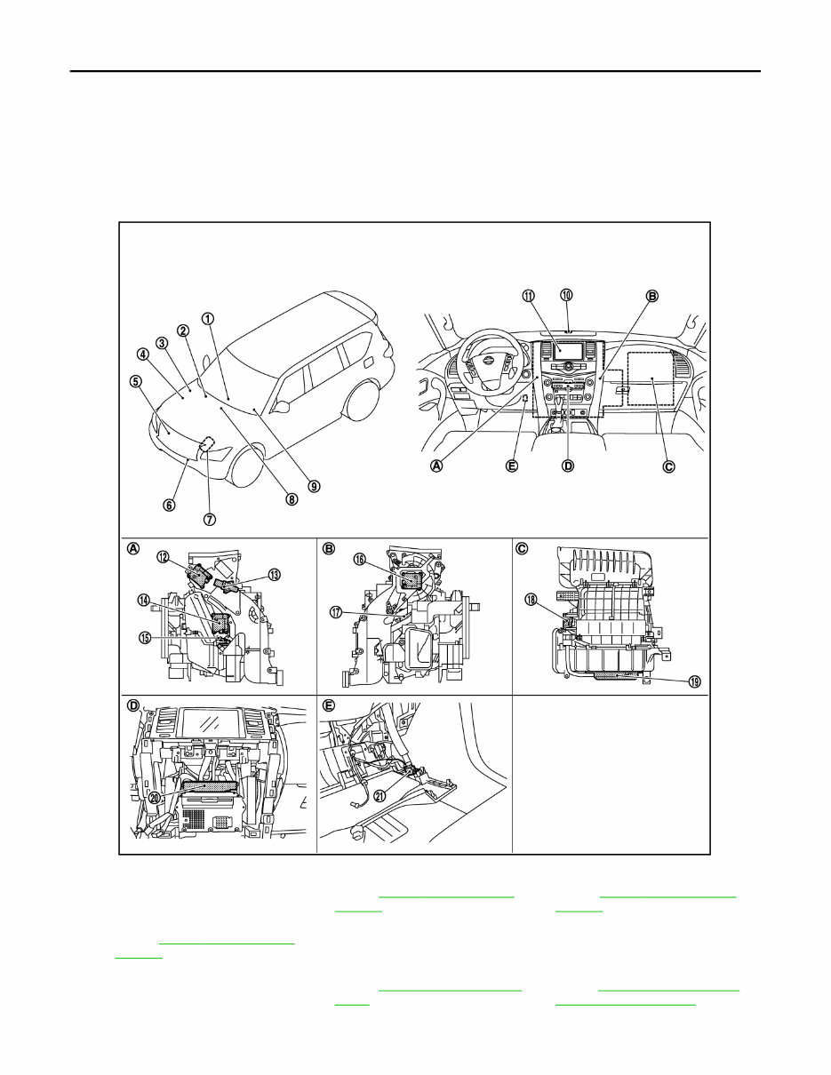
HAC-6 < SYSTEM DESCRIPTION > [AUTOMATIC AIR CONDITIONING] COMPONENT PARTS SYSTEM DESCRIPTION COMPONENT PARTS FRONT AUTOMATIC AIR CONDITIONING SYSTEM FRONT AUTOMATIC AIR CONDITIONING SYSTEM : Component Parts Location INFOID:0000000006275848 1. Preset switch 2. Engine coolant temperature sensor Refer to EC-16, " Component Parts Location " . 3. IPDM E/R Refer to PCS-4, " Component Parts Location " . 4. ECM Refer to EC-16, " Component Parts Location " 5. Refrigerant pressure sensor 6. Ambient sensor 7. Magnet clutch 8. AV control unit Refer to AV-9, " Component Parts Lo- cation " . 9. Combination meter Refer to MWI-6, " METER SYSTEM : Component Parts Location " . 10. Sunload sensor 11. Front display 12. Upper ventilator door motor JMIIA0812ZZ Revision: 2010 May 2011 QX56
COMPONENT PARTS HAC-7 < SYSTEM DESCRIPTION > [AUTOMATIC AIR CONDITIONING] C D E F G H J K L M A B HAC N O P FRONT AUTOMATIC AIR CONDITIONING SYSTEM : Component Description INFOID:0000000006275849 13. Aspirator 14. Front air mix door motor (Driver side) 15. Intake sensor 16. Front mode door motor 17. Front air mix door motor (Passenger side) 18. Intake door motor 19. Front blower motor 20. A/C auto amp. 21. Front in-vehicle sensor A. Left side of heater & cooling unit as- sembly B. Right side of heater & cooling unit as- sembly C. Back side of blower unit assembly D. Cluster lid C is removed E. Instrument lower panel LH is re- moved Component Description Ambient sensor Ambient sensor measures ambient air temperature. The sensor uses a thermistor which is sensitive to the change in temperature. The electrical resistance of the thermistor decreases as temperature increases. AV control unit AV control unit transmits front A/C control operation signal to A/C auto amp. via CAN communication line. A/C auto amp. A/C auto amp. controls front automatic air conditioning system by inputting and calculating signals from each sensor and each switch. A/C auto amp. has self-diagnosis function. Diagnosis of front automatic air conditioning system can be performed quickly. Blower unit Front blower motor Refer to HAC-12 . Intake door motor The LCU (Local Control Unit) is installed to intake door motor so as to per- form the multiplex communication control (LIN). Refer to HAC-18, " FRONT AUTOMATIC AIR CONDITIONING SYSTEM : Door Control " . Combination meter Combination meter transmits vehicle speed signal to A/C auto amp. via CAN communication line. ECM ECM controls compressor according to status of engine and refrigerant. ECM transmits engine coolant temperature signal to A/C auto amp. via CAN communication line. Engine coolant temperature sensor Engine coolant temperature sensor measures engine coolant temperature. The sensor uses a thermistor which is sensitive to the change in tempera- ture. The electrical resistance of the thermistor decreases as temperature increases. Front display Front display indicates operation status of front automatic air conditioning system. Front in-vehicle sensor Front in-vehicle sensor measures temperature of intake air that flows through aspirator to passenger room. The sensor uses a thermistor which is sensitive to the change in temperature. The electrical resistance of the thermistor decreases as temperature increases. Revision: 2010 May 2011 QX56
HAC-8 < SYSTEM DESCRIPTION > [AUTOMATIC AIR CONDITIONING] COMPONENT PARTS REAR AUTOMATIC AIR CONDITIONING SYSTEM Heater & cooling unit assembly Aspirator Refer to HAC-12 . Front air mix door motor (Driver side) The LCU (Local Control Unit) is installed to front air mix door motor (driver side) so as to perform the multiplex communication control (LIN). Refer to HAC-18, " FRONT AUTOMATIC AIR CONDITIONING SYSTEM : Door Control " . Front air mix door motor (Pas- senger side) The LCU (Local Control Unit) is installed to front air mix door motor (pas- senger side) so as to perform the multiplex communication control (LIN). Refer to HAC-18, " FRONT AUTOMATIC AIR CONDITIONING SYSTEM : Door Control " . Front mode door motor The LCU (Local Control Unit) is installed to front mode door motor so as to perform the multiplex communication control (LIN). Refer to HAC-18, " FRONT AUTOMATIC AIR CONDITIONING SYSTEM : Door Control " . Intake sensor Intake sensor measures temperature of front evaporator fin temperature. The sensor uses a thermistor which is sensitive to the change in tempera- ture. The electrical resistance of the thermistor decreases as temperature increases. Upper ventilator door motor The LCU (Local Control Unit) is installed to upper ventilator door motor so as to perform the multiplex communication control (LIN). Refer to HAC-18, " FRONT AUTOMATIC AIR CONDITIONING SYSTEM : Door Control " . IPDM E/R A/C relay is integrated in IPDM E/R. IPDM E/R operates A/C relay when A/ C compressor request signal is received from ECM via CAN communica- tion line. Magnet clutch The magnet clutch is the device that drives the compressor with the signal from IPDM E/R. Compressor is driven by the magnet clutch which is mag- netized by electric power supply. IPDM controls magnet clutch by turning the built in A/C relay to ON ⇔ OFF according to ECM request. Preset switch Preset switch is integrated with front A/C control and AV operation switch. Front A/C control operation signal is transmitted from preset switch to AV control unit via communication line. Refrigerant pressure sensor Refer to HAC-13 . Sunload sensor Sunload sensor measures sunload amount. This sensor is a dual system so that sunload for driver side and passenger side are measured separate- ly. This sensor converts sunload amount to voltage signal by photodiode and transmits to A/C auto amp.. Component Description Revision: 2010 May 2011 QX56
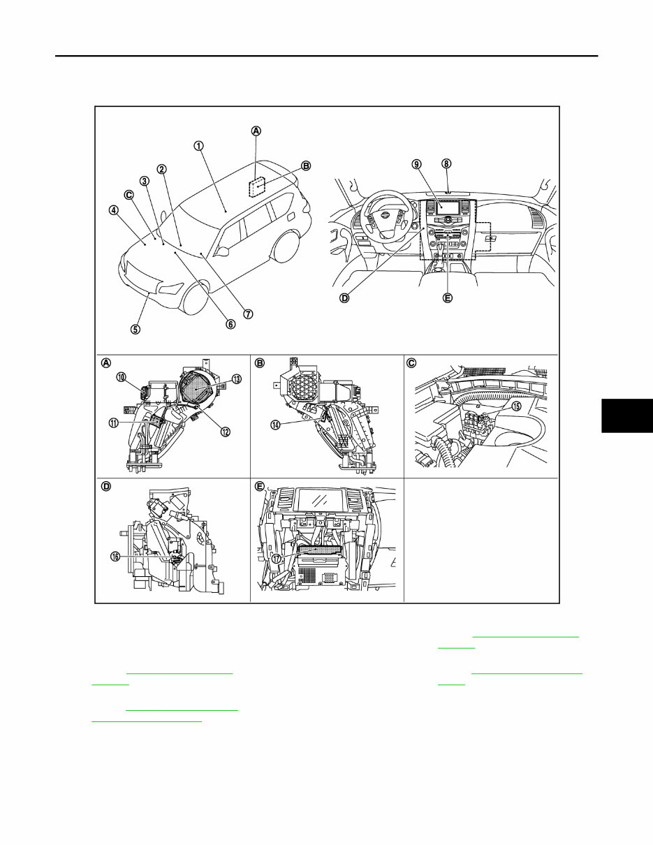
COMPONENT PARTS HAC-9 < SYSTEM DESCRIPTION > [AUTOMATIC AIR CONDITIONING] C D E F G H J K L M A B HAC N O P REAR AUTOMATIC AIR CONDITIONING SYSTEM : Component Parts Location INFOID:0000000006275850 1. Rear A/C control 2. Preset switch 3. Engine coolant temperature sensor Refer to EC-16, " Component Parts Location " . 4. ECM Refer to EC-16, " Component Parts Location " . 5. Ambient sensor 6. AV control unit Refer to AV-9, " Component Parts Lo- cation " . 7. Combination meter Refer to MWI-6, " METER SYSTEM : Component Parts Location " . 8. Sunload sensor 9. Front display 10. Rear mode door motor 11. Rear air mix door motor 12. Rear in-vehicle sensor 13. Rear blower motor 14. Rear A/C solenoid valve 15. Rear A/C relay 16. Intake sensor 17. A/C auto amp. A. Right side of rear A/C unit assembly B. Left side of rear A/C unit assembly C. Back side of engine room (RH) D. Left side of heater & cooling unit as- sembly E. Cluster lid C is removed JMIIA0813ZZ Revision: 2010 May 2011 QX56
HAC-10 < SYSTEM DESCRIPTION > [AUTOMATIC AIR CONDITIONING] COMPONENT PARTS REAR AUTOMATIC AIR CONDITIONING SYSTEM : Component Description INFOID:0000000006275851 ACCS (ADVANCED CLIMATE CONTROL SYSTEM) Component Description Ambient sensor Ambient sensor measures ambient air temperature. The sensor uses a thermistor which is sensitive to the change in temperature. The electrical resistance of the thermistor decreases as temperature increases. AV control unit AV control unit transmits front A/C control operation signal to A/C auto amp. via CAN communication line. A/C auto amp. A/C auto amp. controls rear automatic air conditioning system by inputting and calculating signals from each sensor and each switch. A/C auto amp. has self-diagnosis function. Diagnosis of rear automatic air conditioning system can be performed quickly. Combination meter Combination meter transmits vehicle speed signal to A/C auto amp. via CAN communication line. ECM ECM transmits engine coolant temperature signal to A/C auto amp. via CAN communication line. Engine coolant temperature sensor Engine coolant temperature sensor measures engine coolant temperature. The sensor uses a thermistor which is sensitive to the change in tempera- ture. The electrical resistance of the thermistor decreases as temperature increases. Front display Front display indicates operation status of rear automatic air conditioning system. Heater & cooling unit assembly Intake sensor Intake sensor measures temperature of front evaporator fin temperature. The sensor uses a thermistor which is sensitive to the change in tempera- ture. The electrical resistance of the thermistor decreases as temperature increases. Preset switch Preset switch is integrated with front A/C control and AV operation switch. Front A/C control operation signal is transmitted from preset switch to AV control unit via communication line. Rear A/C control The operation of the rear A/C control is communicated with the A/C auto amp. via communication line. Rear A/C relay Power is supplied to the rear A/C solenoid valve through rear A/C relay with A/C auto amp. control. Rear A/C unit assem- bly Rear air mix door motor The LCU (Local Control Unit) is installed to rear air mix door motor so as to perform the multiplex communication control (LIN). Refer to HAC-26, " REAR AUTOMATIC AIR CONDITIONING SYSTEM : Door Control " . Rear A/C solenoid valve Rear A/C solenoid valve operates by power supply from rear A/C relay and opens refrigerant line to rear evaporator. Rear blower motor Refer to HAC-13 . Rear in-vehicle sensor Rear in-vehicle sensor measures temperature of intake air that flows through rear blower motor to passenger room. The sensor uses a ther- mistor which is sensitive to the change in temperature. The electrical resis- tance of the thermistor decreases as temperature increases. Rear mode door motor The LCU (Local Control Unit) is installed to rear mode door motor so as to perform the multiplex communication control (LIN). Refer to HAC-26, " REAR AUTOMATIC AIR CONDITIONING SYSTEM : Door Control " . Sunload sensor Sunload sensor measures sunload amount. This sensor is a dual system so that sunload for driver side and passenger side are measured separate- ly. This sensor converts sunload amount to voltage signal by photodiode and transmits to A/C auto amp.. Revision: 2010 May 2011 QX56
If you are in need of a repair manual for your 2011 Infiniti QX56, look no further. This comprehensive manual is designed to assist both professional mechanics and DIY enthusiasts in performing a wide range of repairs and maintenance tasks on the Infiniti QX56.
Gone are the days of traditional paper manuals, as this accessible digital format provides a more cost-effective and convenient solution for obtaining the necessary repair information.
Whether you are tackling brake repairs, suspension component replacements, engine troubleshooting, or standard maintenance procedures, this manual has you covered with detailed service information for brakes, engine, suspension, steering, drivetrain, electrical systems, heating, and air conditioning.
By utilizing this manual, you can save a significant amount of money on repair costs, as it empowers you to perform the necessary work on your vehicle without relying on expensive professional services. The manual is compatible with Windows, Mac computers, smartphones, and tablets, ensuring ease of access for all users.