ACC-1 ACCELERATOR CONTROL SYSTEM B ENGINE CONTENTS C D E F G H I J K L M SECTION A ACC Revision: 2005 July 2006 M35/M45 ACCELERATOR CONTROL SYSTEM PRECAUTIONS ......................................................... 2 Precautions for Supplemental Restraint System (SRS) “AIR BAG” and “SEAT BELT PRE-TEN- SIONER” ................................................................. 2 ACCELERATOR CONTROL SYSTEM ..................... 3 Components ............................................................ 3 Removal and Installation ......................................... 3 REMOVAL ............................................................ 3 INSTALLATION .................................................... 4 INSPECTION AFTER INSTALLATION ................. 4
ACC-2 PRECAUTIONS Revision: 2005 July 2006 M35/M45 PRECAUTIONS PFP:00001 Precautions for Supplemental Restraint System (SRS) “AIR BAG” and “SEAT BELT PRE-TENSIONER” ABS00FH1 The Supplemental Restraint System such as “AIR BAG” and “SEAT BELT PRE-TENSIONER”, used along with a front seat belt, helps to reduce the risk or severity of injury to the driver and front passenger for certain types of collision. This system includes seat belt switch inputs and dual stage front air bag modules. The SRS system uses the seat belt switches to determine the front air bag deployment, and may only deploy one front air bag, depending on the severity of a collision and whether the front occupants are belted or unbelted. Information necessary to service the system safely is included in the SRS and SB section of this Service Man- ual. WARNING: ● To avoid rendering the SRS inoperative, which could increase the risk of personal injury or death in the event of a collision which would result in air bag inflation, all maintenance must be per- formed by an authorized NISSAN/INFINITI dealer. ● Improper maintenance, including incorrect removal and installation of the SRS, can lead to per- sonal injury caused by unintentional activation of the system. For removal of Spiral Cable and Air Bag Module, see the SRS section. ● Do not use electrical test equipment on any circuit related to the SRS unless instructed to in this Service Manual. SRS wiring harnesses can be identified by yellow and/or orange harnesses or harness connectors.
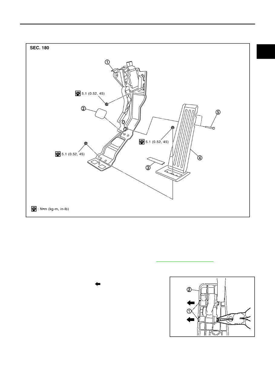
ACCELERATOR CONTROL SYSTEM ACC-3 C D E F G H I J K L M A ACC Revision: 2005 July 2006 M35/M45 ACCELERATOR CONTROL SYSTEM PFP:18005 Components ABS00FHE Removal and Installation ABS00FH2 REMOVAL 1. Disconnect accelerator pedal position sensor harness connector. 2. Remove front kicking plate and dash side finisher. Refer to EI-37, " BODY SIDE TRIM " . 3. Remove the cap and the inside mounting nut, and then disassemble the accelerator pedal pad from the floor carpet. 4. Press the pin (1) with long-nose pliers and pull them out in the direction shown by the arrow ( ). Then remove the accelerator pedal pad (2). CAUTION: Do not disengage the part (the link) other than pins. 5. Remove accelerator pedal stopper cover. 1. Accelerator pedal bracket and lever assembly 2. Accelerator pedal stopper cover 3. Cap 4. Accelerator pedal pad 5. Pin PBIC3203E KBIA3594J
ACC-4 ACCELERATOR CONTROL SYSTEM Revision: 2005 July 2006 M35/M45 6. Pull up the floor carpet. 7. Remove mounting nuts of accelerator pedal bracket. 8. Remove accelerator pedal bracket and lever assembly. CAUTION: ● Do not disassemble accelerator lever. Do not remove accelerator pedal position sensor from accelerator lever. ● Avoid impact from dropping etc. during handling. ● Be careful to keep accelerator lever away from water. INSTALLATION Installation is the reverse order of removal. INSPECTION AFTER INSTALLATION ● Make sure accelerator pedal moves smoothly within the whole operation range when it is fully depressed and released. ● Make sure accelerator pedal securely returns to the fully released position. ● For the electrical inspection of accelerator pedal position sensor, refer to the following. – VQ35DE EC-625, " DTC P2122, P2123 APP SENSOR " . – VK45DE EC-1357, " DTC P2122, P2123 APP SENSOR " . CAUTION: When harness connector of accelerator pedal position sensor is disconnected, perform “Acceler- ator Pedal Released Position Learning”. Refer to EC-95, " Accelerator Pedal Released Position Learning " (VQ35DE) or EC-805, " Accelerator Pedal Released Position Learning " (VK45DE).
If you are in need of a repair manual for your 2007 Infiniti M45, look no further. This comprehensive manual is designed to assist both professional mechanics and DIY enthusiasts in performing a wide range of repairs and maintenance tasks.
Gone are the days of purchasing traditional paper manuals at a higher cost. This accessible digital format provides a more affordable and convenient alternative, allowing you to access the same valuable information with ease.
Whether you are tackling brake repairs, suspension component replacements, engine troubleshooting, or standard maintenance procedures, this manual has you covered. It encompasses a wealth of service information, including brakes, engine, suspension, steering, drivetrain, electrical systems, heating, and air conditioning.
By utilizing this manual, you can save a significant amount of money on vehicle repairs. Professional mechanics often charge substantial fees for their services, making a DIY approach with the aid of this manual a cost-effective solution.
This 2007 Infiniti M45 repair manual is designed for compatibility with Windows, Mac computers, smartphones, and tablets, ensuring ease of use across various devices.