HAC-1 VENTILATION, HEATER & AIR CONDITIONER C D E F G H J K L M SECTION HAC A B HAC N O P CONTENTS HEATER & AIR CONDITIONING CONTROL SYSTEM AUTOMATIC AIR CONDITIONING PRECAUTION .............................................. 6 PRECAUTIONS .................................................. 6 Precaution for Supplemental Restraint System (SRS) "AIR BAG" and "SEAT BELT PRE-TEN- SIONER" .................................................................. 6 SYSTEM DESCRIPTION ............................. 7 COMPONENT PARTS ....................................... 7 AUTOMATIC AIR CONDITIONING SYSTEM (WITH FOREST AIR) .................................................. 7 AUTOMATIC AIR CONDITIONING SYSTEM (WITH FOREST AIR) : Component Parts Location ...... 7 AUTOMATIC AIR CONDITIONING SYSTEM (WITH FOREST AIR) : Component Description ...... 9 AUTOMATIC AIR CONDITIONING SYSTEM (WITHOUT FOREST AIR) ........................................ 10 AUTOMATIC AIR CONDITIONING SYSTEM (WITHOUT FOREST AIR) : Component Parts Lo- cation ...................................................................... 10 AUTOMATIC AIR CONDITIONING SYSTEM (WITHOUT FOREST AIR) : Component Descrip- tion ......................................................................... 12 FOREST AIR SYSTEM ............................................. 13 FOREST AIR SYSTEM : Component Parts Loca- tion ......................................................................... 14 FOREST AIR SYSTEM : Component Description .... 15 BLOWER UNIT ......................................................... 16 BLOWER UNIT : Aroma Motor .............................. 16 BLOWER UNIT : Blower Motor .............................. 16 BLOWER UNIT : Intake Door Motor ...................... 16 BLOWER UNIT : Power Transistor ........................ 16 HEATER & COOLING UNIT ASSEMBLY ................ 17 HEATER & COOLING UNIT ASSEMBLY : Air Mix Door Motor (Driver Side) ........................................17 HEATER & COOLING UNIT ASSEMBLY : Air Mix Door Motor (Passenger Side) .................................17 HEATER & COOLING UNIT ASSEMBLY : Aspira- tor ...........................................................................17 HEATER & COOLING UNIT ASSEMBLY : Mode Door Motor (Driver Side) ........................................17 HEATER & COOLING UNIT ASSEMBLY : Mode Door Motor (Passenger side) .................................17 HEATER & COOLING UNIT ASSEMBLY : Rear Mode Door Motor ....................................................18 HEATER & COOLING UNIT ASSEMBLY : Upper Ventilator Door Motor .............................................18 HEATER & COOLING UNIT ASSEMBLY : Upper Ventilator Door Motor (Driver Side) ........................18 HEATER & COOLING UNIT ASSEMBLY : Upper Ventilator Door Motor (Passenger Side) .................18 Refrigerant Pressure Sensor ..................................18 SYSTEM ............................................................ 19 AUTOMATIC AIR CONDITIONING SYSTEM (WITH FOREST AIR) ................................................19 AUTOMATIC AIR CONDITIONING SYSTEM (WITH FOREST AIR) : System Diagram ................19 AUTOMATIC AIR CONDITIONING SYSTEM (WITH FOREST AIR) : System Description ...........19 AUTOMATIC AIR CONDITIONING SYSTEM (WITH FOREST AIR) : Air Flow Control .................20 AUTOMATIC AIR CONDITIONING SYSTEM (WITH FOREST AIR) : Air Inlet Control ..................21 AUTOMATIC AIR CONDITIONING SYSTEM (WITH FOREST AIR) : Air Outlet Control ...............22 AUTOMATIC AIR CONDITIONING SYSTEM (WITH FOREST AIR) : Compressor Control ..........22 AUTOMATIC AIR CONDITIONING SYSTEM (WITH FOREST AIR) : Door Control ......................22 AUTOMATIC AIR CONDITIONING SYSTEM (WITH FOREST AIR) : Temperature Control .........25 Revision: 2010 June 2011 M37/M56
HAC-2 AUTOMATIC AIR CONDITIONING SYSTEM (WITH FOREST AIR) : Intelligent Key Interlock Function ................................................................. 25 AUTOMATIC AIR CONDITIONING SYSTEM (WITH FOREST AIR) : Fail-safe ............................ 26 AUTOMATIC AIR CONDITIONING SYSTEM (WITHOUT FOREST AIR) ........................................ 26 AUTOMATIC AIR CONDITIONING SYSTEM (WITHOUT FOREST AIR) : System Diagram ....... 26 AUTOMATIC AIR CONDITIONING SYSTEM (WITHOUT FOREST AIR) : System Description ... 27 AUTOMATIC AIR CONDITIONING SYSTEM (WITHOUT FOREST AIR) : Air Flow Control ........ 28 AUTOMATIC AIR CONDITIONING SYSTEM (WITHOUT FOREST AIR) : Air Inlet Control ......... 29 AUTOMATIC AIR CONDITIONING SYSTEM (WITHOUT FOREST AIR) : Air Outlet Control ...... 29 AUTOMATIC AIR CONDITIONING SYSTEM (WITHOUT FOREST AIR) : Compressor Control ... 30 AUTOMATIC AIR CONDITIONING SYSTEM (WITHOUT FOREST AIR) : Door Control .............. 30 AUTOMATIC AIR CONDITIONING SYSTEM (WITHOUT FOREST AIR) : Temperature Control ... 33 AUTOMATIC AIR CONDITIONING SYSTEM (WITHOUT FOREST AIR) : Intelligent Key Inter- lock Function ......................................................... 33 AUTOMATIC AIR CONDITIONING SYSTEM (WITHOUT FOREST AIR) : Fail-safe .................... 34 FOREST AIR SYSTEM ............................................ 34 FOREST AIR SYSTEM : System Diagram ............ 35 FOREST AIR SYSTEM : System Description ....... 35 FOREST AIR SYSTEM : Air Flow Control (Inside Odor Detecting Mechanism) .................................. 36 FOREST AIR SYSTEM : Aroma Diffuser Control ... 36 FOREST AIR SYSTEM : Automatic Defogging Control ................................................................... 37 FOREST AIR SYSTEM : Automatic Intake Control (Exhaust Gas / Outside Odor Detecting Mecha- nism) ...................................................................... 37 FOREST AIR SYSTEM : Breezy Air Control ......... 37 FOREST AIR SYSTEM : Plasmacluster Control ... 38 FOREST AIR SYSTEM : Intelligent Key Interlock Function ................................................................. 38 OPERATION ..................................................... 39 AUTOMATIC AIR CONDITIONING SYSTEM (WITH FOREST AIR) ............................................... 39 AUTOMATIC AIR CONDITIONING SYSTEM (WITH FOREST AIR) : Switch Name and Function ... 39 AUTOMATIC AIR CONDITIONING SYSTEM (WITH FOREST AIR) : Menu Displayed by Press- ing Each Switch ..................................................... 41 AUTOMATIC AIR CONDITIONING SYSTEM (WITHOUT FOREST AIR) ........................................ 41 AUTOMATIC AIR CONDITIONING SYSTEM (WITHOUT FOREST AIR) : Switch Name and Function ................................................................. 41 AUTOMATIC AIR CONDITIONING SYSTEM (WITHOUT FOREST AIR) : Menu Displayed by Pressing Each Switch ............................................ 44 FOREST AIR SYSTEM ............................................ 45 FOREST AIR SYSTEM : Switch Name and Func- tion ......................................................................... 45 FOREST AIR SYSTEM : Menu Displayed by Pressing Each Switch ............................................ 48 DIAGNOSIS SYSTEM (HVAC) ......................... 50 Description ............................................................. 50 CONSULT-III Function ........................................... 50 ECU DIAGNOSIS INFORMATION ............. 54 A/C AUTO AMP. ............................................... 54 Reference Value .................................................... 54 Fail-safe ................................................................. 62 DTC Index .............................................................. 62 ECM, IPDM E/R ................................................ 64 List of ECU Reference ........................................... 64 WIRING DIAGRAM .................................... 65 AUTOMATIC AIR CONDITIONING SYSTEM ... 65 Wiring Diagram ...................................................... 65 BASIC INSPECTION .................................. 80 DIAGNOSIS AND REPAIR WORK FLOW ....... 80 Work Flow .............................................................. 80 OPERATION INSPECTION .............................. 82 AUTOMATIC AIR CONDITIONING SYSTEM (WITH FOREST AIR) ................................................ 82 AUTOMATIC AIR CONDITIONING SYSTEM (WITH FOREST AIR) : Work Procedure ................ 82 AUTOMATIC AIR CONDITIONING SYSTEM (WITHOUT FOREST AIR) ........................................ 84 AUTOMATIC AIR CONDITIONING SYSTEM (WITHOUT FOREST AIR) : Work Procedure ........ 84 FOREST AIR SYSTEM ............................................ 86 FOREST AIR SYSTEM : Work Procedure ............. 86 ADDITIONAL SERVICE WHEN REPLACING CONTROL UNIT (A/C AUTO AMP.) ................ 89 Description ............................................................. 89 Work Procedure ..................................................... 89 CONFIGURATION (HVAC) .............................. 90 Description ............................................................. 90 Work Procedure ..................................................... 90 SYSTEM SETTING ........................................... 91 Revision: 2010 June 2011 M37/M56
HAC-3 C D E F G H J K L M A B HAC N O P AUTOMATIC AIR CONDITIONING SYSTEM .......... 91 AUTOMATIC AIR CONDITIONING SYSTEM : Temperature Setting Trimmer ................................ 91 AUTOMATIC AIR CONDITIONING SYSTEM : In- let Port Memory Function (REC) ............................ 91 AUTOMATIC AIR CONDITIONING SYSTEM : In- let Port Memory Function (FRE) ............................ 92 AUTOMATIC AIR CONDITIONING SYSTEM : Foot Position Setting Trimmer ................................ 92 FOREST AIR SYSTEM ............................................. 92 FOREST AIR SYSTEM : Aroma Fragrance Inten- sity Setting .............................................................. 92 FOREST AIR SYSTEM : Aroma Fragrance Type Setting .................................................................... 92 FOREST AIR SYSTEM : Air Flow Control (Inside Odor Detecting Mechanism) Setting ...................... 93 FOREST AIR SYSTEM : Aroma Diffuser Pres- ence Setting ........................................................... 93 DTC/CIRCUIT DIAGNOSIS ........................ 94 U1000 CAN COMM CIRCUIT ............................94 Description ............................................................. 94 DTC Logic .............................................................. 94 Diagnosis Procedure .............................................. 94 U1010 CONTROL UNIT (CAN) .........................95 Description ............................................................. 95 DTC Logic .............................................................. 95 Diagnosis Procedure .............................................. 95 B2578, B2579 IN-VEHICLE SENSOR ..............96 DTC Logic .............................................................. 96 Diagnosis Procedure .............................................. 96 Component Inspection ........................................... 97 B257B, B257C AMBIENT SENSOR .................99 DTC Logic .............................................................. 99 Diagnosis Procedure .............................................. 99 Component Inspection ......................................... 100 B2581, B2582 INTAKE SENSOR ................... 102 DTC Logic ............................................................ 102 Diagnosis Procedure ............................................ 102 Component Inspection ......................................... 103 B262A, B262B, B2657, B2658 EXHAUST GAS/OUTSIDE ODOR DETECTING SENSOR .. 105 DTC Logic ............................................................ 105 Diagnosis Procedure ............................................ 105 B2630, B2631 SUNLOAD SENSOR ............... 109 DTC Logic ............................................................ 109 Diagnosis Procedure ............................................ 109 Component Inspection ......................................... 111 B2750, B2751, B2752 AIR MIX DOOR MO- TOR (DRIVER SIDE) ....................................... 112 DTC Logic ............................................................ 112 Diagnosis Procedure ............................................ 112 Component Inspection (Motor) ............................. 115 Component Inspection (PBR) ............................... 116 B2753, B2754, B2755 AIR MIX DOOR MO- TOR (PASSENGER SIDE) .............................. 117 DTC Logic ............................................................. 117 Diagnosis Procedure ............................................ 117 Component Inspection (Motor) ............................. 120 Component Inspection (PBR) ............................... 121 B2756, B2757, B2758 MODE DOOR MOTOR (DRIVER SIDE) ............................................... 122 DTC Logic ............................................................. 122 Diagnosis Procedure ............................................ 122 Component Inspection (Motor) ............................. 125 Component Inspection (PBR) ............................... 126 B2759, B275A, B275B MODE DOOR MOTOR (PASSENGER SIDE) ...................................... 127 DTC Logic ............................................................. 127 Diagnosis Procedure ............................................ 127 Component Inspection (Motor) ............................. 131 Component Inspection (PBR) ............................... 131 B275C, B275D, B275E INTAKE DOOR MO- TOR ................................................................. 132 DTC Logic ............................................................. 132 Diagnosis Procedure ............................................ 132 Component Inspection (Motor) ............................. 136 Component Inspection (PBR) ............................... 136 B275F, B2760, B2761 UPPER VENTILATOR DOOR MOTOR ................................................ 137 DTC Logic ............................................................. 137 Diagnosis Procedure ............................................ 137 Component Inspection (Motor) ............................. 140 Component Inspection (PBR) ............................... 141 B275F, B2760, B2761 UPPER VENTILATOR DOOR MOTOR (DRIVER SIDE) ..................... 142 DTC Logic ............................................................. 142 Diagnosis Procedure ............................................ 142 Component Inspection (Motor) ............................. 145 Component Inspection (PBR) ............................... 146 B2762, B2763, B2764 REAR MODE DOOR MOTOR ........................................................... 147 DTC Logic ............................................................. 147 Diagnosis Procedure ............................................ 147 Component Inspection (Motor) ............................. 150 Component Inspection (PBR) ............................... 151 B2765, B2766, B2767 UPPER VENTILATOR DOOR MOTOR (PASSENGER SIDE) ............ 152 DTC Logic ............................................................. 152 Diagnosis Procedure ............................................ 152 Component Inspection (Motor) ............................. 155 Component Inspection (PBR) ............................... 156 Revision: 2010 June 2011 M37/M56
HAC-4 B2768, B2769, B276A AROMA MOTOR ....... 157 DTC Logic ............................................................. 157 Diagnosis Procedure ............................................ 157 Component Inspection (Motor) ............................. 160 Component Inspection (PBR) ............................... 161 B276B, B276C, B276D HUMIDITY SENSOR . 162 DTC Logic ............................................................. 162 Diagnosis Procedure ............................................ 162 Component Inspection .......................................... 165 POWER SUPPLY AND GROUND CIRCUIT .. 167 A/C AUTO AMP. ..................................................... 167 A/C AUTO AMP. : Diagnosis Procedure .............. 167 DOOR MOTOR PBR (WITH FOREST AIR) ............ 167 DOOR MOTOR PBR (WITH FOREST AIR) : Diag- nosis Procedure .................................................... 167 DOOR MOTOR PBR (WITHOUT FOREST AIR) .... 169 DOOR MOTOR PBR (WITHOUT FOREST AIR) : Diagnosis Procedure ............................................ 169 BLOWER MOTOR .......................................... 172 Diagnosis Procedure ............................................ 172 Component Inspection (Blower Motor) ................. 176 Component Inspection (Blower Relay) ................. 176 ECV (ELECTRICAL CONTROL VALVE) ....... 177 Diagnosis Procedure ............................................ 177 Component Inspection .......................................... 178 INSIDE ODOR DETECTING SENSOR ........... 179 Component Function Check ................................. 179 Diagnosis Procedure ............................................ 179 Component Inspection .......................................... 181 IONIZER .......................................................... 183 Component Function Check ................................. 183 Diagnosis Procedure ............................................ 183 MAGNET CLUTCH ......................................... 186 Component Function Check ................................. 186 Diagnosis Procedure ............................................ 186 SYMPTOM DIAGNOSIS ........................... 187 AUTOMATIC AIR CONDITIONING SYSTEM (WITH FOREST AIR) ...................................... 187 Symptom Table .................................................... 187 AUTOMATIC AIR CONDITIONING SYSTEM (WITHOUT FOREST AIR) .............................. 190 Symptom Table .................................................... 190 FOREST AIR SYSTEM ................................... 192 Symptom Table .................................................... 192 COMPRESSOR DOSE DOT OPERATE ........ 194 Description ............................................................ 194 Diagnosis Procedure ............................................ 194 INSUFFICIENT COOLING ............................... 196 Description ........................................................... 196 Diagnosis Procedure ............................................ 196 INSUFFICIENT HEATING ............................... 197 Description ........................................................... 197 Diagnosis Procedure ............................................ 197 INTELLIGENT KEY INTERLOCK FUNCTION DOES NOT OPERATE .................................... 198 Description ........................................................... 198 Diagnosis Procedure ............................................ 198 NORMAL OPERATING CONDITION .............. 199 Description ........................................................... 199 REMOVAL AND INSTALLATION ............. 200 MULTIFUNCTION SWITCH ............................ 200 Removal and Installation ...................................... 200 A/C AUTO AMP. .............................................. 201 Exploded View ..................................................... 201 Removal and Installation ...................................... 201 AMBIENT SENSOR ......................................... 202 Removal and Installation ...................................... 202 IN-VEHICLE SENSOR ..................................... 203 Removal and Installation ...................................... 203 SUNLOAD SENSOR ....................................... 204 Removal and Installation ...................................... 204 HUMIDITY SENSOR ........................................ 205 Exploded View ..................................................... 205 Removal and Installation ...................................... 205 INTAKE SENSOR ............................................ 206 Exploded View ..................................................... 206 Removal and Installation ...................................... 206 INSIDE ODOR DETECTING SENSOR ........... 207 Exploded View ..................................................... 207 Removal and Installation ...................................... 207 EXHAUST GAS/OUTSIDE ODOR SENSOR .. 208 Removal and Installation ...................................... 208 DOOR MOTOR ................................................ 209 Exploded View ..................................................... 209 MODE DOOR MOTOR ........................................... 209 MODE DOOR MOTOR : Removal and Installation . 209 AIR MIX DOOR MOTOR ........................................ 210 AIR MIX DOOR MOTOR : Removal and Installa- tion ....................................................................... 210 INTAKE DOOR MOTOR ........................................ 210 INTAKE DOOR MOTOR : Removal and Installa- tion ....................................................................... 210 Revision: 2010 June 2011 M37/M56
HAC-5 C D E F G H J K L M A B HAC N O P UPPER VENTILATOR DOOR MOTOR .................. 211 UPPER VENTILATOR DOOR MOTOR : Removal and Installation ..................................................... 211 REAR MODE DOOR MOTOR ................................ 211 REAR MODE DOOR MOTOR : Removal and In- stallation ............................................................... 211 POWER TRANSISTOR ................................... 212 Exploded View ..................................................... 212 Removal and Installation ...................................... 212 IONIZER .......................................................... 213 Exploded View ...................................................... 213 Removal and Installation ...................................... 213 AROMA UNIT ASSY ....................................... 214 Exploded View ...................................................... 214 Removal and Installation ...................................... 214 Revision: 2010 June 2011 M37/M56
HAC-6 < PRECAUTION > [AUTOMATIC AIR CONDITIONING] PRECAUTIONS PRECAUTION PRECAUTIONS Precaution for Supplemental Restraint System (SRS) "AIR BAG" and "SEAT BELT PRE-TENSIONER" INFOID:0000000005905830 The Supplemental Restraint System such as “AIR BAG” and “SEAT BELT PRE-TENSIONER”, used along with a front seat belt, helps to reduce the risk or severity of injury to the driver and front passenger for certain types of collision. This system includes seat belt switch inputs and dual stage front air bag modules. The SRS system uses the seat belt switches to determine the front air bag deployment, and may only deploy one front air bag, depending on the severity of a collision and whether the front occupants are belted or unbelted. Information necessary to service the system safely is included in the “SRS AIR BAG” and “SEAT BELT” of this Service Manual. WARNING: • To avoid rendering the SRS inoperative, which could increase the risk of personal injury or death in the event of a collision that would result in air bag inflation, all maintenance must be performed by an authorized NISSAN/INFINITI dealer. • Improper maintenance, including incorrect removal and installation of the SRS, can lead to personal injury caused by unintentional activation of the system. For removal of Spiral Cable and Air Bag Module, see the “SRS AIR BAG”. • Do not use electrical test equipment on any circuit related to the SRS unless instructed to in this Service Manual. SRS wiring harnesses can be identified by yellow and/or orange harnesses or har- ness connectors. PRECAUTIONS WHEN USING POWER TOOLS (AIR OR ELECTRIC) AND HAMMERS WARNING: • When working near the Air Bag Diagnosis Sensor Unit or other Air Bag System sensors with the ignition ON or engine running, DO NOT use air or electric power tools or strike near the sensor(s) with a hammer. Heavy vibration could activate the sensor(s) and deploy the air bag(s), possibly causing serious injury. • When using air or electric power tools or hammers, always switch the ignition OFF, disconnect the battery, and wait at least 3 minutes before performing any service. Revision: 2010 June 2011 M37/M56
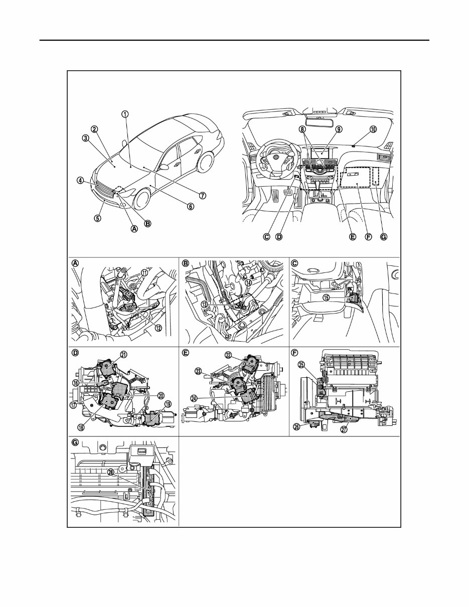
COMPONENT PARTS HAC-7 < SYSTEM DESCRIPTION > [AUTOMATIC AIR CONDITIONING] C D E F G H J K L M A B HAC N O P SYSTEM DESCRIPTION COMPONENT PARTS AUTOMATIC AIR CONDITIONING SYSTEM (WITH FOREST AIR) AUTOMATIC AIR CONDITIONING SYSTEM (WITH FOREST AIR) : Component Parts Revision: 2010 June 2011 M37/M56
HAC-8 < SYSTEM DESCRIPTION > [AUTOMATIC AIR CONDITIONING] COMPONENT PARTS Location INFOID:0000000005905635 JMIIA0763ZZ Revision: 2010 June 2011 M37/M56
COMPONENT PARTS HAC-9 < SYSTEM DESCRIPTION > [AUTOMATIC AIR CONDITIONING] C D E F G H J K L M A B HAC N O P AUTOMATIC AIR CONDITIONING SYSTEM (WITH FOREST AIR) : Component De- scription INFOID:0000000005905636 1. AV control unit Refer to AV-144, " Component Parts Location " . 2. IPDM E/R Refer to PCS-5, " IPDM E/R : Compo- nent Parts Location " . 3. ECM VQ37VHR: Refer to EC-24, " EN- GINE CONTROL SYSTEM : Com- ponent Parts Location " . VK56VD: Refer to EC-548, " EN- GINE CONTROL SYSTEM : Com- ponent Parts Location " . 4. Refrigerant pressure sensor 5. Ambient sensor 6. BCM BCS-4, " BODY CONTROL SYS- TEM : Component Parts Location " . 7. Combination meter Refer to MWI-6, " METER SYSTEM : Component Parts Location " . 8. Multifunction switch 9. Display 10. Sunload sensor 11. ECV (Electrical Control Valve) 12. Magnet clutch 13. Magnet clutch 14. ECV (Electrical Control Valve) 15. In-vehicle sensor 16. Aspirator 17. Intake sensor 18. Air mix door motor (Driver side) 19. Rear mode door motor 20. Mode door motor (Driver side) 21. Upper ventilator door motor (Driver side) 22. Upper ventilator door motor (Passen- ger side) 23. Mode door motor (Passenger side) 24. Air mix door motor (Passenger side) 25. Intake door motor 26. Power transistor 27. Blower motor 28. A/C auto amp. A. Compressor (VQ37VHR) B. Compressor (VK56VD) C. Lower instrument panel LH is re- moved D. Left side of heater & cooling unit as- sembly E. Right side of heater & cooling unit as- sembly F. Rear side of blower unit G. Instrument lower panel RH is re- moved Component parts Description Blower unit Blower motor Refer to HAC-16 . Intake door motor Refer to HAC-16 . Power transistor Refer to HAC-16 . Compressor ECV (Electrical Control Valve) ECV (electrical control valve) is installed on the compressor and controls it for emitting appropriate amount of refrigerant when necessary. Magnet clutch • Magnet clutch is the device that drives the compressor with the signal from IPDM E/R. • Compressor is driven by the magnet clutch which is magnetized by elec- tric power supply. Revision: 2010 June 2011 M37/M56
HAC-10 < SYSTEM DESCRIPTION > [AUTOMATIC AIR CONDITIONING] COMPONENT PARTS AUTOMATIC AIR CONDITIONING SYSTEM (WITHOUT FOREST AIR) AUTOMATIC AIR CONDITIONING SYSTEM (WITHOUT FOREST AIR) : Component Heater & cooling unit assembly Air mix door motor (Driver side) Refer to HAC-17 . Air mix door motor (Passenger side) Refer to HAC-17 . Aspirator Refer to HAC-17 . Intake sensor Intake sensor measures evaporator fin temperature. This sensor uses ther- mistor that decreases electrical resistance as temperature increases. Mode door motor (Driver side) Refer to HAC-17 . Mode door motor (Passenger side) Refer to HAC-17 . Rear mode door motor Refer to HAC-18 . Upper ventilator door motor (Driver side) Refer to HAC-18 . Upper ventilator door motor (Passenger side) Refer to HAC-18 . Ambient sensor Ambient sensor measures ambient air temperature. This sensor uses ther- mistor that decreases electrical resistance as temperature increases. AV control unit AV control unit transmits A/C switch operation signal to A/C auto amp. via CAN communication line. A/C auto amp. A/C auto amp. controls air conditioning system by inputting and calculating signals from each sensor and each switch. A/C auto amp. has self-diagno- sis function. Diagnosis of air conditioning system can be performed quickly. BCM BCM transmits key ID signal to A/C auto amp. via CAN communication line. Display Display indicates operation status of air conditioning system. Display has touch panel function that can be used to control air conditioning system. ECM ECM controls compressor according to status of engine and refrigerant. Engine coolant temperature sensor Engine coolant temperature sensor measures engine coolant temperature. This sensor uses thermistor that decreases electrical resistance as temper- ature increases. In-vehicle sensor In-vehicle sensor measures temperature of intake air through aspirator to passenger room. This sensor uses thermistor that decreases electrical re- sistance as temperature increases. IPDM E/R A/C relay is integrated in IPDM E/R. IPDM E/R operates A/C relay when A/ C compressor request signal is received from ECM via CAN communica- tion line. Multifunction switch Multifunction switch integrates A/C controller and AV operation switch. A/C switch operation signal is transmitted from multifunction switch to AV con- trol unit via communication line. Refrigerant pressure sensor Refer to HAC-18 . Sunload sensor Sunload sensor measures sunload amount. This sensor is a dual system so that sunload for driver side and passenger side are measured separate- ly. This sensor converts sunload amount to voltage signal by photodiode and transmits to A/C auto amp. Component parts Description Revision: 2010 June 2011 M37/M56
If you are in need of a repair manual for your 2011 Infiniti M37, look no further. Our accessible repair manual is perfect for both professional mechanics and DIY enthusiasts. In the past, traditional service manuals in book format were costly and inconvenient. Our repair manual provides the same information at a much lower cost and in a more convenient format.
Whether you need to fix the brakes, replace suspension components, get the engine running, or perform standard maintenance, this repair manual for the Infiniti M37 has you covered. It includes comprehensive service information for the brakes, engine, suspension, steering, drivetrain, electrical systems, heating, air conditioning, and more.
By utilizing this 2011 Infiniti M37 repair manual , you can save a significant amount of money on vehicle repairs. Mechanics often charge high fees for their services, making a DIY approach a cost-effective alternative. The manual is compatible with Windows, Mac computers, smartphones, and tablets, ensuring ease of use for all users.