2002-2004 Infiniti I35 (A33) Service & Repair Manual
What's Included?
Lifetime Access
Fast Download Speeds
Offline Viewing
Access Contents & Bookmarks
Full Search Facility
Print one or all pages of your manual
AUTOMATIC TRANSAXLE SECTION AT CONTENTS TROUBLE DIAGNOSIS - INDEX ....................................5 Alphabetical & P No. Index for DTC ...........................5 PRECAUTIONS ...............................................................7 Supplemental Restraint System (SRS) ″AIR BAG″ and ″SEAT BELT PRE-TENSIONER″ ...............7 Precautions for On Board Diagnostic (OBD) System of A/T and Engine...........................................7 Precautions ..................................................................8 Service Notice or Precautions .....................................9 Wiring Diagrams and Trouble Diagnosis ...................10 PREPARATION ............................................................. 11 Special Service Tools ................................................ 11 Commercial Service Tools .........................................14 OVERALL SYSTEM ......................................................15 A/T Electrical Parts Location .....................................15 Circuit Diagram ..........................................................16 Cross-sectional View .................................................17 Hydraulic Control Circuit ............................................18 Shift Mechanism ........................................................19 Control System ..........................................................28 Control Mechanism....................................................30 Control Valve .............................................................34 ON BOARD DIAGNOSTIC SYSTEM DESCRIPTION ...............................................................36 Introduction ................................................................36 OBD-II Function for A/T System................................36 One or Two Trip Detection Logic of OBD-II ..............36 OBD-II Diagnostic Trouble Code (DTC) ....................36 Malfunction Indicator Lamp (MIL) ..............................40 CONSULT-II ...............................................................40 Diagnostic Procedure Without CONSULT-II ..............51 TROUBLE DIAGNOSIS - INTRODUCTION..................57 Introduction ................................................................57 Work Flow ..................................................................61 TROUBLE DIAGNOSIS - BASIC INSPECTION ...........63 A/T Fluid Check .........................................................63 Stall Test ....................................................................63 Line Pressure Test .....................................................67 Road Test ...................................................................68 TROUBLE DIAGNOSIS - GENERAL DESCRIPTION ...............................................................86 Symptom Chart ..........................................................86 TCM Terminals and Reference Value........................97 CAN COMMUNICATION .............................................100 System Description ..................................................100 TROUBLE DIAGNOSIS FOR POWER SUPPLY........102 Wiring Diagram - AT - MAIN....................................102 Diagnostic Procedure ..............................................103 DTC P0705 PARK/NEUTRAL POSITION SWITCH ...105 Description ...............................................................105 On Board Diagnosis Logic.......................................105 Possible Cause ........................................................106 Diagnostic Trouble Code (DTC) Confirmation Procedure ................................................................106 Wiring Diagram - AT - PNP/SW...............................107 Diagnostic Procedure ..............................................108 DTC P0710 A/T FLUID TEMPERATURE SENSOR CIRCUIT ....................................................................... 111 Description ............................................................... 111 On Board Diagnosis Logic....................................... 111 Possible Cause ........................................................ 112 Diagnostic Trouble Code (DTC) Confirmation Procedure ................................................................ 112 Wiring Diagram - AT - FTS ...................................... 113 Diagnostic Procedure .............................................. 114 DTC P0720 VEHICLE SPEED SENSOR.A/T (REVOLUTION SENSOR) ........................................... 117 Description ............................................................... 117 On Board Diagnosis Logic....................................... 117 Possible Cause ........................................................ 117 Diagnostic Trouble Code (DTC) Confirmation Procedure ................................................................ 118 Wiring Diagram - AT - VSSA/T ................................ 119 Diagnostic Procedure ..............................................120 DTC P0725 ENGINE SPEED SIGNAL .......................122 Description ...............................................................122 On Board Diagnosis Logic.......................................122 Possible Cause ........................................................122 GI MA EM LC EC FE AX SU BR ST RS BT HA SC EL IDX
Diagnostic Trouble Code (DTC) Confirmation Procedure ................................................................123 Wiring Diagram - AT - ENGSS ................................124 Diagnostic Procedure ..............................................125 DTC P0731 A/T 1ST GEAR FUNCTION ....................127 Description ...............................................................127 On Board Diagnosis Logic.......................................127 Possible Cause ........................................................128 Diagnostic Trouble Code (DTC) Confirmation Procedure ................................................................128 Wiring Diagram - AT - 1ST ......................................130 Diagnostic Procedure ..............................................131 DTC P0732 A/T 2ND GEAR FUNCTION ....................133 Description ...............................................................133 On Board Diagnosis Logic.......................................133 Possible Cause ........................................................134 Diagnostic Trouble Code (DTC) Confirmation Procedure ................................................................134 Wiring Diagram - AT - 2ND......................................136 Diagnostic Procedure ..............................................137 DTC P0733 A/T 3RD GEAR FUNCTION ....................139 Description ...............................................................139 On Board Diagnosis Logic.......................................139 Possible Cause ........................................................140 Diagnostic Trouble Code (DTC) Confirmation Procedure ................................................................140 Wiring Diagram - AT - 3RD......................................142 Diagnostic Procedure ..............................................143 DTC P0734 A/T 4TH GEAR FUNCTION ....................145 Description ...............................................................145 On Board Diagnosis Logic.......................................146 Possible Cause ........................................................146 Diagnostic Trouble Code (DTC) Confirmation Procedure ................................................................147 Wiring Diagram - AT - 4TH ......................................149 Diagnostic Procedure ..............................................150 DTC P0740 TORQUE CONVERTER CLUTCH SOLENOID VALVE......................................................154 Description ...............................................................154 On Board Diagnosis Logic.......................................154 Possible Cause ........................................................154 Diagnostic Trouble Code (DTC) Confirmation Procedure ................................................................155 Wiring Diagram - AT - TCV......................................156 Diagnostic Procedure ..............................................157 DTC P0744 A/T TCC S/V FUNCTION (LOCK-UP) ....159 Description ...............................................................159 On Board Diagnosis Logic.......................................159 Possible Cause ........................................................160 Diagnostic Trouble Code (DTC) Confirmation Procedure ................................................................160 Wiring Diagram - AT - TCCSIG ...............................162 Diagnostic Procedure ..............................................163 DTC P0745 LINE PRESSURE SOLENOID VALVE ...169 Description ...............................................................169 On Board Diagnosis Logic.......................................169 Possible Cause ........................................................170 Diagnostic Trouble Code (DTC) Confirmation Procedure ................................................................170 Wiring Diagram - AT - LPSV....................................171 Diagnostic Procedure ..............................................172 DTC P0750 SHIFT SOLENOID VALVE A ..................175 Description ...............................................................175 On Board Diagnosis Logic.......................................175 Possible Cause ........................................................175 Diagnostic Trouble Code (DTC) Confirmation Procedure ................................................................176 Wiring Diagram - AT - SSV/A ..................................177 Diagnostic Procedure ..............................................178 DTC P0755 SHIFT SOLENOID VALVE B ..................180 Description ...............................................................180 On Board Diagnosis Logic.......................................180 Possible Cause ........................................................180 Diagnostic Trouble Code (DTC) Confirmation Procedure ................................................................181 Wiring Diagram - AT - SSV/B ..................................182 Diagnostic Procedure ..............................................183 DTC P1705 ACCELERATOR PEDAL POSITION SENSOR (THROTTLE POSITION SENSOR) .............185 Description ...............................................................185 On Board Diagnosis Logic.......................................186 Possible Cause ........................................................186 Diagnostic Trouble Code (DTC) Confirmation Procedure ................................................................187 Wiring Diagram - AT - TPS ......................................188 Diagnostic Procedure ..............................................189 DTC P1760 OVERRUN CLUTCH SOLENOID VALVE..........................................................................192 Description ...............................................................192 On Board Diagnosis Logic.......................................192 Possible Cause ........................................................192 Diagnostic Trouble Code (DTC) Confirmation Procedure ................................................................193 Wiring Diagram - AT - OVRCSV..............................194 Diagnostic Procedure ..............................................195 DTC BATT/FLUID TEMP SEN (A/T FLUID TEMP SENSOR CIRCUIT AND TCM POWER SOURCE) ....197 Description ...............................................................197 On Board Diagnosis Logic.......................................198 Possible Cause ........................................................198 Diagnostic Trouble Code (DTC) Confirmation Procedure ................................................................198 Wiring Diagram - AT - BA/FTS ................................199 Diagnostic Procedure ..............................................200 CONTENTS (Cont’d) AT-2
DTC VEHICLE SPEED SENSOR.MTR .......................204 Description ...............................................................204 On Board Diagnosis Logic.......................................204 Possible Cause ........................................................204 Diagnostic Trouble Code (DTC) Confirmation Procedure ................................................................205 Wiring Diagram - AT - VSSMTR..............................206 Diagnostic Procedure ..............................................207 DTC U1000 CAN COMMUNICATION LINE ...............209 Description ...............................................................209 On Board Diagnosis Logic.......................................209 Possible Cause ........................................................209 Diagnostic Trouble Code (DTC) Confirmation Procedure ................................................................210 Wiring Diagram - AT - CAN ..................................... 211 Diagnostic Procedure ..............................................212 DTC POWER TRAIN REVOLUTION SENSOR ..........213 Description ...............................................................213 On Board Diagnosis Logic.......................................213 Diagnostic Trouble Code (DTC) Confirmation Procedure ................................................................214 Wiring Diagram - AT - P/T SEN-01 .........................215 Diagnostic Procedure ..............................................216 Component Inspection .............................................217 DTC CONTROL UNIT (RAM), CONTROL UNIT (ROM) ...........................................................................218 Description ...............................................................218 On Board Diagnosis Logic.......................................218 Possible Cause ........................................................218 Diagnostic Trouble Code (DTC) Confirmation Procedure ................................................................218 Diagnostic Procedure ..............................................219 DTC CONTROL UNIT (EEP ROM) .............................220 Description ...............................................................220 On Board Diagnosis Logic.......................................220 Possible Cause ........................................................220 Diagnostic Trouble Code (DTC) Confirmation Procedure ................................................................220 Diagnostic Procedure ..............................................221 TROUBLE DIAGNOSES FOR SYMPTOMS ...............222 Wiring Diagram - AT - NONDTC .............................222 1. A/T CHECK Indicator Lamp Does Not Come On ............................................................................224 2. Engine Cannot Be Started In P and N Position..227 3. In P Position, Vehicle Moves Forward or Backward When Pushed .........................................228 4. In N Position, Vehicle Moves ..............................229 5. Large Shock. N -> R Position .............................232 6. Vehicle Does Not Creep Backward In R Position ....................................................................234 7. Vehicle Does Not Creep Forward in D, 2nd or 1st Position ..............................................................238 8. Vehicle Cannot Be Started From D 1 ...................241 9. A/T Does Not Shift: D 1 -> D 2 or Does Not Kickdown: D 4 -> D 2 ..................................................244 10. A/T Does Not Shift: D 2 -> D 3 .............................247 11. A/T Does Not Shift: D 3 -> D 4 .............................250 12. A/T Does Not Perform Lock-up .........................253 13. A/T Does Not Hold Lock-up Condition ..............255 14. Lock-up Is Not Released ...................................257 15. Engine Speed Does Not Return To Idle (Light Braking D 4 -> D 3 ).....................................................258 16. Vehicle Does Not Start From D 1 .......................261 17. A/T Does Not Shift: D 4 -> D 3 , When 3rd Position Switch ON -> OFF .....................................262 18. A/T Does Not Shift: D 3 -> 2 2 , When Selector Lever D -> 2nd Position ..........................................263 19. A/T Does Not Shift: 2 2 -> 1 1 , When Selector Lever 2nd -> 1st Position ........................................264 20. Vehicle Does Not Decelerate By Engine Brake........................................................................265 21. TCM Self-diagnosis Does Not Activate [PNP & 3rd Position Switches and APP Sensor* Circuit Checks] ....................................................................265 A/T SHIFT LOCK SYSTEM.........................................272 Description ...............................................................272 Shift Lock System Electrical Parts Location............272 Wiring Diagram - SHIFT - ........................................273 Shift Lock Control Unit Reference Values ...............274 Component Inspection .............................................275 SHIFT CONTROL SYSTEM ........................................277 Control Cable ...........................................................277 ON-VEHICLE SERVICE ..............................................278 Control Valve Assembly and Accumulators .............278 Revolution Sensor Replacement .............................279 Park/Neutral Position (PNP) Switch Adjustment .....279 Control Cable Adjustment ........................................280 Differential Side Oil Seal Replacement ...................280 REMOVAL AND INSTALLATION ...............................281 Removal ...................................................................281 Installation ................................................................282 OVERHAUL .................................................................284 Components.............................................................284 Oil Channel ..............................................................287 Locations of Adjusting Shims, Needle Bearings, Thrust Washers and Snap Rings ............................288 DISASSEMBLY............................................................289 REPAIR FOR COMPONENT PARTS .........................303 Manual Shaft............................................................303 Oil Pump ..................................................................306 Control Valve Assembly ...........................................310 Control Valve Upper Body .......................................318 Control Valve Lower Body .......................................322 Reverse Clutch ........................................................324 GI MA EM LC EC FE AX SU BR ST RS BT HA SC EL IDX CONTENTS (Cont’d) AT-3
High Clutch ..............................................................327 Forward and Overrun Clutches ...............................332 Low & Reverse Brake..............................................337 Rear Internal Gear, Forward Clutch Hub and Overrun Clutch Hub .................................................340 Output Shaft, Idler Gear, Reduction Pinion Gear and Bearing Retainer...............................................344 Band Servo Piston Assembly ..................................349 Final Drive................................................................354 ASSEMBLY..................................................................358 Assembly (1) ............................................................358 Adjustment (1) .........................................................358 Assembly (2) ............................................................363 Adjustment (2) .........................................................369 Assembly (3) ............................................................371 SERVICE DATA AND SPECIFICATIONS (SDS) .......377 General Specifications .............................................377 Shift Schedule..........................................................377 Stall Revolution ........................................................377 Line Pressure...........................................................378 Control Valves..........................................................378 Accumulator .............................................................378 Clutch and Brakes ...................................................379 Final Drive................................................................381 Planetary Carrier and Oil Pump ..............................382 Input Shaft ...............................................................383 Reduction Pinion Gear ............................................383 Band Servo ..............................................................384 Output Shaft.............................................................384 Bearing Retainer ......................................................385 Total End Play..........................................................385 Reverse Clutch End Play ........................................385 Removal and Installation .........................................386 Shift Solenoid Valves ...............................................386 Solenoid Valves .......................................................386 A/T Fluid Temperature Sensor.................................386 Revolution Sensor (For Speed Sensor) ..................386 Dropping Resistor ....................................................386 Power Train Revolution Sensor ...............................386 CONTENTS (Cont’d) AT-4
Alphabetical & P No. Index for DTC NHAT0001 ALPHABETICAL INDEX FOR DTC NHAT0001S01 Items (CONSULT-II screen terms) DTC Reference page CONSULT-II GST*1 A/T 1ST GR FNCTN P0731 AT-127 A/T 2ND GR FNCTN P0732 AT-133 A/T 3RD GR FNCTN P0733 AT-139 A/T 4TH GR FNCTN P0734 AT-145 A/T TCC S/V FNCTN P0744 AT-159 ATF TEMP SEN/CIRC P0710 AT-111 CAN COMM CIRCUIT U1000 AT-209 ENGINE SPEED SIG P0725 AT-122 L/PRESS SOL/CIRC P0745 AT-169 O/R CLTCH SOL/CIRC P1760 AT-192 PNP SW/CIRC P0705 AT-105 SFT SOL A/CIRC*2 P0750 AT-175 SFT SOL B/CIRC*2 P0755 AT-180 TCC SOLENOID/CIRC P0740 AT-154 TP SEN/CIRC A/T*2 P1705 AT-185 VEH SPD SEN/CIR AT*3 P0720 AT-117 *1: These numbers are prescribed by SAE J2012. *2: When the fail-safe operation occurs, the MIL illuminates. *3: The MIL illuminates when both the “Revolution sensor signal” and the “Vehicle speed sensor signal” meet the fail-safe condition at the same time. GI MA EM LC EC FE AX SU BR ST RS BT HA SC EL IDX TROUBLE DIAGNOSIS — INDEX Alphabetical & P No. Index for DTC AT-5
P NO. INDEX FOR DTC =NHAT0001S02 DTC Items (CONSULT-II screen terms) Reference page CONSULT-II GST*1 P0705 PNP SW/CIRC AT-105 P0710 ATF TEMP SEN/CIRC AT-111 P0720 VEH SPD SEN/CIR AT*3 AT-117 P0725 ENGINE SPEED SIG AT-122 P0731 A/T 1ST GR FNCTN AT-127 P0732 A/T 2ND GR FNCTN AT-133 P0733 A/T 3RD GR FNCTN AT-139 P0734 A/T 4TH GR FNCTN AT-145 P0740 TCC SOLENOID/CIRC AT-154 P0744 A/T TCC S/V FNCTN AT-159 P0745 L/PRESS SOL/CIRC AT-169 P0750 SFT SOL A/CIRC*2 AT-175 P0755 SFT SOL B/CIRC*2 AT-180 P1705 TP SEN/CIRC A/T*2 AT-185 P1760 O/R CLTCH SOL/CIRC AT-192 U1000 CAN COMM CIRCUIT AT-209 *1: These numbers are prescribed by SAE J2012. *2: When the fail-safe operation occurs, the MIL illuminates. *3: The MIL illuminates when both the “Revolution sensor signal” and the “Vehicle speed sensor signal” meet the fail-safe condition at the same time. TROUBLE DIAGNOSIS — INDEX Alphabetical & P No. Index for DTC (Cont’d) AT-6
Supplemental Restraint System (SRS) “AIR BAG” and “SEAT BELT PRE-TENSIONER” NHAT0002 The Supplemental Restraint System such as “AIR BAG” and “SEAT BELT PRE-TENSIONER” used along with a seat belt, helps to reduce the risk or severity of injury to the driver and front passenger for certain types of collision. This system includes seat belt switch inputs and dual stage front air bag modules. The SRS system uses the seat belt switches to determine the front air bag deployment, and may only deploy one front air bag, depending on the severity of a collision and whether the front occupants are belted or unbelted. The SRS system composition which is available to INFINITI I35 is as follows (The composition varies according to optional equipment.): I For a frontal collision The Supplemental Restraint System consists of driver air bag module (located in the center of the steer- ing wheel), front passenger air bag module (located on the instrument panel on passenger side), seat belt pre-tensioners, a diagnosis sensor unit, crash zone sensor, warning lamp, wiring harness and spiral cable. I For a side collision The Supplemental Restraint System consists of front side air bag module (located in the outer side of front seat), satellite sensor, diagnosis sensor unit (one of components of air bags for a frontal collision), wiring harness, warning lamp (one of components of air bags for a frontal collision). Information necessary to service the system safely is included in the RS section of this Service Manual. WARNING: I To avoid rendering the SRS inoperative, which could increase the risk of personal injury or death in the event of a collision which would result in air bag inflation, all maintenance should be per- formed by an authorized INFINITI dealer. I Improper maintenance, including incorrect removal and installation of the SRS, can lead to per- sonal injury caused by unintentional activation of the system. For removal of Spiral Cable and Air Bag Module, see the RS section. I Do not use electrical test equipment on any circuit related to the SRS unless instructed to in this Service Manual. SRS wiring harnesses can be identified by yellow and/or orange harness connec- tor (and by yellow harness protector or yellow insulation tape before the harness connectors). Precautions for On Board Diagnostic (OBD) System of A/T and Engine NHAT0003 The ECM has an on board diagnostic system. It will light up the malfunction indicator lamp (MIL) to warn the driver of a malfunction causing emission deterioration. CAUTION: I Be sure to turn the ignition switch OFF and disconnect the negative battery terminal before any repair or inspection work. The open/short circuit of related switches, sensors, solenoid valves, etc. will cause the MIL to light up. I Be sure to connect and lock the connectors securely after work. A loose (unlocked) connector will cause the MIL to light up due to an open circuit. (Be sure the connector is free from water, grease, dirt, bent terminals, etc.) I Be sure to route and secure the harnesses properly after work. Interference of the harness with a bracket, etc. may cause the MIL to light up due to a short circuit. I Be sure to connect rubber tubes properly after work. A misconnected or disconnected rubber tube may cause the MIL to light up due to a malfunction of the EGR system or fuel injection system, etc. I Be sure to erase the unnecessary malfunction information (repairs completed) from the TCM or ECM before returning the vehicle to the customer. GI MA EM LC EC FE AX SU BR ST RS BT HA SC EL IDX PRECAUTIONS Supplemental Restraint System (SRS) “AIR BAG” and “SEAT BELT PRE-TENSIONER” AT-7
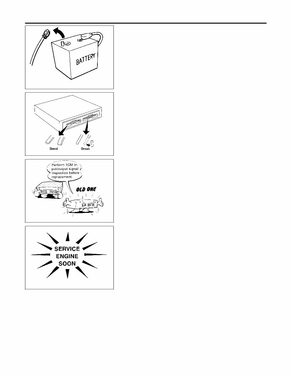
SEF289H Precautions NHAT0004 I Before connecting or disconnecting the TCM harness connector, turn ignition switch OFF and disconnect nega- tive battery terminal. Failure to do so may damage the TCM. Because battery voltage is applied to TCM even if ignition switch is turned off. AAT470A I When connecting or disconnecting pin connectors into or from TCM, take care not to damage pin terminals (bend or break). Make sure that there are not any bends or breaks on TCM pin terminal, when connecting pin connectors. MEF040DA I Before replacing TCM, perform TCM input/output signal inspection and make sure whether TCM functions prop- erly or not. (See page AT-97.) SAT964I I After performing each TROUBLE DIAGNOSIS, perform “DTC (Diagnostic Trouble Code) CONFIRMATION PROCE- DURE”. The DTC should not be displayed in the “DTC CONFIRMA- TION PROCEDURE” if the repair is completed. I Before proceeding with disassembly, thoroughly clean the out- side of the transaxle. It is important to prevent the internal parts from becoming contaminated by dirt or other foreign matter. I Disassembly should be done in a clean work area. I Use lint-free cloth or towels for wiping parts clean. Common shop rags can leave fibers that could interfere with the opera- tion of the transaxle. I Place disassembled parts in order for easier and proper assembly. I All parts should be carefully cleaned with a general purpose, non-flammable solvent before inspection or reassembly. PRECAUTIONS Precautions AT-8
I Gaskets, seals and O-rings should be replaced any time the transaxle is disassembled. I It is very important to perform functional tests whenever they are indicated. I The valve body contains precision parts and requires extreme care when parts are removed and serviced. Place disas- sembled valve body parts in order for easier and proper assembly. Care will also prevent springs and small parts from becoming scattered or lost. I Properly installed valves, sleeves, plugs, etc. will slide along bores in valve body under their own weight. I Before assembly, apply a coat of recommended ATF to all parts. Apply petroleum jelly to protect O-rings and seals, or hold bearings and washers in place during assembly. Do not use grease. I Extreme care should be taken to avoid damage to O-rings, seals and gaskets when assembling. I Replace ATF cooler if excessive foreign material is found in oil pan or clogging strainer. Refer to “ATF COOLER SERVICE” (Refer to AT-10). I After overhaul, refill the transaxle with new ATF. I When the A/T drain plug is removed, only some of the fluid is drained. Old A/T fluid will remain in torque converter and ATF cooling system. Always follow the procedures under MA-21, “Changing A/T Fluid” when changing A/T fluid. Service Notice or Precautions NHAT0005 FAIL-SAFE NHAT0005S01 The TCM has an electronic Fail-Safe (limp home mode). This allows the vehicle to be driven even if a major electrical input/output device circuit is damaged. Under Fail-Safe, the vehicle always runs in third gear, even with a shift lever position of 1st, 2nd or D. The customer may complain of sluggish or poor acceleration. When the ignition key is turned ON following Fail-Safe operation, A/T CHECK indicator lamp blinks for about 8 seconds. [For “TCM Self-diagnostic Procedure (No Tools)”, refer toAT-51.] The blinking of the A/T CHECK indicator lamp for about 8 seconds will appear only once and be cleared. The customer may resume normal driving conditions. Always follow the “Work Flow” (Refer to AT-61). The SELF-DIAGNOSIS results will be as follows: I The first SELF-DIAGNOSIS will indicate damage to the vehicle speed sensor or the revolution sensor. I During the next SELF-DIAGNOSIS, performed after checking the sensor, no damages will be indicated. TORQUE CONVERTER SERVICE NHAT0005S02 The torque converter should be replaced under any of the following conditions: I External leaks in the hub weld area. I Converter hub is scored or damaged. I Converter pilot is broken, damaged or fits poorly into crankshaft. I Steel particles are found after flushing the cooler and cooler lines. I Pump is damaged or steel particles are found in the converter. GI MA EM LC EC FE AX SU BR ST RS BT HA SC EL IDX PRECAUTIONS Precautions (Cont’d) AT-9
I Vehicle has TCC shudder and/or no TCC apply. Replace only after all hydraulic and electrical diagnoses have been made. (Converter clutch material may be glazed.) I Converter is contaminated with engine coolant containing antifreeze. I Internal failure of stator roller clutch. I Heavy clutch debris due to overheating (blue converter). I Steel particles or clutch lining material found in fluid filter or on magnet when no internal parts in unit are worn or damaged — indicates that lining material came from converter. The torque converter should not be replaced if: I The fluid has an odor, is discolored, and there is no evidence of metal or clutch facing particles. I The threads in one or more of the converter bolt holes are damaged. I Transaxle malfunction did not display evidence of damaged or worn internal parts, steel particles or clutch plate lining material in unit and inside the fluid filter. I Vehicle has been exposed to high mileage (only). The exception may be where the torque converter clutch dampener plate lining has seen excess wear by vehicles operated in heavy and/or constant traffic, such as taxi, delivery or police use. ATF COOLER SERVICE NHAT0005S03 If A/T fluid contains frictional material (clutches, bands, etc.), replace radiator and flush cooler line using cleaning solvent and compressed air after repair of A/T. Refer to LC-21, “Radiator”. OBD-II SELF-DIAGNOSIS NHAT0005S04 I A/T self-diagnosis is performed by the TCM in combination with the ECM. The results can be read through the blinking pattern of the A/T CHECK indicator lamp or the malfunction indicator lamp (MIL). Refer to the table on AT-42 for the indicator used to display each self-diagnostic result. I The self-diagnostic results indicated by the MIL are automatically stored in both the ECM and TCM memories. Always perform the procedure “HOW TO ERASE DTC” on AT-38 to complete the repair and avoid unnecessary blinking of the MIL. I The following self-diagnostic items can be detected using ECM self-diagnostic results mode* only when the A/T CHECK indicator lamp does not indicate any malfunctions. - park/neutral position (PNP) switch - A/T 1st, 2nd, 3rd, or 4th gear function - A/T TCC S/V function (lock-up). *: For details of OBD-II, refer to EC-75, “ON BOARD DIAGNOSTIC SYSTEM DESCRIPTION”. I Certain systems and components, especially those related to OBD, may use a new style slide- locking type harness connector. For description and how to disconnect, refer to EL-7, “Description”. Wiring Diagrams and Trouble Diagnosis NHAT0006 When you read wiring diagrams, refer to the following: I GI-11, “HOW TO READ WIRING DIAGRAMS” I EL-11, “POWER SUPPLY ROUTING” for power distribution circuit When you perform trouble diagnosis, refer to the following: I GI-35, “HOW TO FOLLOW TEST GROUPS IN TROUBLE DIAGNOSES” I GI-24, “HOW TO PERFORM EFFICIENT DIAGNOSIS FOR AN ELECTRICAL INCIDENT” PRECAUTIONS Service Notice or Precautions (Cont’d) AT-10
2002-2004 Infiniti I35 (A33) Service & Repair Manual
Format: .PDF
Printable: Yes
Language: English
Compatibility: Compatible with various electronic devices including PC, Mac, Android, and Apple smartphones and tablets
Requirements: Requires Adobe Reader (free)
Whether you are a professional mechanic or a DIY enthusiast, this auto repair manual provides comprehensive troubleshooting and replacement procedures recommended by the manufacturer. It includes step-by-step instructions, clear images, and exploded-view illustrations.
Regular maintenance is essential for the durability of your vehicle. Over time, certain parts will wear out and require replacement. A reliable car repair manual is invaluable, offering manufacturer-recommended troubleshooting charts and replacement procedures to help you save on repairs, enhance your vehicle's reliability, and minimize visits to the repair shop.
This digital manual is easily accessible on various electronic devices such as smartphones, tablets, iPads, PCs, and Macs. It eliminates the hassle of searching through numerous pages and the inconvenience of dealing with greasy, torn, or lost pages. Additionally, you can conveniently search, screenshot, and bookmark information, making it more practical than a traditional bound manual.
Should you prefer a physical copy, you also have the option to print the manual.
Recently Viewed
5,521,897Happy Clients
2,594,462eManuals
1,120,453Trusted Sellers
15Years in Business
Price:
Actual Price:
2002-2004 Infiniti I35 (A33) Service & Repair Manual