

2006-Onwards Infinity G35 Service & Repair Manual
What's Included?
Fast Download Speeds
Offline Viewing
Access Contents & Bookmarks
Full Search Facility
Print one or all pages of your manual

ACC-1
ACCELERATOR CONTROL SYSTEM
B ENGINE
CONTENTS
C
D
E
F
G
H
I
J
K
L
M
SECTION
A
ACC
Revision: 2006 August 2006 G35 Coupe
ACCELERATOR CONTROL SYSTEM
PRECAUTIONS ......................................................... 2
Precautions for Supplemental Restraint System
(SRS) “AIR BAG” and “SEAT BELT PRE-TEN-
SIONER” ................................................................. 2
Precautions for Battery Service ............................... 2
ACCELERATOR CONTROL SYSTEM ..................... 3
Components ............................................................ 3
Removal and Installation ......................................... 3
REMOVAL ............................................................ 3
INSTALLATION .................................................... 3
INSPECTION AFTER INSTALLATION ................. 3

ACC-2
PRECAUTIONS
Revision: 2006 August 2006 G35 Coupe
PRECAUTIONS PFP:00001
Precautions for Supplemental Restraint System (SRS) “AIR BAG” and “SEAT
BELT PRE-TENSIONER” NBS00137
The Supplemental Restraint System such as “AIR BAG” and “SEAT BELT PRE-TENSIONER”, used along
with a front seat belt, helps to reduce the risk or severity of injury to the driver and front passenger for certain
types of collision. This system includes seat belt switch inputs and dual stage front air bag modules. The SRS
system uses the seat belt switches to determine the front air bag deployment, and may only deploy one front
air bag, depending on the severity of a collision and whether the front occupants are belted or unbelted.
Information necessary to service the system safely is included in the SRS and SB section of this Service Man-
ual.
WARNING:
● To avoid rendering the SRS inoperative, which could increase the risk of personal injury or death
in the event of a collision which would result in air bag inflation, all maintenance must be per-
formed by an authorized NISSAN/INFINITI dealer.
● Improper maintenance, including incorrect removal and installation of the SRS, can lead to per-
sonal injury caused by unintentional activation of the system. For removal of Spiral Cable and Air
Bag Module, see the SRS section.
● Do not use electrical test equipment on any circuit related to the SRS unless instructed to in this
Service Manual. SRS wiring harnesses can be identified by yellow and/or orange harnesses or
harness connectors.
Precautions for Battery Service NBS00138
Before disconnecting the battery, lower both the driver and passenger windows. This will prevent any interfer-
ence between the window edge and the vehicle when the door is opened/closed. During normal operation, the
window slightly raises and lowers automatically to prevent any window to vehicle interference. The automatic
window function will not work with the battery disconnected.
ACCELERATOR CONTROL SYSTEM
ACC-3
C
D
E
F
G
H
I
J
K
L
M
A
ACC
Revision: 2006 August 2006 G35 Coupe
ACCELERATOR CONTROL SYSTEM PFP:18005
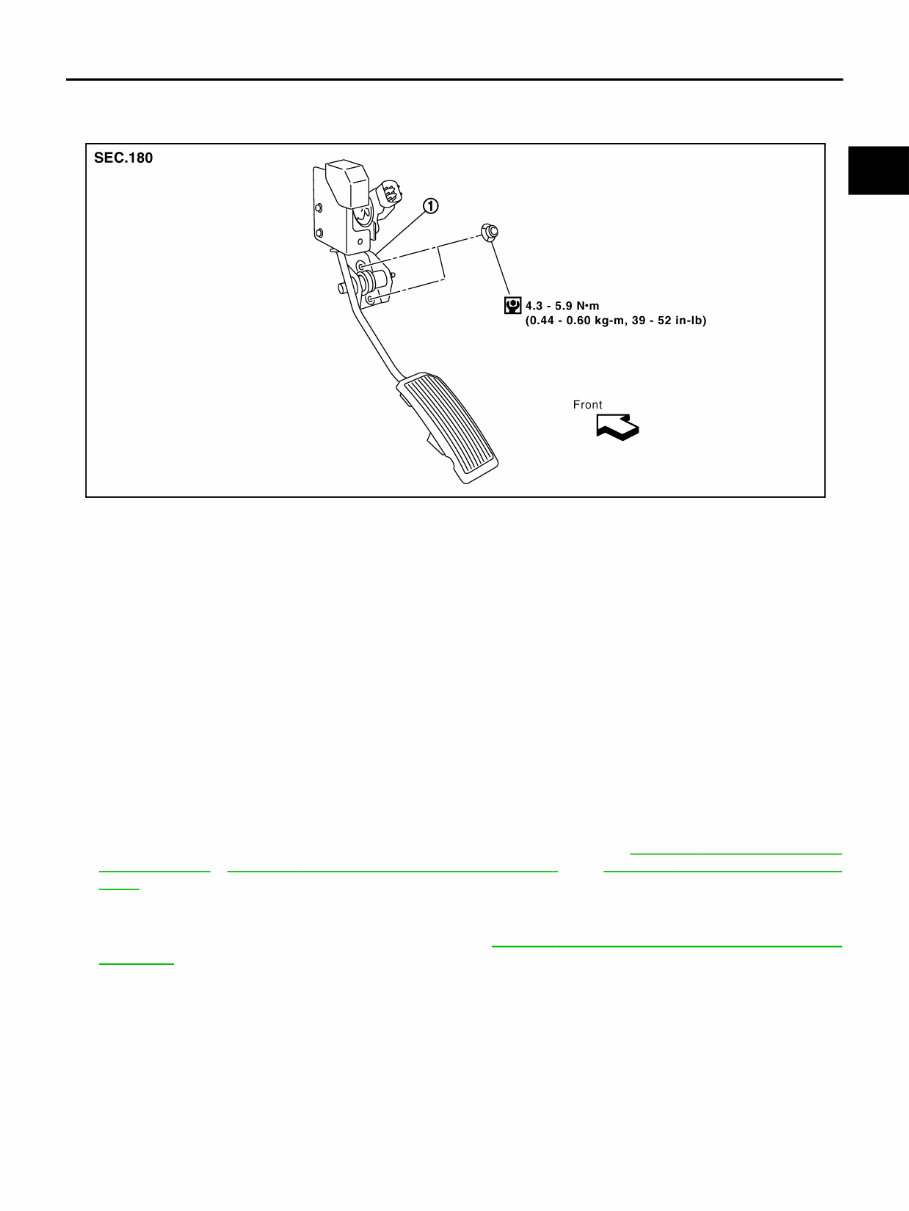
Components NBS00139
Removal and Installation NBS0013A
REMOVAL
1. Disconnect accelerator pedal position sensor harness connector.
2. Loosen nuts, and remove accelerator pedal assembly.
CAUTION:
● Do not disassemble accelerator pedal assembly. Do not remove accelerator pedal position sen-
sor from accelerator pedal assembly.
● Avoid impact from dropping etc. during handling.
● Be careful to keep accelerator pedal assembly away from water.
INSTALLATION
Install in the reverse order of removal.
INSPECTION AFTER INSTALLATION
● Make sure that accelerator pedal moves smoothly within the whole operation range.
● Make sure that accelerator pedal securely returns to the original position.
● For the electrical inspection of accelerator pedal position sensor, refer to EC-592, " DTC P2122, P2123
APP SENSOR " , EC-599, " DTC P2127, P2128 APP SENSOR " and EC-613, " DTC P2138 APP SEN-
SOR " .
CAUTION:
When harness connector of accelerator pedal position sensor is disconnected, perform “Acceler-
ator Pedal Released Position Learning”. Refer to EC-78, " Accelerator Pedal Released Position
Learning " .
1. Accelerator pedal assembly
PBIC2080E

ACC-4
ACCELERATOR CONTROL SYSTEM
Revision: 2006 August 2006 G35 Coupe
You're Reading a Preview
What's Included?
Fast Download Speeds
Offline Viewing
Access Contents & Bookmarks
Full Search Facility
Print one or all pages of your manual
$31.99
Viewed 61 Times Today


Secure transaction
What's Included?
Fast Download Speeds
Offline Viewing
Access Contents & Bookmarks
Full Search Facility
Print one or all pages of your manual
$31.99
The Infinity G35 Service Repair Manual is a comprehensive guide designed for owners of the Infinity G35 models. This manual is specifically intended for models released in 2006 onwards.
Featuring detailed instructions and step-by-step illustrations, this manual is perfect for both experienced mechanics and those new to DIY repairs. Whether you need to perform routine maintenance or tackle major repairs, this manual provides you with all the information you need.
Key features of the Infinity G35 Service Repair Manual include:
- Comprehensive coverage of all major systems and components
- Exploded diagrams and illustrations for easy understanding
- Troubleshooting guides for common issues
- Maintenance schedules and procedures
- Electrical wiring diagrams
- Diagnostic codes and explanations
Models covered in this manual:
- Infinity G35 - 2006
- Infinity G35 - 2007
- Infinity G35 - 2008
- Infinity G35 - 2009
- Infinity G35 - 2010
- Infinity G35 - 2011
Invest in the Infinity G35 Service Repair Manual today and gain the knowledge and confidence to maintain and repair your vehicle with ease.


