


ACC-1
ACCELERATOR CONTROL SYSTEM
B ENGINE
CONTENTS
C
D
E
F
G
H
I
J
K
L
M
SECTION ACC
A
ACC
Revision: 2006 December 2006 FX35/FX45
ACCELERATOR CONTROL SYSTEM
PRECAUTIONS ......................................................... 2
Precautions for Supplemental Restraint System
(SRS) “AIR BAG” and “SEAT BELT PRE-TEN-
SIONER” ................................................................. 2
ACCELERATOR CONTROL SYSTEM ..................... 3
Components ............................................................ 3
Removal and Installation ......................................... 3
REMOVAL ............................................................ 3
INSTALLATION .................................................... 3
INSPECTION AFTER INSTALLATION ................. 3

ACC-2
PRECAUTIONS
Revision: 2006 December 2006 FX35/FX45
PRECAUTIONS PFP:00001
Precautions for Supplemental Restraint System (SRS) “AIR BAG” and “SEAT
BELT PRE-TENSIONER” NBS004IP
The Supplemental Restraint System such as “AIR BAG” and “SEAT BELT PRE-TENSIONER”, used along
with a front seat belt, helps to reduce the risk or severity of injury to the driver and front passenger for certain
types of collision. This system includes seat belt switch inputs and dual stage front air bag modules. The SRS
system uses the seat belt switches to determine the front air bag deployment, and may only deploy one front
air bag, depending on the severity of a collision and whether the front occupants are belted or unbelted.
Information necessary to service the system safely is included in the SRS and SB section of this Service Man-
ual.
WARNING:
● To avoid rendering the SRS inoperative, which could increase the risk of personal injury or death
in the event of a collision which would result in air bag inflation, all maintenance must be per-
formed by an authorized NISSAN/INFINITI dealer.
● Improper maintenance, including incorrect removal and installation of the SRS, can lead to per-
sonal injury caused by unintentional activation of the system. For removal of Spiral Cable and Air
Bag Module, see the SRS section.
● Do not use electrical test equipment on any circuit related to the SRS unless instructed to in this
Service Manual. SRS wiring harnesses can be identified by yellow and/or orange harnesses or
harness connectors.
ACCELERATOR CONTROL SYSTEM
ACC-3
C
D
E
F
G
H
I
J
K
L
M
A
ACC
Revision: 2006 December 2006 FX35/FX45
ACCELERATOR CONTROL SYSTEM PFP:18005
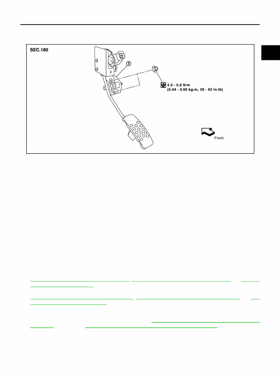
Components NBS004IQ
Removal and Installation NBS005S6
REMOVAL
1. Disconnect accelerator pedal position sensor harness connector.
2. Loosen mounting nuts, and remove accelerator pedal assembly.
CAUTION:
● Do not disassemble accelerator pedal assembly. Do not remove accelerator pedal position sen-
sor from accelerator pedal assembly.
● Avoid impact from dropping etc. during handling.
● Be careful to keep accelerator pedal assembly away from water.
INSTALLATION
Installation is the reverse order of removal.
INSPECTION AFTER INSTALLATION
● Make sure accelerator pedal moves smoothly within the whole operation range when it is fully depressed
and released.
● Make sure accelerator pedal securely returns to the fully released position.
● For the electrical inspection of accelerator pedal position sensor, refer to the following.
– VQ35DE
EC-575, " DTC P2122, P2123 APP SENSOR " , EC-582, " DTC P2127, P2128 APP SENSOR " and EC-596,
" DTC P2138 APP SENSOR "
– VK45DE
EC-1254, " DTC P2122, P2123 APP SENSOR " , EC-1261, " DTC P2127, P2128 APP SENSOR " and EC-
1275, " DTC P2138 APP SENSOR "
CAUTION:
When harness connector of accelerator pedal position sensor is disconnected, perform “Acceler-
ator Pedal Released Position Learning”. Refer to EC-84, " Accelerator Pedal Released Position
Learning " (VQ35DE) or EC-743, " Accelerator Pedal Released Position Learning " (VK45DE).
1. Accelerator pedal assembly
SBIA0332E

ACC-4
ACCELERATOR CONTROL SYSTEM
Revision: 2006 December 2006 FX35/FX45
You're Reading a Preview
What's Included?
Fast Download Speeds
Offline Viewing
Access Contents & Bookmarks
Full Search Facility
Print one or all pages of your manual
$27.99
2006-2008 Infinity FX45, FX35 Service Repair Manual
Viewed 11 Times Today

What's Included?
Fast Download Speeds
Offline Viewing
Access Contents & Bookmarks
Full Search Facility
Print one or all pages of your manual
$27.99

Secure transaction
What's Included?
Fast Download Speeds
Offline Viewing
Access Contents & Bookmarks
Full Search Facility
Print one or all pages of your manual
Description
The manual you will receive contains all the necessary instructions for vehicle repairs, covering everything from the front to the back of your car. It is utilized by professional mechanics and DIY enthusiasts alike, making it a valuable resource for saving money on car maintenance.
Inside, you will find a wealth of technical information, including illustrations, diagrams, technical specifications, and detailed explanations for each repair task. Even with basic mechanical knowledge, you can easily understand and perform the servicing and repairs, ensuring your car runs at its best.
The contents of the repair manual include:
- Engine overhaul and rebuilding
- Troubleshooting and diagnostics
- Computer diagnostic trouble tree charts
- Engine performance
- Front end and alignment procedures and specifications
- Suspension
- Transmission removal and installation
- Air conditioning service and capacities
- Transmission in-car servicing
- Firing orders
- Detailed specifications covered
- Timing belt service procedures
- Brake servicing procedures
- Complete torque specifications
- U-joint and CV-joint service procedures
- Repair procedures
- Complete wiring diagrams
- Vacuum diagrams
- And much more


