CHG CHG-1 ELECTRICAL & POWER CONTROL C D E F G H I J K L B SECTION CHG A O P N CONTENTS CHARGING SYSTEM BASIC INSPECTION ................................... 3 DIAGNOSIS AND REPAIR WORK FLOW ........ 3 Work Flow ................................................................ 3 SYSTEM DESCRIPTION ............................. 6 CHARGING SYSTEM ......................................... 6 System Diagram ....................................................... 6 System Description .................................................. 6 VQ35HR ...................................................................... 6 VQ35HR : Component Parts Location ..................... 6 VK50VE ...................................................................... 7 VK50VE : Component Parts Location ...................... 7 Component Description ........................................... 7 POWER GENERATION VOLTAGE VARI- ABLE CONTROL SYSTEM ................................ 8 System Diagram ....................................................... 8 System Description .................................................. 8 VQ35HR ...................................................................... 8 VQ35HR : Component Parts Location ..................... 8 VK50VE ...................................................................... 8 VK50VE : Component Parts Location ...................... 9 Component Description ............................................ 9 DTC/CIRCUIT DIAGNOSIS ........................ 10 B TERMINAL CIRCUIT .....................................10 Description ............................................................. 10 Diagnosis Procedure .............................................. 10 L TERMINAL CIRCUIT (OPEN) ........................11 Description ............................................................. 11 Diagnosis Procedure .............................................. 11 L TERMINAL CIRCUIT (SHORT) ......................13 Description ............................................................. 13 Diagnosis Procedure .............................................. 13 S TERMINAL CIRCUIT ..................................... 14 Description ..............................................................14 Diagnosis Procedure ..............................................14 CHARGING SYSTEM ....................................... 15 Wiring Diagram - CHARGING SYSTEM - ..............15 SYMPTOM DIAGNOSIS ............................. 16 CHARGING SYSTEM ....................................... 16 Symptom Table ......................................................16 PRECAUTION ............................................. 17 PRECAUTIONS ................................................. 17 Precaution for Supplemental Restraint System (SRS) "AIR BAG" and "SEAT BELT PRE-TEN- SIONER" ................................................................17 Precaution for Procedure without Cowl Top Cover ....17 Precautions For Xenon Headlamp Service ............17 Precaution for Power Generation Voltage Variable Control System .......................................................18 PREPARATION .......................................... 19 PREPARATION ................................................. 19 Special Service Tools .............................................19 Commercial Service Tools ......................................19 PERIODIC MAINTENANCE ....................... 20 CHARGING SYSTEM PRELIMINARY IN- SPECTION ........................................................ 20 Inspection Procedure ..............................................20 POWER GENERATION VOLTAGE VARI- ABLE CONTROL SYSTEM OPERATION IN- SPECTION ........................................................ 21 Inspection Procedure ..............................................21 REMOVAL AND INSTALLATION .............. 23 ALTERNATOR .................................................. 23 Revision: 2011 August 2012 FX35/FX50
CHG-2 VQ35HR ................................................................... 23 VQ35HR : Exploded View ..................................... 23 VQ35HR : Removal and Installation (2WD) ........... 24 VQ35HR : Removal and Installation (AWD) .......... 25 VQ35HR : Inspection ............................................. 26 VK50VE .................................................................... 26 VK50VE : Exploded View ...................................... 26 VK50VE : Removal and Installation ....................... 28 VK50VE : Inspection .............................................. 28 SERVICE DATA AND SPECIFICATIONS (SDS) .......................................................... 30 SERVICE DATA AND SPECIFICATIONS (SDS) ................................................................ 30 Alternator ............................................................... 30 Revision: 2011 August 2012 FX35/FX50
CHG DIAGNOSIS AND REPAIR WORK FLOW CHG-3 < BASIC INSPECTION > C D E F G H I J K L B A O P N BASIC INSPECTION DIAGNOSIS AND REPAIR WORK FLOW Work Flow INFOID:0000000007519412 OVERALL SEQUENCE DETAILED FLOW JSMIA0009GB Revision: 2011 August 2012 FX35/FX50
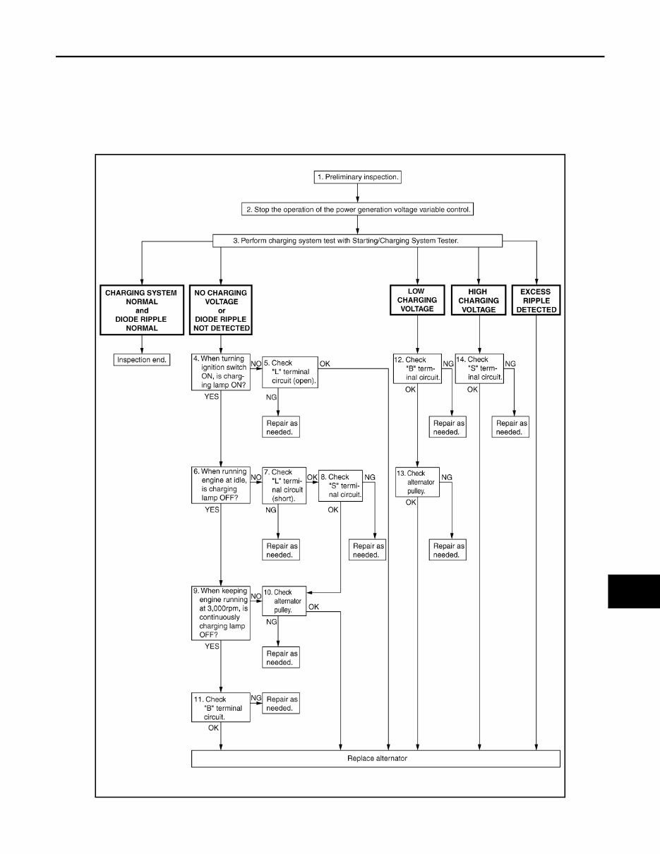
CHG-4 < BASIC INSPECTION > DIAGNOSIS AND REPAIR WORK FLOW NOTE: To ensure a complete and thorough diagnosis, the battery, starter and alternator test segments must be done as a set from start to finish. 1.PRELIMINARY INSPECTION Perform the preliminary inspection. Refer to CHG-20, " Inspection Procedure " . >> GO TO 2. 2.STOP POWER GENERATION VOLTAGE VARIABLE CONTROL SYSTEM Stop the operation of the power generation voltage variable control in either of the following procedures. • After selecting “ENGINE” of “SELECT SYSTEM” using CONSULT, set the DUTY value of “ALTERNATOR DUTY” to 0 % by selecting “ALTERNATOR DUTY” of “Active Test”. Continue “Active Test” until the end of inspection. (When the DUTY value is 0 or 100 %, the normal power generation is performed according to the characteristic of the IC voltage regulator of the alternator.) • Turn the ignition switch OFF, and disconnect the battery current sensor connector. [However, DTC (P1550 - P1554) of the engine might remain. After finishing the inspection, connect the battery current sensor connec- tor and erase the self-diagnosis results history of the engine using CONSULT.] >> GO TO 3. 3.DIAGNOSIS WITH STARTING/CHARGING SYSTEM TESTER Perform the charging system test using Starting/Charging System Tester (SST: J-44373). For details and oper- ating instructions, refer to Technical Service Bulletin. Test result CHARGING SYSTEM NORMAL>>Charging system is normal and will also show “DIODE RIPPLE” test result. NO CHARGING VOLTAGE>>GO TO 4. LOW CHARGING VOLTAGE>>GO TO 12. HIGH CHARGING VOLTAGE>>GO TO 14. DIODE RIPPLE NORMAL>>Diode ripple is OK and will also show “CHARGING VOLTAGE” test result. EXCESS RIPPLE DETECTED>>Replace the alternator. Perform “DIODE RIPPLE” test again using Starting/ Charging System Tester (SST: J-44373) to confirm repair. DIODE RIPPLE NOT DETECTED>>GO TO 4. 4.INSPECTION WITH CHARGE WARNING LAMP (IGNITION SWITCH IS ON) Turn the ignition switch ON. Does the charge warning lamp illuminate? YES >> GO TO 6. NO >> GO TO 5. 5.“L” TERMINAL CIRCUIT (OPEN) INSPECTION Check “L” terminal circuit (open). Refer to CHG-11, " Diagnosis Procedure " . Is the “ L ” terminal circuit normal? YES >> Replace alternator. NO >> Repair as needed. 6.INSPECTION WITH CHARGE WARNING LAMP (IDLING) Start the engine and run it at idle. Does the charge warning lamp turn OFF? YES >> GO TO 9. NO >> GO TO 7. 7.“L” TERMINAL CIRCUIT (SHORT) INSPECTION Check “L” terminal circuit (short). Refer to CHG-13, " Diagnosis Procedure " . Is the “ L ” terminal circuit normal? YES >> GO TO 8. NO >> Repair as needed. Revision: 2011 August 2012 FX35/FX50
CHG DIAGNOSIS AND REPAIR WORK FLOW CHG-5 < BASIC INSPECTION > C D E F G H I J K L B A O P N 8.“S” TERMINAL CIRCUIT INSPECTION Check “S” terminal circuit. Refer to CHG-14, " Diagnosis Procedure " . Is the “ S ” terminal circuit normal? YES >> GO TO 10. NO >> Repair as needed. 9.INSPECTION WITH CHARGE WARNING LAMP (ENGINE AT 3,000 RPM) Increase and maintain the engine speed at 3,000 rpm. Does the charge warning lamp remain off? YES >> GO TO 11. NO >> GO TO 10. 10.INSPECTION OF ALTERNATOR PULLEY Check alternator pulley. Refer to CHG-26, " VQ35HR : Inspection " (VQ35HR) or CHG-28, " VK50VE : Inspec- tion " (VK50VE). Is alternator pulley normal? YES >> Replace alternator. NO >> Repair as needed. 11.“B” TERMINAL CIRCUIT INSPECTION Check “B” terminal circuit. Refer to CHG-10, " Diagnosis Procedure " . Is “ B ” terminal circuit normal? YES >> Replace alternator. NO >> Repair as needed. 12.“B” TERMINAL CIRCUIT INSPECTION Check “B” terminal circuit. Refer to CHG-10, " Diagnosis Procedure " . Is “ B ” terminal circuit normal? YES >> GO TO 13. NO >> Repair as needed. 13.INSPECTION OF ALTERNATOR PULLEY Check alternator pulley. Refer to CHG-26, " VQ35HR : Inspection " (VQ35HR) or CHG-28, " VK50VE : Inspec- tion " (VK50VE). Is alternator pulley normal? YES >> Replace alternator. NO >> Repair as needed. 14.“S” TERMINAL CIRCUIT INSPECTION Check “S” terminal circuit. Refer to CHG-14, " Diagnosis Procedure " . Is the “ S ” terminal circuit normal? YES >> Replace alternator. NO >> Repair as needed. Revision: 2011 August 2012 FX35/FX50
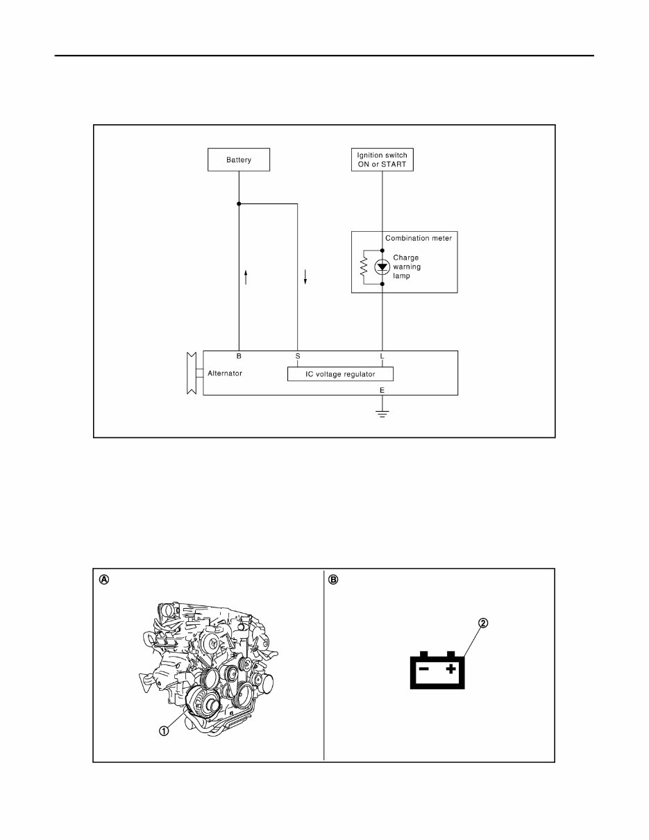
CHG-6 < SYSTEM DESCRIPTION > CHARGING SYSTEM SYSTEM DESCRIPTION CHARGING SYSTEM System Diagram INFOID:0000000007519413 System Description INFOID:0000000007519414 The alternator provides DC voltage to operate the vehicle's electrical system and to keep the battery charged. The voltage output is controlled by the IC voltage regulator. VQ35HR VQ35HR : Component Parts Location INFOID:0000000007519415 JPMIA0426GB 1. Alternator 2. Charge warning lamp A. Cylinder block (bank 1) side B. Combination meter JSMIA0054ZZ Revision: 2011 August 2012 FX35/FX50
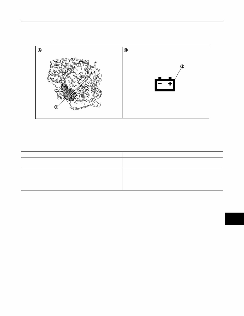
CHG CHARGING SYSTEM CHG-7 < SYSTEM DESCRIPTION > C D E F G H I J K L B A O P N VK50VE VK50VE : Component Parts Location INFOID:0000000007519416 Component Description INFOID:0000000007519417 1. Alternator 2. Charge warning lamp A. Cylinder block (bank 1) side B. Combination meter JSMIA0070ZZ Component part Description Alternator The alternator provides DC voltage to operate the vehicle electri- cal system and to keep the battery charged. Combination meter (Charge warning lamp) The IC voltage regulator warning function activates to illuminate the charge warning lamp, if any of the following symptoms occur while alternator is operating: • Excessive voltage is produced. • No voltage is produced. Revision: 2011 August 2012 FX35/FX50
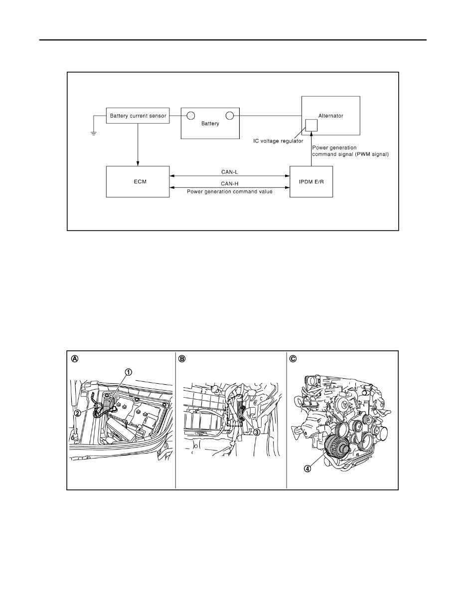
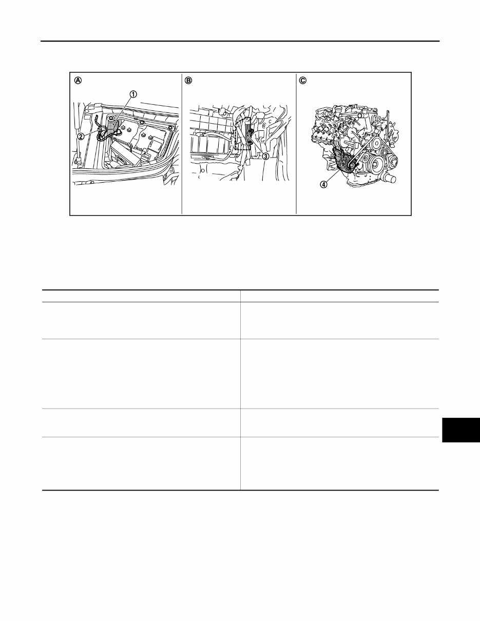
CHG-8 < SYSTEM DESCRIPTION > POWER GENERATION VOLTAGE VARIABLE CONTROL SYSTEM POWER GENERATION VOLTAGE VARIABLE CONTROL SYSTEM System Diagram INFOID:0000000007519418 System Description INFOID:0000000007519419 By performing the power generation voltage variable control, the engine load due to the power generation of the alternator is reduced and fuel consumption is decreased. NOTE: When any malfunction is detected in the power generation voltage variable control system, the power genera- tion is performed according to the characteristic of the IC voltage regulator of the alternator. VQ35HR VQ35HR : Component Parts Location INFOID:0000000007519420 VK50VE JPMIA0632GB 1. IPDM E/R 2. Battery current sensor 3. ECM 4. Alternator A. Engine room dash panel (RH) B. Behind glove box C. Cylinder block (bank 1) side JSMIA0069ZZ Revision: 2011 August 2012 FX35/FX50
CHG POWER GENERATION VOLTAGE VARIABLE CONTROL SYSTEM CHG-9 < SYSTEM DESCRIPTION > C D E F G H I J K L B A O P N VK50VE : Component Parts Location INFOID:0000000007519421 Component Description INFOID:0000000007519422 1. IPDM E/R 2. Battery current sensor 3. ECM 4. Alternator A. Engine room dash panel (RH) B. Behind glove box C. Cylinder block (bank 1) side JSMIA0068ZZ Component part Description Battery current sensor Battery current sensor is installed to the battery cable at the neg- ative terminal, and it detects the charging/discharging current of the battery and sends the voltage signal to ECM according to the current value. ECM Battery current sensor detects the charging/discharging current of the battery. ECM judges the battery condition based on this signal. ECM judges whether to perform the power generation voltage variable control according to the battery condition. When performing the power generation voltage variable control, ECM calculates the target power generation voltage according to the battery condition and sends the calculated value as the power generation command value to IPDM E/R. IPDM E/R IPDM E/R converts the received power generation command val- ue into the power generation command signal (PWM signal) and sends it to the IC voltage regulator. Alternator (IC voltage regulator) IC voltage regulator controls the power generation voltage by the target power generation voltage based on the received power gen- eration command signal. When there is no power generation command signal, the alterna- tor performs the normal power generation according to the char- acteristic of the IC voltage regulator. Revision: 2011 August 2012 FX35/FX50
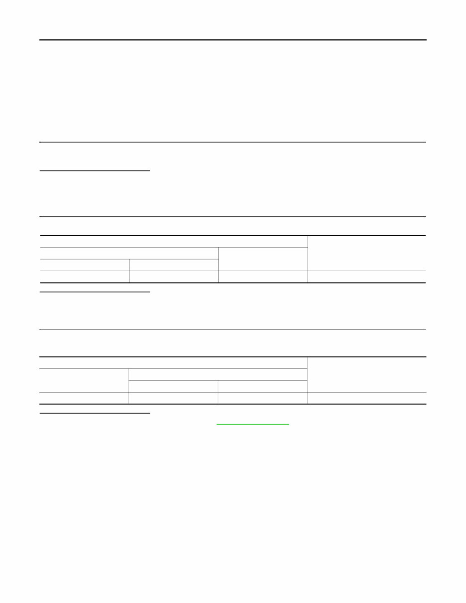
CHG-10 < DTC/CIRCUIT DIAGNOSIS > B TERMINAL CIRCUIT DTC/CIRCUIT DIAGNOSIS B TERMINAL CIRCUIT Description INFOID:0000000007519423 “B” terminal circuit supplies power to charge the battery and to operate the vehicle’s electrical system. Diagnosis Procedure INFOID:0000000007519424 1.CHECK “B” TERMINAL CONNECTION 1. Turn ignition switch OFF. 2. Check if “B” terminal is clean and tight. Is the inspection result normal? YES >> GO TO 2. NO >> Repair “B” terminal connection. Confirm repair by performing complete Starting/Charging system test. Refer to Technical Service Bulletin. 2.CHECK “B” TERMINAL CIRCUIT Check voltage between alternator “B” terminal and ground. Is the inspection result normal? YES >> GO TO 3. NO >> Check harness for open between alternator and fusible link. 3.CHECK “B” TERMINAL CONNECTION (VOLTAGE DROP TEST) 1. Start engine, then engine running at idle and warm. 2. Check voltage between battery positive terminal and alternator “B” terminal. Is the inspection result normal? YES >> “B” terminal circuit is normal. Refer to CHG-3, " Work Flow " . NO >> Check harness between battery and alternator for poor continuity. Terminals Voltage (Approx.) (+) (–) Alternator “B” terminal Terminal E203 1 Ground Battery voltage Terminals Voltage (Approx.) (+) (–) Alternator “B” terminal Terminal Battery positive terminal E203 1 Less than 0.2 V Revision: 2011 August 2012 FX35/FX50
If you are in need of a repair manual for your 2012 Infiniti FX35, look no further. This accessible repair manual is perfect for both professional mechanics and DIY enthusiasts. In the past, traditional service manuals in book format were costly and inconvenient. Now, you can access the same information in a more affordable and convenient digital format.
Whether you need to fix the brakes, replace suspension components, address engine issues, or perform standard maintenance, this repair manual has you covered. It contains comprehensive service information for the brakes, engine, suspension, steering, drivetrain, electrical systems, heating, air conditioning, and more.
By utilizing this repair manual, you can save a significant amount of money on vehicle maintenance. Mechanics often charge high fees for their services, making DIY repairs a cost-effective alternative. This 2012 Infiniti FX35 repair manual is compatible with Windows, Mac computers, smartphones, and tablets, ensuring ease of use for all users.