LT-1 ELECTRICAL C D E F G H I J L M SECTION LT A B LT N O P CONTENTS LIGHTING SYSTEM SERVICE INFORMATION ........................... 4 PRECAUTIONS .................................................. 4 Precaution for Supplemental Restraint System (SRS) "AIR BAG" and "SEAT BELT PRE-TEN- SIONER" .................................................................. 4 General Precaution for Service Operation ............... 4 HEADLAMP - XENON TYPE - ........................... 5 Component Parts and Harness Connector Loca- tion ........................................................................... 5 System Description .................................................. 5 CAN Communication System Description ................ 7 CAN Communication Unit ........................................ 7 Schematic ................................................................ 8 Wiring Diagram - H/LAMP - ...................................... 9 Terminal and Reference Value for BCM ................ 12 Terminal and Reference Value for IPDM E/R ........ 14 How to Proceed with Trouble Diagnosis ................ 14 Preliminary Check .................................................. 15 CONSULT-III Functions (BCM) .............................. 16 CONSULT-III Functions (IPDM E/R) ...................... 17 Headlamp Does Not Change To High Beam (Both Sides) ..................................................................... 18 Headlamp Does Not Change To High Beam (One Side) ....................................................................... 20 Headlamp Low Beam Does Not Illuminate (Both Sides) ..................................................................... 21 Headlamp Low Beam Does Not Illuminate (One Side) ....................................................................... 23 Headlamp RH Low Beam and High Beam Does Not Illuminate ......................................................... 24 Headlamp LH Low Beam and High Beam Does Not Illuminate ......................................................... 25 Headlamps Does Not Turn OFF ............................ 26 General Information for Xenon Headlamp Trouble Diagnosis ............................................................... 26 Caution: .................................................................. 26 Xenon Headlamp Trouble Diagnosis ..................... 27 Aiming Adjustment ................................................. 27 Bulb Replacement .................................................. 28 Removal and Installation ........................................30 Disassembly and Assembly ....................................30 DAYTIME LIGHT SYSTEM ............................... 32 Component Parts and Harness Connector Loca- tion ..........................................................................32 System Description .................................................32 CAN Communication System Description ..............33 CAN Communication Unit .......................................33 Schematic ...............................................................34 Wiring Diagram - DTRL - ........................................35 Terminal and Reference Value for BCM .................38 How to Proceed with Trouble Diagnosis .................41 Preliminary Check ..................................................41 CONSULT-III Functions (BCM) ..............................43 Daytime Light Control Does Not Operate Properly ....44 Aiming Adjustment ..................................................46 Bulb Replacement ..................................................46 Removal and Installation ........................................46 Disassembly and Assembly ....................................46 AUTO LIGHT SYSTEM ..................................... 47 Component Parts and Harness Connector Loca- tion ..........................................................................47 System Description .................................................47 CAN Communication System Description ..............48 CAN Communication Unit .......................................48 Major Component and Functions ...........................48 Schematic ...............................................................49 Wiring Diagram - AUTO/L - ....................................50 Terminal and Reference Value for BCM .................52 Terminal and Reference Value for IPDM E/R .........54 How to Proceed with Trouble Diagnosis .................54 Preliminary Check ..................................................55 CONSULT-III Functions (BCM) ..............................56 CONSULT-III Functions (IPDM E/R) ......................57 Symptom Chart .......................................................58 Lighting Switch Inspection ......................................58 Optical sensor System Inspection ..........................59 Removal and Installation of Optical Sensor ............60 Revision: 2007 April 2008 FX35/FX45
LT-2 HEADLAMP AIMING CONTROL ..................... 61 Schematic .............................................................. 61 Wiring Diagram - H/AIM - ...................................... 62 Removal and Installation ....................................... 64 Switch Circuit Inspection ....................................... 65 FRONT FOG LAMP .......................................... 66 Component Parts and Harness Connector Loca- tion ......................................................................... 66 System Description ................................................ 66 CAN Communication System Description ............. 67 CAN Communication Unit ...................................... 67 Wiring Diagram - F/FOG - ..................................... 68 Terminal and Reference Value for BCM ................ 69 Terminal and Reference Value for IPDM E/R ........ 70 How to Proceed with Trouble Diagnosis ................ 71 Preliminary Check ................................................. 71 CONSULT-III Functions (BCM) ............................. 72 CONSULT-III Functions (IPDM E/R) ..................... 72 Front Fog Lamps Do Not Illuminate (Both Sides) ... 72 Front Fog Lamp Does Not Illuminate (One Side) ... 74 Aiming Adjustment ................................................. 75 Bulb Replacement ................................................. 76 Removal and Installation ....................................... 76 TURN SIGNAL AND HAZARD WARNING LAMPS .............................................................. 78 Component Parts and Harness Connector Loca- tion ......................................................................... 78 System Description ................................................ 78 CAN Communication System Description ............. 80 CAN Communication Unit ...................................... 80 Schematic .............................................................. 81 Wiring Diagram - TURN - ....................................... 82 Terminal and Reference Value for BCM ................ 84 Terminal and Reference Value for Rear Combina- tion Lamp Control Unit ........................................... 86 How to Proceed with Trouble Diagnosis ................ 88 Preliminary Check ................................................. 88 CONSULT-III Functions (BCM) ............................. 89 Turn Signal Lamp Does Not Operate .................... 90 Rear Turn Signal Lamp Does Not Operate ........... 92 Hazard Warning Lamp Does Not Operate But Turn Signal Lamp Operates .................................. 94 Bulb Replacement (Front Turn Signal Lamp) ........ 95 Bulb Replacement (Rear Turn Signal Lamp) ......... 95 Removal and Installation of Front Turn Signal Lamp ...................................................................... 95 Removal and Installation of Rear Turn Signal Lamp ...................................................................... 95 Removal and Installation of Rear Combination Lamp Control Unit .................................................. 95 LIGHTING AND TURN SIGNAL SWITCH ........ 96 Removal and Installation ....................................... 96 HAZARD SWITCH ............................................ 97 Removal and Installation ....................................... 97 COMBINATION SWITCH ................................. 98 Wiring Diagram - COMBSW - ................................ 98 Combination Switch Reading Function .................. 98 Terminal and Reference Value for BCM ................ 99 CONSULT-III Functions (BCM) ............................ 103 Combination Switch Inspection ............................ 104 Removal and Installation ...................................... 107 STOP LAMP .................................................... 108 Component Parts and Harness Connector Loca- tion ....................................................................... 108 System Description .............................................. 108 Schematic ............................................................ 109 Wiring Diagram - STOP/L - .................................. 110 Terminal and Reference Value for Rear Combina- tion Lamp Control Unit ......................................... 112 Stop Lamp Does Not Operate .............................. 112 High-Mounted Stop Lamp .................................... 114 Stop Lamp ............................................................ 115 Rear Combination Lamp Control Unit .................. 115 BACK-UP LAMP ............................................. 116 Wiring Diagram - BACK/L - .................................. 116 Bulb Replacement ................................................ 117 Removal and Installation ...................................... 117 PARKING, LICENSE PLATE AND TAIL LAMPS ............................................................. 118 Component Parts and Harness Connector Loca- tion ....................................................................... 118 System Description .............................................. 118 CAN Communication System Description ........... 120 CAN Communication Unit .................................... 120 Schematic ............................................................ 121 Wiring Diagram - TAIL/L - .................................... 122 Terminal and Reference Value for BCM .............. 126 Terminal and Reference Value for IPDM E/R ...... 127 Terminal and Reference Value for Rear Combina- tion Lamp Control Unit ......................................... 128 How to Proceed with Trouble Diagnosis .............. 128 Preliminary Check ................................................ 128 CONSULT-III Functions (BCM) ............................ 129 CONSULT-III Functions (IPDM E/R) .................... 129 Parking, License Plate and Side Marker Lamps Do Not Illuminate ................................................. 129 Tail Lamp Does Not Operate ............................... 133 Parking, License Plate, Side Maker and Tail Lamps Do Not Turn OFF (After Approx. 10 Min- utes) ..................................................................... 134 License Plate Lamp ............................................. 135 Front Parking Lamp ............................................. 135 Tail Lamp ............................................................. 135 Front Side Marker Lamp ...................................... 135 Rear Side Marker Lamp ....................................... 136 Rear Combination Lamp Control Unit .................. 136 REAR COMBINATION LAMP ......................... 137 Bulb Replacement ................................................ 137 Removal and Installation ...................................... 137 INTERIOR ROOM LAMP ................................. 138 Revision: 2007 April 2008 FX35/FX45
LT-3 C D E F G H I J L M A B LT N O P Component Parts and Harness Connector Loca- tion ....................................................................... 138 System Description .............................................. 138 Schematic ............................................................ 143 Wiring Diagram - ROOM/L - ................................. 145 Terminal and Reference Value for BCM .............. 153 How to Proceed with Trouble Diagnosis .............. 154 Preliminary Check ................................................ 154 CONSULT-III Functions (BCM) ............................ 155 Interior Room Lamp Control Does Not Operate ... 157 Map Lamp Control Does Not Operate .................. 158 Personal Lamp Control Does Not Operate .......... 160 Ignition Keyhole Illumination Control Does Not Operate ................................................................ 161 All Step Lamps Do Not Operate ........................... 162 All Interior Room Lamps Do Not Operate ............ 164 Bulb Replacement ................................................ 164 Removal and Installation ...................................... 166 ILLUMINATION ............................................... 169 System Description ............................................... 169 CAN Communication System Description ............ 170 CAN Communication Unit ..................................... 170 Schematic ............................................................. 171 Wiring Diagram - ILL - .......................................... 173 Bulb Replacement ................................................ 181 Removal and Installation ...................................... 182 BULB SPECIFICATIONS ................................ 183 Headlamp ............................................................. 183 Exterior Lamp ....................................................... 183 Interior Lamp/Illumination ..................................... 183 Revision: 2007 April 2008 FX35/FX45
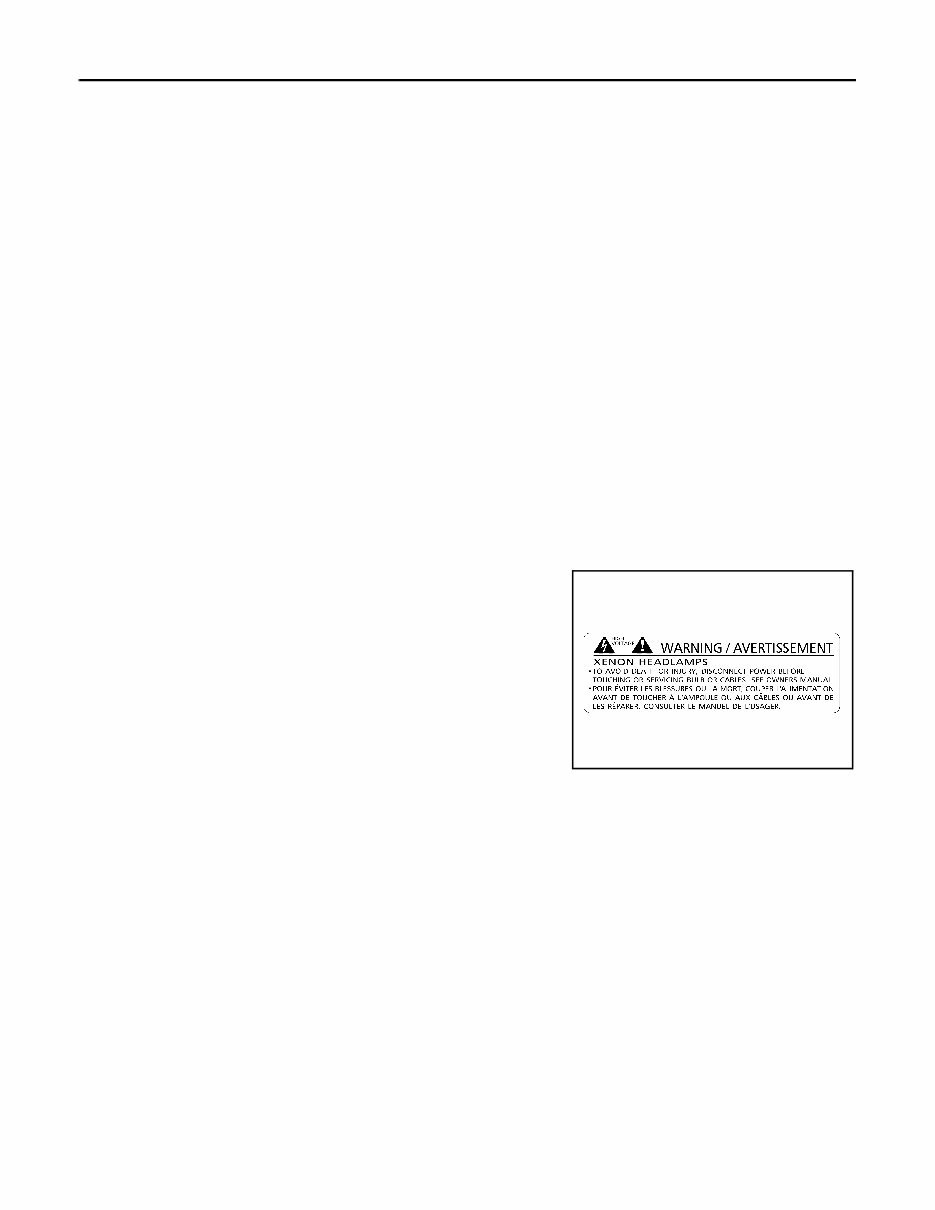
LT-4 < SERVICE INFORMATION > PRECAUTIONS SERVICE INFORMATION PRECAUTIONS Precaution for Supplemental Restraint System (SRS) "AIR BAG" and "SEAT BELT PRE-TENSIONER" INFOID:0000000001612924 The Supplemental Restraint System such as “AIR BAG” and “SEAT BELT PRE-TENSIONER”, used along with a front seat belt, helps to reduce the risk or severity of injury to the driver and front passenger for certain types of collision. This system includes seat belt switch inputs and dual stage front air bag modules. The SRS system uses the seat belt switches to determine the front air bag deployment, and may only deploy one front air bag, depending on the severity of a collision and whether the front occupants are belted or unbelted. Information necessary to service the system safely is included in the “SUPPLEMENTAL RESTRAINT SYS- TEM” and “SEAT BELTS” of this Service Manual. WARNING: • To avoid rendering the SRS inoperative, which could increase the risk of personal injury or death in the event of a collision which would result in air bag inflation, all maintenance must be performed by an authorized NISSAN/INFINITI dealer. • Improper maintenance, including incorrect removal and installation of the SRS, can lead to personal injury caused by unintentional activation of the system. For removal of Spiral Cable and Air Bag Module, see the “SUPPLEMENTAL RESTRAINT SYSTEM”. • Do not use electrical test equipment on any circuit related to the SRS unless instructed to in this Service Manual. SRS wiring harnesses can be identified by yellow and/or orange harnesses or har- ness connectors. General Precaution for Service Operation INFOID:0000000001328264 • Never work with wet hands. • Xenon headlamp includes high voltage generating part. Be sure to disconnect battery negative cable (negative terminal) or power fuse before removing, installing, or touching the xenon headlamp (including lamp bulb). • Turn the lighting switch OFF before disconnecting and connecting the connector. • When turning the xenon headlamp on and while it is illuminated, never touch the harness, bulb, and socket of the headlamp. • When checking the headlamp on/off operation, check it on vehicle and with the power connected to the vehicle-side connector. • Do not touch the headlamp bulb glass surface with bare hands or allow oil or grease to get on it. Do not touch the headlamp bulb just after the headlamp is turned off, because it is very hot. • Install the xenon headlamp bulb socket correctly. If it is installed improperly, high-voltage leak or corona dis- charge may occur that can melt the bulb, connector, and housing. Do not illuminate the xenon headlamp bulb out of the headlamp housing. Doing so can cause fire and harm your eyes. • When the bulb has burned out, wrap it in a thick vinyl bag and discard. Do not break the bulb. • Leaving the bulb removed from the headlamp housing for a long period of time can deteriorate the perfor- mance of the lens and reflector (dirt, clouding). Always prepare a new bulb and have it on hand when replac- ing the bulb. • When adjusting the headlamp aiming, turn the aiming adjustment screw only in the tightening direction. (If it is necessary to loosen the screw, first fully loosen the screw, and then turn it in the tightening direction.) • Do not use organic solvent (paint thinner or gasoline) to clean lamps and to remove old sealant. PKID0793E Revision: 2007 April 2008 FX35/FX45
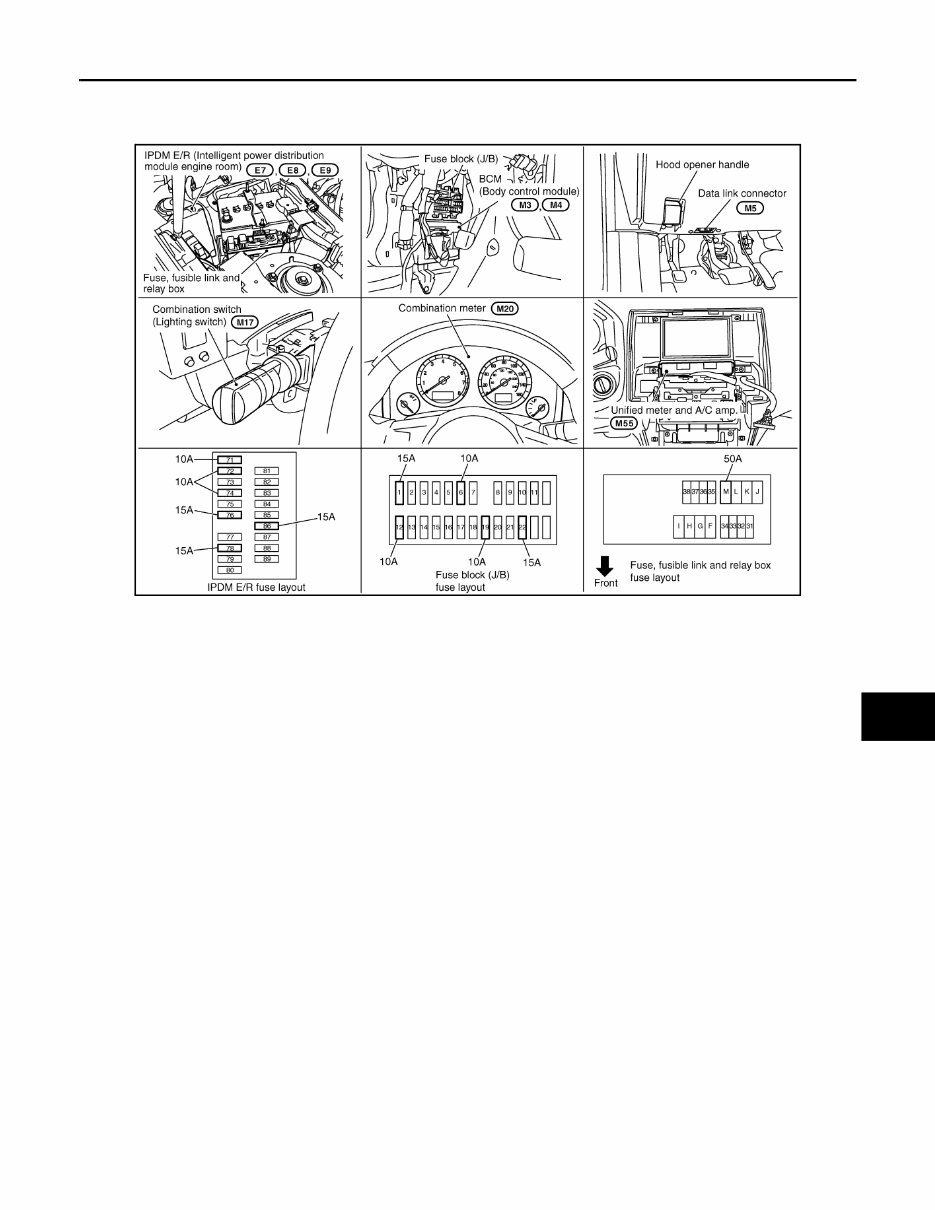
HEADLAMP - XENON TYPE - LT-5 < SERVICE INFORMATION > C D E F G H I J L M A B LT N O P HEADLAMP - XENON TYPE - Component Parts and Harness Connector Location INFOID:0000000001328265 System Description INFOID:0000000001328266 Control of the headlamp system operation is dependent upon the position of the combination switch (lighting switch). When the lighting switch is placed in the 2ND position, the BCM (body control module) receives input signal requesting the headlamps (and tail lamps) illuminate. This input signal is communicated to the IPDM E/ R (intelligent power distribution module engine room) through the CAN communication lines. The CPU (central processing unit) located in the IPDM E/R controls the headlamp high and headlamp low relay coils. These relays, when energized, direct power to the respective headlamps, which then illuminate. If voltage is applied to a high beam solenoid, the bulb shade will move, even a xenon head lamp bulb comes out, and a high beam and a low beam are changed. OUTLINE Power is supplied at all times • to headlamp high relay, located in IPDM E/R • to headlamp low relay, located in IPDM E/R and • to ignition relay, located in IPDM E/R, from battery direct, • through 10A fuse (No. 71, located in IPDM E/R) • to CPU located in IPDM E/R, • through 15A fuse (No. 78, located in IPDM E/R) • to CPU located in IPDM E/R, • through 50A fusible link (letter M, located in fuse, fusible link and relay box) • to BCM terminal 55, • through 15A fuse [No. 22, located in fuse block (J/B)] • to BCM terminal 42, • through 10A fuse [No. 19, located in fuse block (J/B)] • to combination meter terminal 8. With ignition switch in ON or START position, power is supplied • to ignition relay, located in IPDM E/R, from battery direct • through 15A fuse [No. 1, located in fuse block (J/B)] • to BCM terminal 38, • through 10A fuse [No. 14, located in fuse block (J/B)] PKIC9683E Revision: 2007 April 2008 FX35/FX45
You're Reading a Preview
What's Included?
Lifetime Access
Fast Download Speeds
Offline Viewing
Access Contents & Bookmarks
Full Search Facility
Print one or all pages of your manual
$36.99
2008 Infiniti FX35 Service & Repair Manual Software
If you are in need of a repair manual for your 2008 Infiniti FX35, look no further. Our comprehensive repair manual software is the perfect solution for both professional mechanics and DIY enthusiasts. Unlike traditional paper manuals, this accessible software provides a more cost-effective and convenient way to access the necessary information.
Whether you are looking to address brake issues, replace suspension components, troubleshoot engine problems, or perform standard maintenance, this repair manual software has you covered. It contains all the service information required to tackle various aspects of your vehicle, including brakes, engine, suspension, steering, drivetrain, electrical systems, heating, and air conditioning.
By utilizing this software, you can save a significant amount of money on repairs, as professional mechanics often charge high fees for their services. The 2008 Infiniti FX35 repair manual software is designed to be user-friendly and is compatible with Windows, Mac computers, smartphones, and tablets, ensuring easy access for all users.
Reviews
Q&A
Recently Viewed
5,521,897Happy Clients
2,594,462eManuals
1,120,453Trusted Sellers
15Years in Business
Price:
Actual Price:
2008 Infiniti FX35 Service & Repair Manual Software





 Lifetime Access




