


NEXO(FE) > 2022 > Body Repair > Body Repair Manual
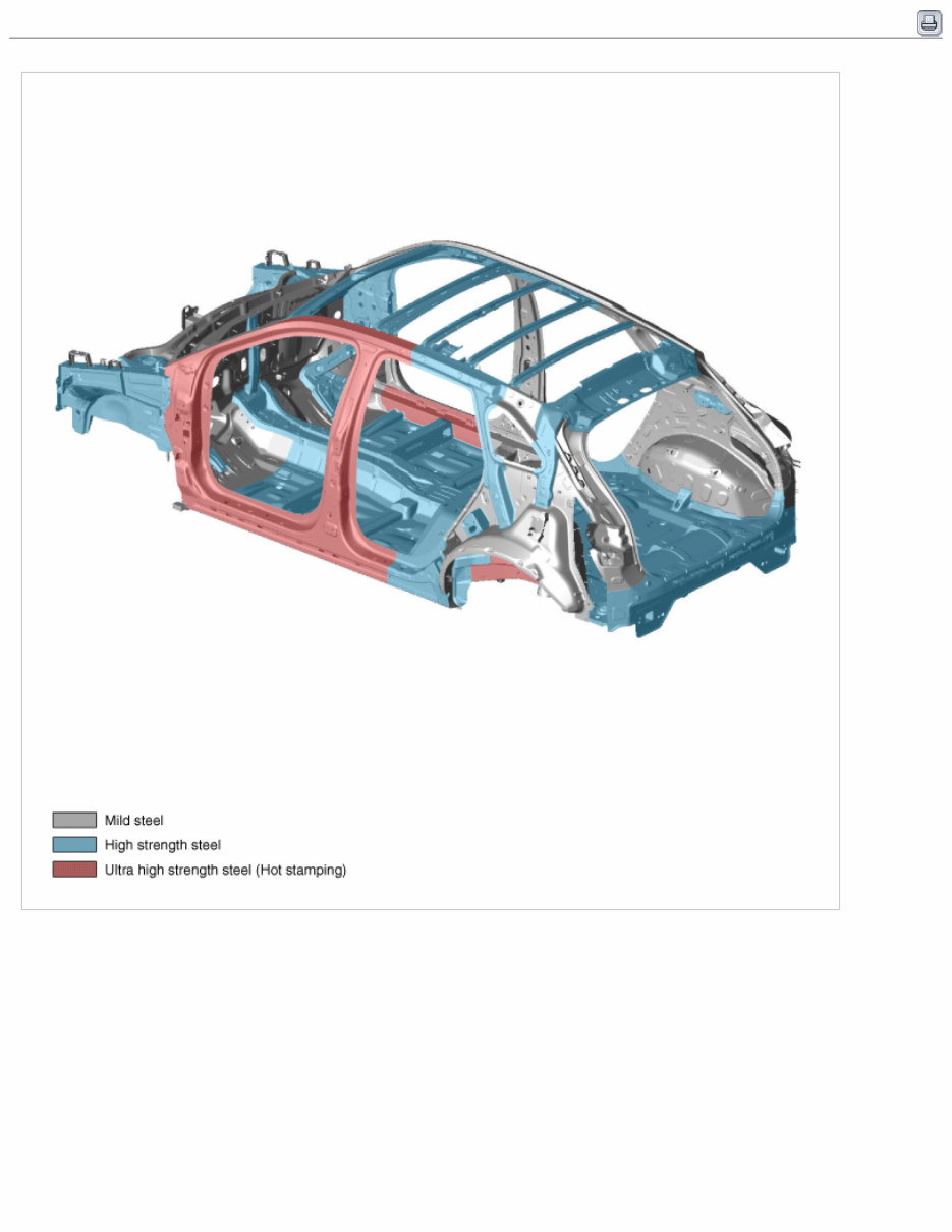
- Upper Body
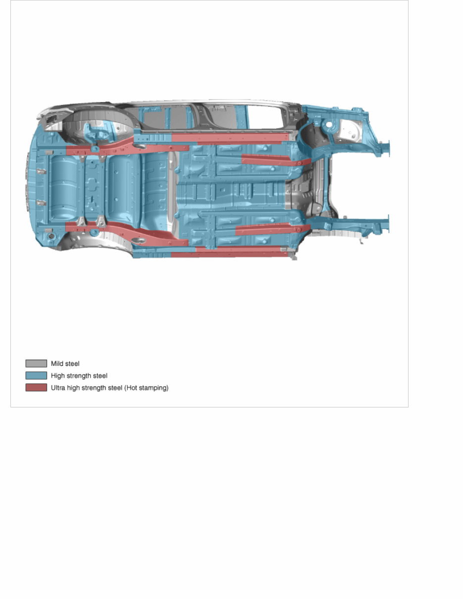
- Under Body
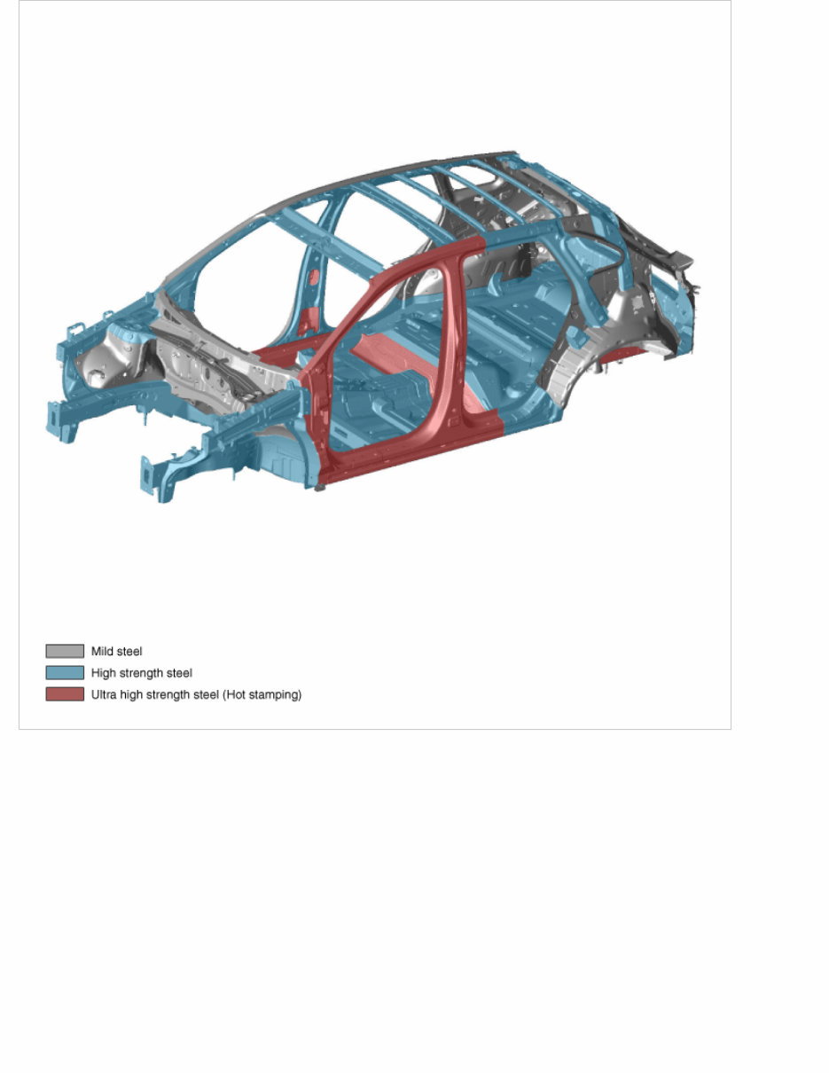
- Interior

NEXO(FE) > 2022 > Body Repair > Body Repair Manual
- General Safety Information and Caution
The Tucson Hydrogen Fuel Cell vehicle operates on approximately 180 - 400 volts DC and uses high pressure hydrogen
gas as a fuel source. Be sure to follow safety instructions below. Failure to follow safety instructions may result in
serious injury or electrocution.
[Safety precaution for Hydrogen system]
Hydrogen Gas Features
Hydrogen is a unique gaseous element that possesses the lowest molecular weight of any gas.
It is colorless, odorless, tasteless, non-corrosive, flammable and highly volatile.
Hydrogen is a combustible fuel. Therefore, some precautions must be taken when performing service on a hydrogen fuel
cell vehicle.
However, it is no more dangerous and it is rather less dangerous than other commonly used fuels in some respects.
Hydrogen has much lower density which gives it a comparative advantage from a safety point of view.
Owing to this, hydrogen gas tends not to mix with air and disperses upwards in the air.
This means that the concentration levels of hydrogen necessary for ignition or detonation are unlikely to be achieved.
Hydrogen is a very small molecule with low viscosity, and therefore prone to leakage. Proper ventilation and the
use of hydrogen detection sensors can help to mitigate some of the hazards associated with gaseous hydrogen.
The followings are properties of gaseous hydrogen.
• It has the lowest molecular weight, and has the smallest molecules of any elements.
• It has the lowest density and the highest buoyancy of any element.
• It can cause brittleness in some materials, including metals (but materials chosen for hydrogen applications are
not susceptible to brittleness).
• It is colorless, odorless and tasteless.
• It burns invisibly and without smoke.
• It has the lowest ignition energy of any fuel (less than one-tenth that of other fuels).
• It has a wide flammability concentration range of 4% to 75%
When servicing the hydrogen storage and supply system, pay attention to the following items.
• Clean all work shop and surrounding areas before removing the part.
• Place removed parts on a clean cover and surface.
• Use lint-free cloths only.
• Carefully cover or seal opened parts with a tape if repairs cannot be carried out immediately.
• Install clean components only.
• Defined regulations for hydrogen system service may vary with countries.
Therefore all service and maintenance instructions are based on local country requirements safety regulations.
• The Tucson Hydrogen Fuel Cell vehicle must be repaired in authorized workshops that are equipped with
proper ventilation and a hydrogen detection system.
• There must be no ignition sources around the vehicle.
For example, any exposed flames, sparks, electrostatic discharge, or hot surfaces that could cause hydrogen gas
to ignite must be kept away from the vehicle.

When servicing parts related to the hydrogen supply system, adhere to the following requirements:
1) When leaking the hydrogen gas, make sure there is no source of ignition near the leakage path.
2) Always empty the hydrogen tank according to the following safety guideline.
3) As the system is applied with pressure, gas leak may lead to dangerous situation and injury.
4) The hydrogen tank is fueled with the high pressure hydrogen gas. Make sure to empty the hydrogen tank before
removing it.
5) Do not disassemble the hydrogen tank and solenoid valve even when the tank is empty.
Random disassembling of the hydrogen tank may cause fire and explosion.
6) Clear the combustible substances around the vehicle before the inspection.
7) Completely remove the remaining fuel gas in the fuel line before inspecting the hydrogen storage system.
(Refer to Hydrogen Storage System – Repair procedures – “Residual fuel pressure release procedure”)
8) When removing the hydrogen storage and supply system, do not work with the compressed air as much as
possible.
9) Before removing the hydrogen system, cover the connection part with the cloth. Then, carefully remove the
component.
10) When inspecting the component related to the hydrogen storage system, make sure to use hand tools in order
to prevent any fire due to spark from the electrically driven tools.
• Caution labels are attached to the hydrogen storage system components. The hydrogen storage system is
composed of three cylinders which are filled with Hydrogen gas. The hydrogen tank is made of the high density
plastic material with excellent gas barrier properties against hydrogen gas and carbon fiber composite material
which is capable of withstanding the high pressure. Each tank contains flammable gas under high pressure.
Serious injury or death can result from improper installation, lack of maintenance or overfilling. Do not attempt
to remove the hydrogen storage tanks or any of its fittings from this vehicle. They may contain residual gases
under pressure, which could cause fire or explosion.
• Removal and disposal shall only be done by a qualified technician. Installation of this cylinder must be done in
accordance with the manufacturer’s instruction and local regulation.
• Hydrogen storage components : Hydrogen Management Unit (HMU), Hydrogen Sensor, Hydrogen Tank,
Hydrogen Tank Solenoid Valve Assembly, Hydrogen Tank Purge Valve, Filling Receptacle Assembly, High
Pressure Regulator, Check Valve, etc
[Safety precaution for High voltage system]
• Warning labels for high voltage are attached to the high voltage components. The color of the high voltage
cables and connectors are orange. Do not touch any of these high voltage components, cables, and connectors
without proper Personal Protection Equipment (PPE).
• High voltage components : Fuel cell stack assembly, Fuel cell Control Unit (FCU), Air Blower, COD Heater,
High voltage Junction Box, High Voltage Battery Pack Assembly, Power Relay Assembly (PRA), BMS ECU,
Drive Motor, Electric A/C Compressor, High voltage DC/DC Converter (HDC), Low DC/DC Converter (LDC),
Power Cable, etc.
• Use Mega Ohm Tester when measuring insulation resistance of the high voltage system.
Specification :
High impedance Digital Volt / Ohm Meter
Leads and Meter rated to 1,000 voltage.
• For your safety when servicing the Fuel Cell Electric Vehicle (FCEV):
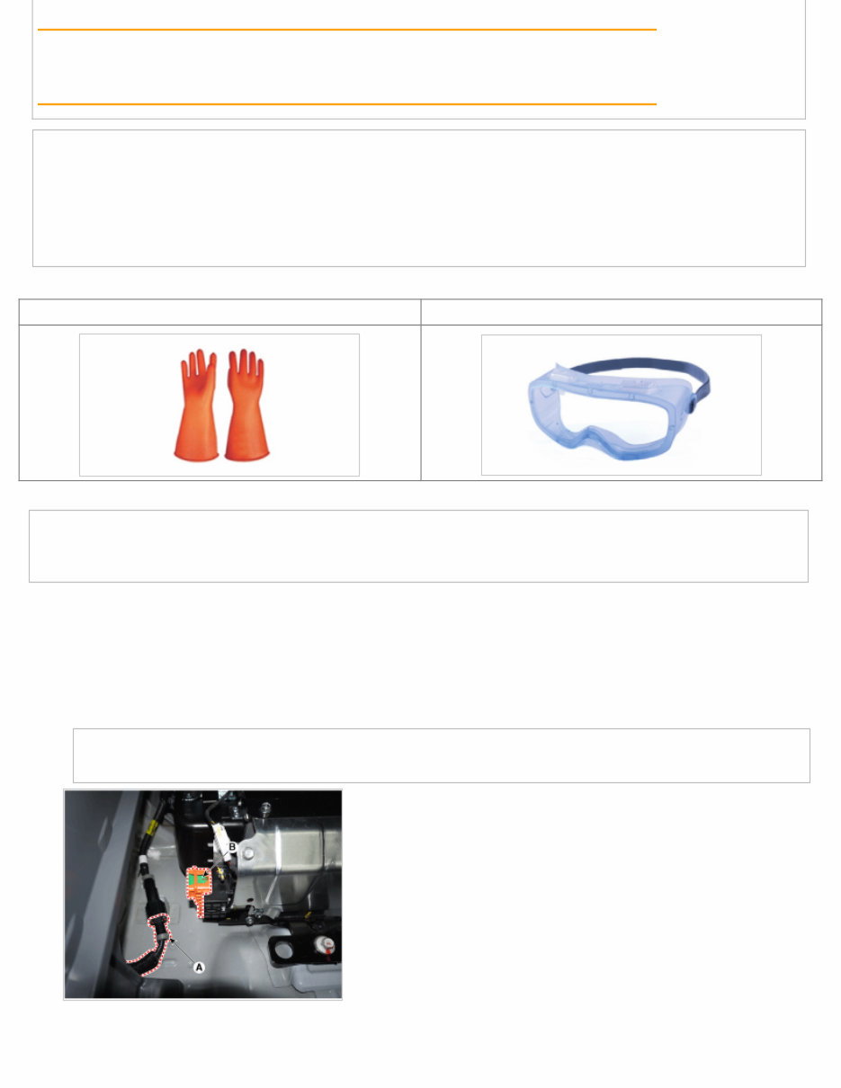
– Wear Personal Protection Equipment (Insulation Gloves and Safety Glasses)
– Do not carry any metallic object (watch, ring etc.) which can cause short circuit.
– Use insulated tools
• Before wearing the protective gear, make sure that they are not torn or broken and free of moisture.
Insulating Gloves Safety Glasses
• Before repair work for any Fuel cell, High voltage, Hydrogen system component, be sure to perform the
procedures as below.
1. Start the fuel cell system by pressing the power button.
2. Check the hydrogen gas leak detection lamp on the cluster.
3. Shut off the high voltage circuit shown in the procedures below.
(Refer to "High Voltage Shut off Procedure" for more detailed procedures.)
(1) Turn the fuel cell system off and disconnect the auxiliary 12V battery negative (-) cable (A).
(2) Remove the safety plug (B).
• Starting the fuel cell system with the safety plug removed may damage the fuel cell control system.
(3) Wait for more than 5 minutes so that the capacitor in the high voltage system can be naturally discharged.
(4) Measure the voltage between the inverter positive and negative power cable terminals to check for inverter
discharge.

(1) Remove the high voltage junction box cover.
(2) Measure the voltage between the inverter positive and negative bus bar terminals to check for capacity
discharge.
Below 30V : High voltage circuit properly shut
More than 30V : High voltage circuit faulty
• Re-check by removing the safety plug, if the voltage is measured over 30V.
• If the voltage is over 30V even though the safety plug is removed, a serious problem will occur in the
high voltage circuit. In this case, perform the DTC diagnosis and do not do any work associated with
the high voltage system.
(5) Remove the high voltage junction box cover. And measure the voltage between the positive and negative bus bar
terminals to check the shut off of the fuel cell.
Below 5V : Fuel cell system circuit properly shut
More than 5V : Fuel cell system circuit faulty
• Re-measure the voltage after 10 minutes, if the voltage is measured over 5V.
• If the voltage is over 5V again, a serious problem will occur in the fuel cell system circuit.
• In this case, perform the DTC diagnosis and do not do any work associated with the fuel cell system.
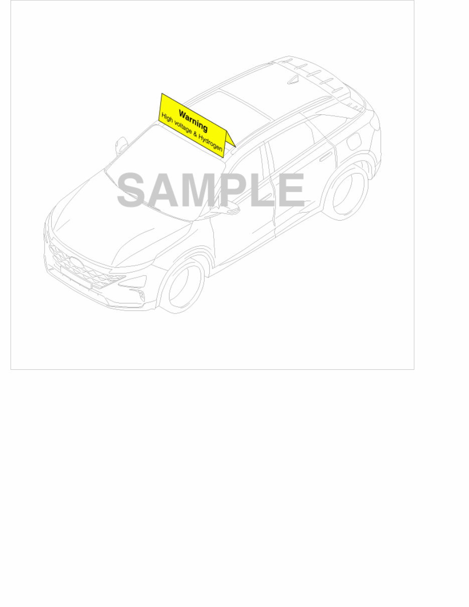
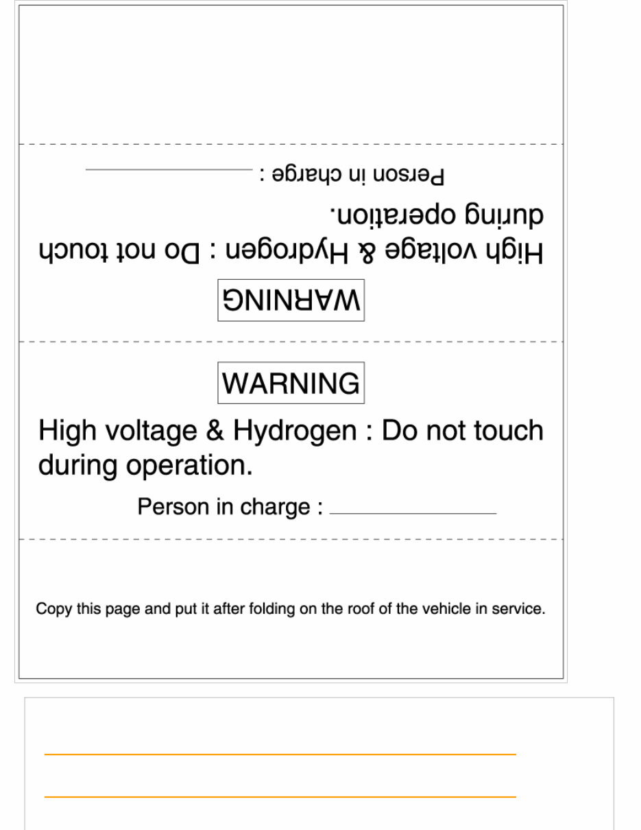
• Attach the 'High Voltage Caution Car Topper' to the vehicle roof to inform other people of the danger of high
voltage.
Be sure to follow instructions below when repairing the high voltage cable.
• Check the voltage of the high voltage connector, terminal or bus bar before repairing.
Below 30V : High voltage circuit properly shut
More than 30V : High voltage circuit faulty
• Be careful not to short circuit between positive (+) and negative (-) terminals.
• Insulate the high voltage connector or terminal with an insulation tape after disconnecting.
• Tighten the high voltage terminal with the specified torque.
• The high voltage battery must be always handled horizontally during repairing or storage. Otherwise, battery
performance may decline or its life may shorten.
• Exposing the high voltage battery to intense heat may cause deterioration.
• Do not bake over 70°C (158°F) / 30 min or 80°C (176°F) / 20 min when painting.
Fuel Cell Electric Vehicle Refrigerant Recovery / Charging Precautions
• Since the electric compressor uses high-voltage, you should use POE oil which has high Volumetric Resistivity.
• Do not use the same A/C recovery / charging equipment as conventional belt-driven compressors.
• If the POE oil of the system gets mixed with PAG oil, then dielectric breakdown due to decreased volumetric
resistivity can deteriorate A/C compressor performance or it may not work.
Air Processing System, Thermal Management System and Fuel Processing System Repairing Precautions
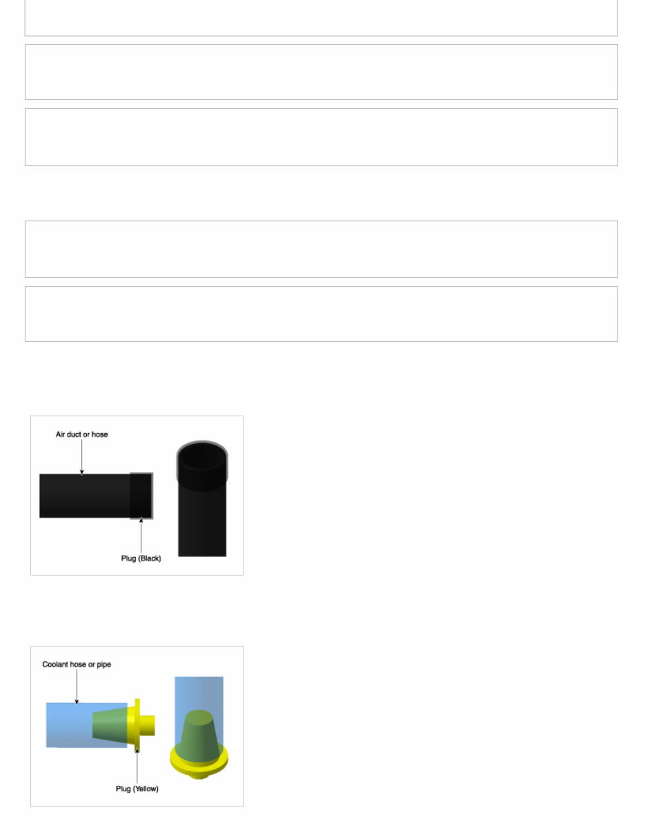
• Air Ducts and Hoses
- To protect fuel cell system, block the open end of the air ducts and hoses using the plugs (09356-4W170).
• Coolant Hoses and Pipes
- To prevent technicians coming in contact with coolant and protect electrical systems, block the open end of the
coolant hoses and pipes using the plugs (09356-4W170).
Stack Cooling System
Motor Cooling System
You're Reading a Preview
What's Included?
 Lifetime Access
Fast Download Speeds
Online & Offline Access
Access PDF Contents & Bookmarks
Full Search Facility
Print one or all pages of your manual
$57.99
2022 Hyundai NEXO (FE) 113KW Service & Repair Manual
Viewed 72 Times Today

What's Included?
Lifetime Access
Fast Download Speeds
Online & Offline Access
Access PDF Contents & Bookmarks
Full Search Facility
Print one or all pages of your manual
$57.99

Secure transaction
What's Included?
Lifetime Access
Fast Download Speeds
Online & Offline Access
Access PDF Contents & Bookmarks
Full Search Facility
Print one or all pages of your manual
Description
The 2022 Hyundai NEXO (FE) 113KW Service & Repair Manual is a comprehensive technical guide designed for professionals and DIY enthusiasts alike. This manual provides detailed information on the maintenance, troubleshooting, and repair of the Hyundai NEXO (FE) 113KW.
- Provides in-depth knowledge on the vehicle's mechanics, allowing users to conduct complex maintenance and repairs
- Includes detailed diagrams, specifications, and step-by-step procedures for troubleshooting and repair
- Suitable for professional mechanics, technicians, and DIY enthusiasts who need technical guidance to maintain and repair their Hyundai NEXO (FE) 113KW
- Covers general information, troubleshooting, and repair procedures for various components and systems
- Helps users to understand and address the inner workings of their vehicle, ensuring they can keep it in good working condition


