

1995-2007 Hummer H1 Service & Repair Manual
What's Included?
Fast Download Speeds
Offline Viewing
Access Contents & Bookmarks
Full Search Facility
Print one or all pages of your manual
2001
SERVICE
MANUAL
COMMERCIAL
HUMMER
®
AM GENERAL CORPORATION
408 South Byrkit Avenue
P.O. Box 728
Mishawaka, Indiana 46546-0728
AM General Number 5745279
Copyright
©
2000
All Rights Reserved. Printed in U.S.A.
TABLE OF CONTENTS
General Information 1
Engine 2
Fuel, Emissions and Exhaust 3
Cooling System 4
Transmission/Transfer Case 5
Wheels and Tires/
Central Tire Inflation System
6
Brake System 7
Steering System 8
Axles/Suspension and Frame 9
Body 10
Heating/Ventilation/
Air Conditioning (HVAC)
11
Electrical 12
Accessories 13
Index 14

________________________________________________________________________________
1-1
®
5745279
Section 1
General Information, Lubrication and Maintenance
TABLE OF CONTENTS
Abbreviations . . . . . . . . . . . . . . . . . . . . . . . . . . . . . . . . . . . . . . . . 1-12
About This Manual . . . . . . . . . . . . . . . . . . . . . . . . . . . . . . . . . . . . . 1-2
Bolt Identification and Torque Limits (Dry*) . . . . . . . . . . . . . . . 1-13
Bolt Identification and Torque Limits (Wet*) . . . . . . . . . . . . . . . 1-14
Carbon Monoxide . . . . . . . . . . . . . . . . . . . . . . . . . . . . . . . . . . . . . 1-2
Component Data . . . . . . . . . . . . . . . . . . . . . . . . . . . . . . . . . . . . . . 1-7
Emission Control information Label . . . . . . . . . . . . . . . . . . . . . . 1-3
Engine Identification . . . . . . . . . . . . . . . . . . . . . . . . . . . . . . . . . . . 1-5
EPA Noise Emission Control Information Label . . . . . . . . . . . . . 1-5
Essential Tools . . . . . . . . . . . . . . . . . . . . . . . . . . . . . . . . . . . . . . 1-31
Fluid Capacities . . . . . . . . . . . . . . . . . . . . . . . . . . . . . . . . . . . . . . 1-10
Hummer Service Hotline . . . . . . . . . . . . . . . . . . . . . . . . . . . . . . . . 1-2
Lubrication and Maintenance Items. . . . . . . . . . . . . . . . . . . . . . 1-25
Maintenance Schedule . . . . . . . . . . . . . . . . . . . . . . . . . . . . . . . . 1-21
Miscellaneous Essential Tools . . . . . . . . . . . . . . . . . . . . . . . . . . 1-33
Paint and Trim Colors . . . . . . . . . . . . . . . . . . . . . . . . . . . . . . . . . 1-16
Recommended Fuel/Fluids/Lubricants/Capacities . . . . . . . . . 1-24
Replacement Keys . . . . . . . . . . . . . . . . . . . . . . . . . . . . . . . . . . . 1-16
Safety Certification Label . . . . . . . . . . . . . . . . . . . . . . . . . . . . . . . 1-4
Safety Summary . . . . . . . . . . . . . . . . . . . . . . . . . . . . . . . . . . . . . . 1-1
Scheduled Maintenance Chart . . . . . . . . . . . . . . . . . . . . . . . . . . 1-22
Special Tools . . . . . . . . . . . . . . . . . . . . . . . . . . . . . . . . . . . . . . . . 1-34
Towing, Lifting, Jump Starting . . . . . . . . . . . . . . . . . . . . . . . . . 1-17
Transfer Case Identification . . . . . . . . . . . . . . . . . . . . . . . . . . . . . 1-5
Transmission Identification . . . . . . . . . . . . . . . . . . . . . . . . . . . . . 1-4
U.S./Metric Conversions and Equivalents . . . . . . . . . . . . . . . . 1-15
Vehicle Dimensions . . . . . . . . . . . . . . . . . . . . . . . . . . . . . . . . . . 1-11
Vehicle Identification Number (VIN) . . . . . . . . . . . . . . . . . . . . . . 1-5
Vehicle Weights. . . . . . . . . . . . . . . . . . . . . . . . . . . . . . . . . . . . . . 1-10
SAFETY SUMMARY
Individuals who decide to perform their own repairs should
have proper training and limit repairs to components which
will not affect the safety of the vehicle or its occupants.
When replacement parts are required, it is strongly recom-
mended that they are purchased through an authorized HUM-
MER dealer. It is essential that replacement parts meet or
exceed manufacturer’s specifications. Vehicle performance
and personal safety may be impaired if other than original fac-
tory components are installed.
The installation of nonapproved accessories or conversions is
not recommended as they could affect the vehicle’s driving
characteristics and personal safety. AM General Corporation
will not be liable for personal injury or damage to property re-
sulting from the installation of nonapproved accessories or
conversions to the HUMMER.
Following the safety precautions as prescribed throughout this
manual may greatly reduce the risks of personal injury and
damage to the vehicle. However, it is unlikely that AM General
Corporation will account for all possibilities.
Warnings, cautions, and notes are used throughout this service
manual to assist service personnel in the performance of main-
tenance actions. These statements are designed as reminders
for trained and experienced service personnel.
WARNINGS — Indicate potential safety hazards and must be
followed to avoid personal injury. Warnings appear as follows:
CAUTIONS — Indicate potential equipment damage, and
must be followed to avoid damage to components or systems.
An example of a caution is shown below:
NOTES — Indicate methods or actions that may simplify ve-
hicle maintenance or help maintain vehicle performance. An
example of a note is shown below:
WARNING: To avoid injury, do not remove surge
tank filler cap before depressurizing cooling system
when engine temperature is above 190° F (88° C).
CAUTION: To avoid starter damage, do not operate
starter continuously for more than 15 seconds. Wait 10
to 15 seconds between periods of operation.
NOTE: Clean all components, examine for wear or dam-
age, and replace if necessary.

1-2 General Information, Lubrication and Maintenance
_________________
®
CARBON MONOXIDE
WARNING: Carbon monoxide (exhaust gases) can be
fatal.
WARNING: Brain damage or death can result from
heavy exposure to carbon monoxide. The following pre-
cautions must be followed to ensure personal safety.
1. Do not operate vehicle engine in enclosed areas. Do not
idle the vehicle engine with vehicle windows closed. Be
alert at all times for exhaust odors. Be alert for exhaust
poisoning symptoms. They are:
• Headache
• Dizziness
• Sleepiness
• Loss of muscular control
2. If you see another person with exhaust poisoning
symptoms:
• Remove person from area
• Expose to open air
• Keep person warm
• Do not permit physical exercise
• Administer artificial respiration, if necessary
• Notify medical personnel
The best defense against exhaust poisoning is adequate ventila-
tion.
ABOUT THIS MANUAL
This service manual contains instructions for maintaining the
1999 commercial HUMMER. Spend some time looking
through this manual. Features to improve the usefulness of this
manual and increase your efficiency are:
Accessing Information - These include: tabulated sections for
quick reference, extensive troubleshooting guides for specific
systems, and step-by-step directions for service repairs.
Illustrations - A variety of methods are used to make locating
and repairing components easy. Locator illustrations, exploded
views, and cut-away diagrams make the information in this
manual easy to understand.
The service manual is the best source available for providing
information and data critical to vehicle operation and mainte-
nance. In this manual you will find the following information:
• Safety Summary
• General Information
• General Service Procedures
• Detailed Service Procedures
• Torque Ranges
• Wiring Diagrams and Schematics
HUMMER owners and dealership service personnel can sub-
mit service manual suggestions and comments in writing to:
AM General Corporation
Commercial Publications Department
408 S. Byrkit St.
P.O. Box 728
Mishawaka, IN 46546-0728
Forms are furnished at the end of this manual.
Service Manual Revisions
In order to receive future revisions to this service manual,
please write to:
AM General Corporation
Service Parts Logistics Operations
Commercial Publications/Customer Service
408 South Byrkit Avenue
P.O. Box 728
Mishawaka, Indiana 46546-0728
Be sure to specify publication number.
HUMMER SERVICE HOTLINE
On occasion, an unusual service problem can arise that is not
covered in the manual. For this reason, AM General Corpora-
tion has established a service hotline for dealership assistance.
The hotline number is: 1-800-638-8303
Transfer Case Hotline
If you have questions that are not answered in Section 5 of this
Service Manual, you can call the Transfer Case Hotline at
1-800-945-4327 (in the U.S.) for more information. Interna-
tional and Canadian customers and dealers should call
1-315-432-4110.
________________
General Information, Lubrication and Maintenance 1-3
®
5745279
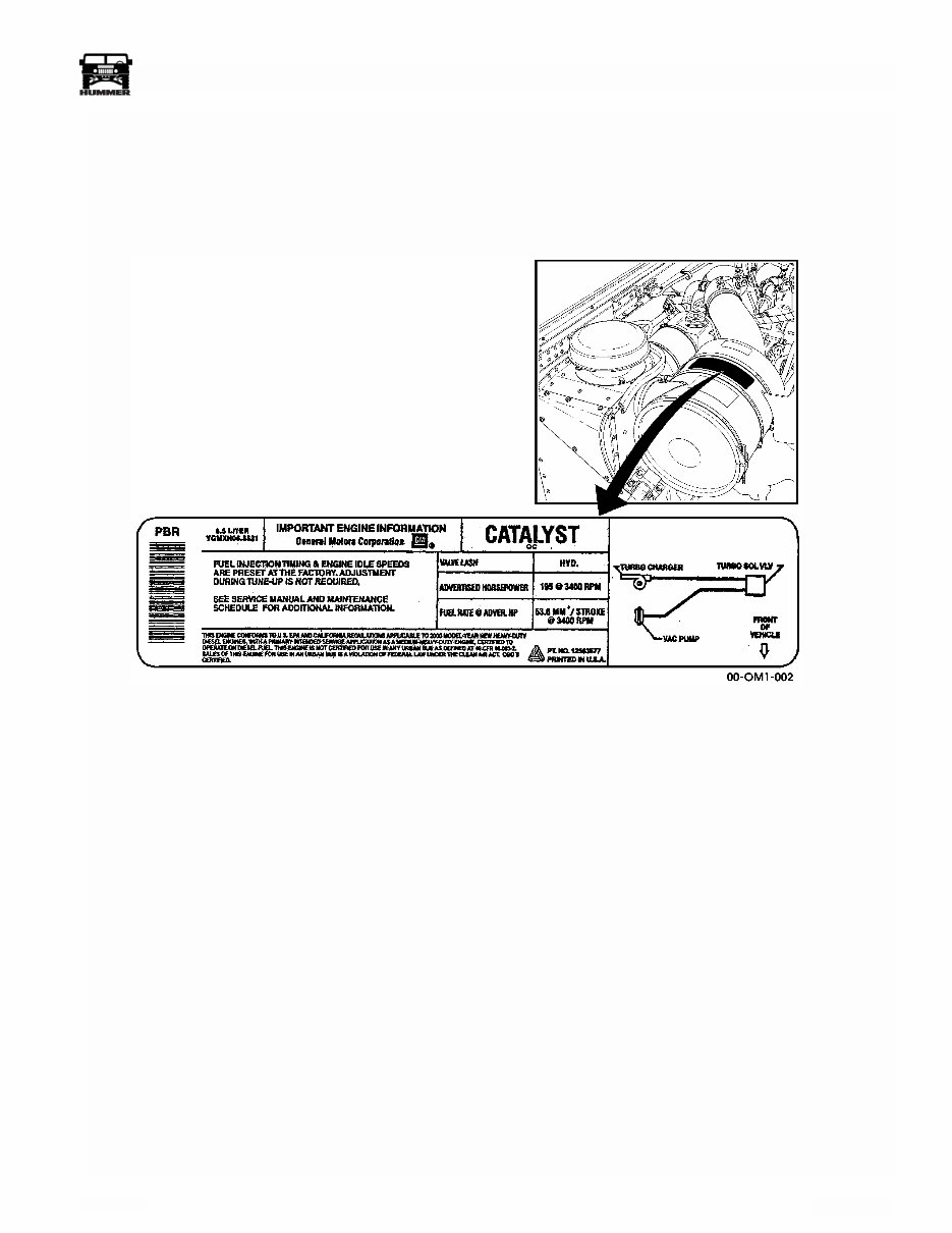
EMISSION CONTROL INFORMATION LABEL
The vehicle emission control label contains engine information
such as curb idle rpm, engine displacement, catalytic converter
type, fuel rate, and vacuum hose routing.
This label is affixed to the air cleaner housing (Figure 1-1).
Figure 1-1: Emission Control Information Label Information
1-4 General Information, Lubrication and Maintenance
_________________
®
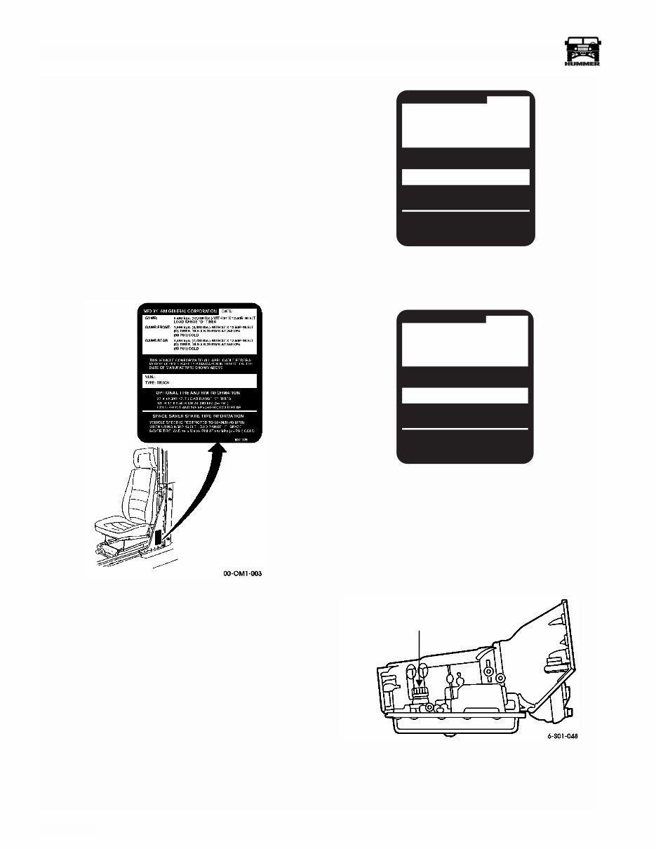
SAFETY CERTIFICATION LABEL
The safety certification label is located on the driver side B-
pillar (door latch post) (Figures 1-2, 1-3, and 1-4). The label is
required by the National Highway Traffic Safety Administra-
tion and includes a tamper-proof feature. If the label is tam-
pered with, a void pattern will appear across the label.
The label contains the name of the manufacturer, the month
and year the vehicle was manufactured, the certification state-
ment, the vehicle identification number (VIN), and the vehicle
model type. It also contains the Gross Vehicle Weight Rating
(GVWR), Gross Axle Weight Ratings (GAWR), and wheel
and tire information. For more information on the GVWR and
GAWR, refer to “VEHICLE LOADING INFORMATION” in
the Hummer Owner’s Manual.
Figure 1-2: Safety Certification Label
for Fleet Vehicles (12,100 lb. GVW vehicles)
Figure 1-3: Safety Certification Label for
10,300 lb GVWR Vehicles
Figure 1-4: Safety Certification Label for
10,800 lb GVWR Vehicles
TRANSMISSION IDENTIFICATION
The 4L80-E automatic transmission serial number is located on
a plate at the right side of the transmission (Figure 1-5).
Figure 1-5: Transmission I.D. Plate Location
MFD BY: AM GENERAL CORPORATION DATE:
GVWR:
GAWR FRONT:
GAWR REAR:
4,672 kgs. (10,300 lbs.) WITH 37 X 12.50R-16.5LT
LOAD RANGE "D" TIRES
1,860 kgs. (4,100 lbs.) WITH 37 X 12.50R-16.5LT
(D) TIRES, 16.5 X 8.25 RIMS AT 240 kPa
(35 PS I) COLD
3,084 kgs. (6,800 lbs.) WITH 37 X 12.50R-16.5LT
(D) TIRES, 16.5 X 8.25 RIMS AT 276 kPa
(40 PS I) COLD
V.I.N.:
TYPE: TRUCK
THIS VEHICLE CONFORMS TO ALL APPLICABLE FEDERAL
MOTOR VEHICLE SAFETY STANDARDS IN EFFECT ON THE
DATE OF MANUFACTURE SHOWN ABOVE
37 X 12.50R-17LT LOAD RANGE "E" TIRES,
WITH 17 X 8.50 RIMS AT 240 kPa (35 PS I)
COLD FRONT AND 276 kPa (40PS I) COLD REAR.
OPTIONAL TIRE AND RIM INFORMATION
VEHICLE SPEED IS RESTRICTED TO 60KM/H (40 MPH)
WHEN USING 9.50R-16.5LT LOAD RANGE "E" SPACE
SAVER TIRE, AND 16.5 X 8.25 RIM AT 517 kPa (75 PS I) COLD.
SPACE SAVER SPARE TIRE INFORMATION
6011176
00-OM1-006
MFD BY: AM GENERAL CORPORATION DATE:
GVWR:
GAWR FRONT:
GAWR REAR:
4,900 kgs. (10,800 lbs.) WITH 37 X 12.50R-16.5LT
LOAD RANGE "D" TIRES
1,860 kgs. (4,100 lbs.) WITH 37 X 12.50R-16.5LT
(D) TIRES, 16.5 X 8.25 RIMS AT 240 kPa
(35 PS I) COLD
3,084 kgs. (6,800 lbs.) WITH 37 X 12.50R-16.5LT
(D) TIRES, 16.5 X 8.25 RIMS AT 276 kPa
(40 PS I) COLD
V.I.N.:
TYPE: TRUCK
THIS VEHICLE CONFORMS TO ALL APPLICABLE FEDERAL
MOTOR VEHICLE SAFETY STANDARDS IN EFFECT ON THE
DATE OF MANUFACTURE SHOWN ABOVE
37 X 12.50R-17LT LOAD RANGE "E" TIRES,
WITH 17 X 8.50 RIMS AT 240 kPa (35 PS I)
COLD FRONT AND 276 kPa (40PS I) COLD REAR.
OPTIONAL TIRE AND RIM INFORMATION
VEHICLE SPEED IS RESTRICTED TO 60KM/H (40 MPH)
WHEN USING 9.50R-16.5LT LOAD RANGE "E" SPACE
SAVER TIRE, AND 16.5 X 8.25 RIM AT 517 kPa (75 PSI) COLD.
SPACE SAVER SPARE TIRE INFORMATION
6011177
00-OM1-005
TRANSMISSION
I.D. PLATE
________________
General Information, Lubrication and Maintenance 1-5
®
5745279
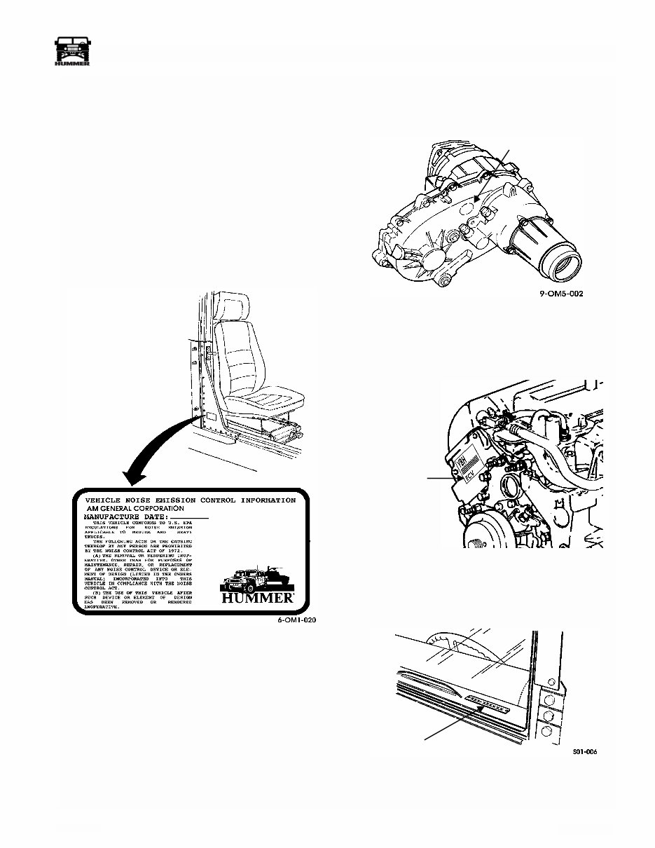
EPA NOISE EMISSION CONTROL INFORMA-
TION LABEL
The EPA noise emission control information label is located on
the passenger side B-pillar (door latch post). The label is re-
quired by the EPA and includes a tamper-proof feature. If the
label is tampered with, a void pattern will appear across the la-
bel. Notify the dealer or the manufacturer if the label is missing
or displays a void pattern (Figure 1-6).
The label contains the name of the manufacturer, the month
and year the vehicle was manufactured, a statement regarding
vehicle conformance to applicable U.S. EPA regulations, and a
description of acts prohibited by the Noise Control Act of
1972.
Figure 1-6: EPA Noise Emission Control
Information Label Location
TRANSFER CASE IDENTIFICATION
The transfer case serial and assembly numbers are located on a
tag attached to the rear case (Figure 1-7).
Figure 1-7: Transfer Case I.D. Plate Location
ENGINE IDENTIFICATION
The engine serial number label is located at the rear of the left
cylinder head (Figure 1-8).
Figure 1-8: Engine I.D. Label Location
VEHICLE IDENTIFICATION NUMBER (VIN)
The VIN plate is located at the upper left front corner of the
dashpad (Figure 1-9).
Figure 1-9: VIN Plate Location
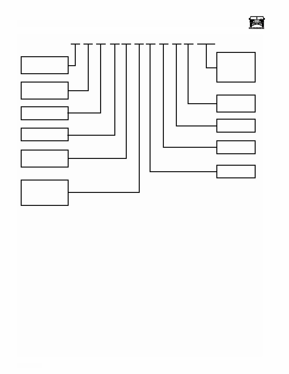
The first twelve digits of the seventeen digit VIN are explained
in the chart on the following page.
TRANSFER CASE SERIAL NUMBER
(ON ID PLATE)
ENGINE SERIAL
NUMBER LABEL
VIN PLATE
1-6 General Information, Lubrication and Maintenance
_________________
®
1 3 7 Z A 89 3 4 1 E 000001
Digit 1
Manufacturing
Country
Digit 2
Company/Make
Digit 3
Vehicle Type
Digit 4
Engine Type
Digit 5
Transmission/Drive
Digit 6 and 7
Truck Line Series
Model, Body Type
Digit 12
Sequential,
Assigned
Serial Number
Digit 11
Plant Code
Digit 10
Model Year
Digit 9
Check Digit
Digit 8
GVWR
through 17
Vehicle Identification Number Decoding Chart
Digit Code Code Definition
1 1 United States
2 3 AM General Corporation
3 7 Commercial Vehicles
4 Z 6.5L (395 in.
3
),Turbocharged Diesel, GM, 8 cyl., 195 hp
F 6.5L (395 in.
3
),Turbocharged Diesel, GEP, 8 cyl.,195 hp
5 A 4-Speed, Automatic/LHD
6 & 7 83 1-1/4 ton 4-door Truck, utility
84 1-1/4 ton Station wagon Truck, utility
89 1-1/4 ton 2-door enlarged cab Truck, utility
90 1-1/4 ton Open body w/full hard doors Truck, utility
91 1-1/4 ton Slant Back Truck, utility
8 3 Class 3, 10,001 lb - 14,000 lb (4,541 kg - 6,356 kg)
9 — Check Digit
10 1 2001
11 E Mishawaka, Indiana
12-17 — Sequential Serial Number

________________
General Information, Lubrication and Maintenance 1-7
®
5745279
COMPONENT DATA
Engine:
Manufacturer .................................................................................................................................................... GM Powertrain or GEP
Model ........................................................................................................................................................................... 6.5 L (395 in.
3
)
Type .........................................................................................................................Four Cycle, Turbocharged Diesel, Liquid-Cooled
Power Output: ..................................................................................................... 195 HP @ 3400 rpm/430 ft lb. Torque @ 1800 rpm
Engine Dimensions:
Length.............................................................................................................................................................................. 35 in. (89 cm)
Width ............................................................................................................................................................................... 28 in. (71 cm)
Height .............................................................................................................................................................................. 28 in. (71 cm)
Net Weight, Dry ............................................................................................................................................................ 701 lb (318 kg)
Governed Speed:
Full Load ............................................................................................................................................................................ 3,400 RPM
No Load .............................................................................................................................................................................. 3,650 RPM
Idle Speed ............................................................................................................................................................................... 700 RPM
Operating Speed ........................................................................................................................................................ 1,500-2,600 RPM
Cylinders:
Number ................................................................................................................................................................................................. 8
Arrangement ................................................................................................................................................................................. 90° V
Firing Order .............................................................................................................................................. 1-8-7-2-6-5-4-3 (Clockwise)
Bore ...................................................................................................................................................................... 4.06 in. (103.12 mm)
Stroke ......................................................................................................................................................................... 3.82 in. (9.7 cm)
Displacement ................................................................................................................................................................. 6.5 L (395 in.
3
)
Compression Ratio: ......................................................................................................................................................................20.2:1
Lubricating System:
Type ................................................................................................................................................................................. Pressure Feed
Operating Pressure:
(Minimum) ................................................................................................................................. 30 psi (206.8 kPa) @ 2000 RPM
(Idle Minimum) ..................................................................................................................................................... 6 psi (41.3 kPa)
System Capacity (Filter Included)...................................................................................................................................... 8 qt (7.6 L)
Operating Temperature (Normal)................................................................................................................. 180°-275° F (82°-135° C)
Oil Pump ............................................................................................................................................................................High Output
Filter ................................................................................................................................................................ Paper Element, Spin On
Fuel/Air System:
Fuel Supply Pump Type ....................................................................................................................................................... Electronic
Fuel Filter Type ...................................................................................................................... Two Stage Fuel Filter /Water Separator
Glow Plug Type ........................................................................................................................................................... (11G) Fast Start
Starter:
Manufacturer ...........................................................................................................................................................................Prestolite
Model ........................................................................................................................................................................................... MMO
Capacity (Peak) ........................................................................................................................................................................... 6.0 hp
Voltage ........................................................................................................................................................................................... 12 V
Cooling System:
Type ........................................................................................................................................................... Liquid w/Fan and Radiator
Operating Temperature. ............................................................................................................................... 190°-235° F (88°-113° C)
Filler Cap Pressure ...................................................................................................................................................... 15 psi (103 kPa)
Radiator Type .................................................................................................................................................. 4 Row Core Downflow
Fan Type ..............................................................................................................................................8 Blade,suction w/viscous drive
Fan Diameter ............................................................................................................................................................ 19.5 in. (49.5 cm)

1-8 General Information, Lubrication and Maintenance
_________________
®
Thermostat:
Starts to Open .......................................................................................................................................................... 190° F (88° C)
Fully Open ............................................................................................................................................................. 212° F (100° C)
Generator:
Manufacturer ................................................................................................................................................................................ Delco
Output ................................................................................................................................................. 124 AMP @ 1842 Engine RPM
Rated Voltage .................................................................................................................................................................. 13.35 -15.9 V
Batteries:
Manufacturer ..............................................................................................................................................................Johnson Controls
Type .......................................................................................................................................................................... Low Maintenance
Number ............................................................................................................................................................................................... 2
Voltage ...........................................................................................................................................................................................12 V
Amperage
@ 0° F ...............................................................................................................................800 Cold Cranking amps Each Battery
32° F ...............................................................................................................................1000 Cold Cranking amps Each Battery
80° F ............................................................................................................................................110 Reserve Capacity (Minutes)
Transmission:
Manufacturer ................................................................................................................................................................ GM Powertrain
Model ......................................................................................................................................................................................... 4L80-E
Type ...................................................................................................................................................................... 4-Speed, Automatic
Converter Torque Ratio ................................................................................................................................................................ 2.2:1
Gear Ratios:
First...................................................................................................................................................................................... 2.48:1
Second ................................................................................................................................................................................. 1.48:1
Third .................................................................................................................................................................................... 1.00:1
Fourth .................................................................................................................................................................................. 0.75:1
Reverse ....................................................................................................................................................................................... 2.08:1
Oil Type .............................................................................................................................................................................. Dexron
®
III
Oil Pressure .............................................................................................................................................. 35-324 psi (241-2,234 kPa)
Transfer Case:
Manufacturer ........................................................................................................................................................... New Venture Gear
Model ................................................................................................................................................................................................ 242
Type ......................................................................................................................................................... Full Time Four-Wheel Drive
Gear Ratios
High and High Lock ..........................................................................................................................................................................1:1
Low Range................................................................................................................................................................................... 2.72:1
Oil Type .............................................................................................................................................................................. Dexron
®
III
Geared Hub:
Manufacturer ......................................................................................................... AM General Corporation design, made by Tremec
Type ...................................................................................................................................................................................... Spur Gears
Gear Ratio.....................................................................................................................................................................................1.92:1
Oil Type ................................................................................................................................................................................ SAE 80-90
Axle/Differential:
Manufacturer ............................................................................................................. AM General Corporation design, made by Dana
Type:
Axle ...................................................................................................... Fixed Mounted Differential W/ Independent Half Shafts
Differential .............................................................................................................Hypoid Torque Biasing (Paired Worm Gears)
Gear Ratio:
10,300 and 10,800: ................................................................................................................................................................2.56:1
12,100:...................................................................................................................................................................................3.08:1

________________
General Information, Lubrication and Maintenance 1-9
®
5745279
Service Brake Caliper (Front):
Manufacturer ................................................................................................................................................................... Kelsey-Hayes
Piston Diameter ............................................................................................................................................................ 2.6 in. (6.6 cm)
Service/Parking Brake Caliper (Rear):
Manufacturer ................................................................................................................................................................... Kelsey-Hayes
Piston Diameter ............................................................................................................................................................ 2.6 in. (6.6 cm)
Service/Parking Brake Rotor:
Manufacturer ................................................................................................................................................................... Kelsey-Hayes
Diameter ................................................................................................................................................................ 10.5 in. (266.7 mm)
Thickness .................................................................................................................................................................... 0.87 in. (22 mm)
Minimum Thickness ................................................................................................................................................. 0.81 in. (20.7 mm)
Steering System:
Steering Gear:
Manufacturer ..................................................................................................................................................................... Saginaw
Type ......................................................................................................................................... Recirculating Ball, Worm and Nut
Ratio ................................................................................................................................................................................... 13/16:1
Power Steering Pump:
Manufacturer ..................................................................................................................................................................... Saginaw
Output Pressure (Max) .................................................................................................... 1,465 - 1,515 psi (10,101 - 10,446 kPa)
Flow Rate (Max) ........................................................................................................................................... 2.6 gpm (9.8 Lpm)
Capacity (@ 1500 RPM) .............................................................................................................................. 2.6 gpm (9.8 Lpm)
Reservoir ............................................................................................................................................................................ Remote
Frame:
Manufacturer ............................................................................................................. AM General Corporation design, made by Dana
Type ........................................................................................................................................................................................ Steel Box
No. of Crossmembers ........................................................................................................................................................................... 5
Air Conditioner:
Manufacturer (Compressor) ............................................................................................................................................. GM-Harrison
Model ............................................................................................................................................................................................ HD-6
Field (Coil) ..................................................................................................................................................................................... 12 V
Oil Capacity.................................................................................................................................................................. 8 fl oz (237 ml)
Refrigerant .................................................................................................................................................................................. R-134a
Capacity (system + 2 oz. of oil) .................................................................................................................................. 3.2 lb. (1.45 kg)
Winch:
Manufacturer ................................................................................................................................................................................. Warn
Model ................................................................................................................................................... 12,000 lb., 12VDC HUMMER
Type .......................................................................................................................................... Electric Drive, Thermal Cutoff Switch
Capacity................................................................................................................................................................. 12,000 lb (5,448 kg)
Wheels and Tires:
Manufacturer ..........................................................................................................................Goodyear Tire Size 37 in. X 12.5R-16.5
Wheel Type:
Standard ......................................................................................................................................................................... One-Piece
Size ........................................................................................................................................................................... 16.5 x 8.25 in.
You're Reading a Preview
What's Included?
Fast Download Speeds
Offline Viewing
Access Contents & Bookmarks
Full Search Facility
Print one or all pages of your manual
$27.99
Viewed 70 Times Today


Secure transaction
What's Included?
Fast Download Speeds
Offline Viewing
Access Contents & Bookmarks
Full Search Facility
Print one or all pages of your manual
$27.99
The Hummer H1 1995-2007 workshop manual is a comprehensive guide for professional mechanics and DIY enthusiasts. It includes detailed information on the 6.6 td v8, 6.5 td v8 turbo diesel, and n/a engines, along with electrical wiring diagrams. The manual is available in PDF format, ensuring ease of access and readability.
- General information
- Engine
- Clutch
- Gearbox
- Propeller shafts
- Rear axles
- Front axle
- Front and rear suspensions
- Wheels and tyres
- Steering system
- Brakes
- Bodywork and chassis frame
- Maintenance
- Electric/Electronic System
- And more
This manual covers everything essential for maintaining and repairing this type of 4x4 vehicle.


