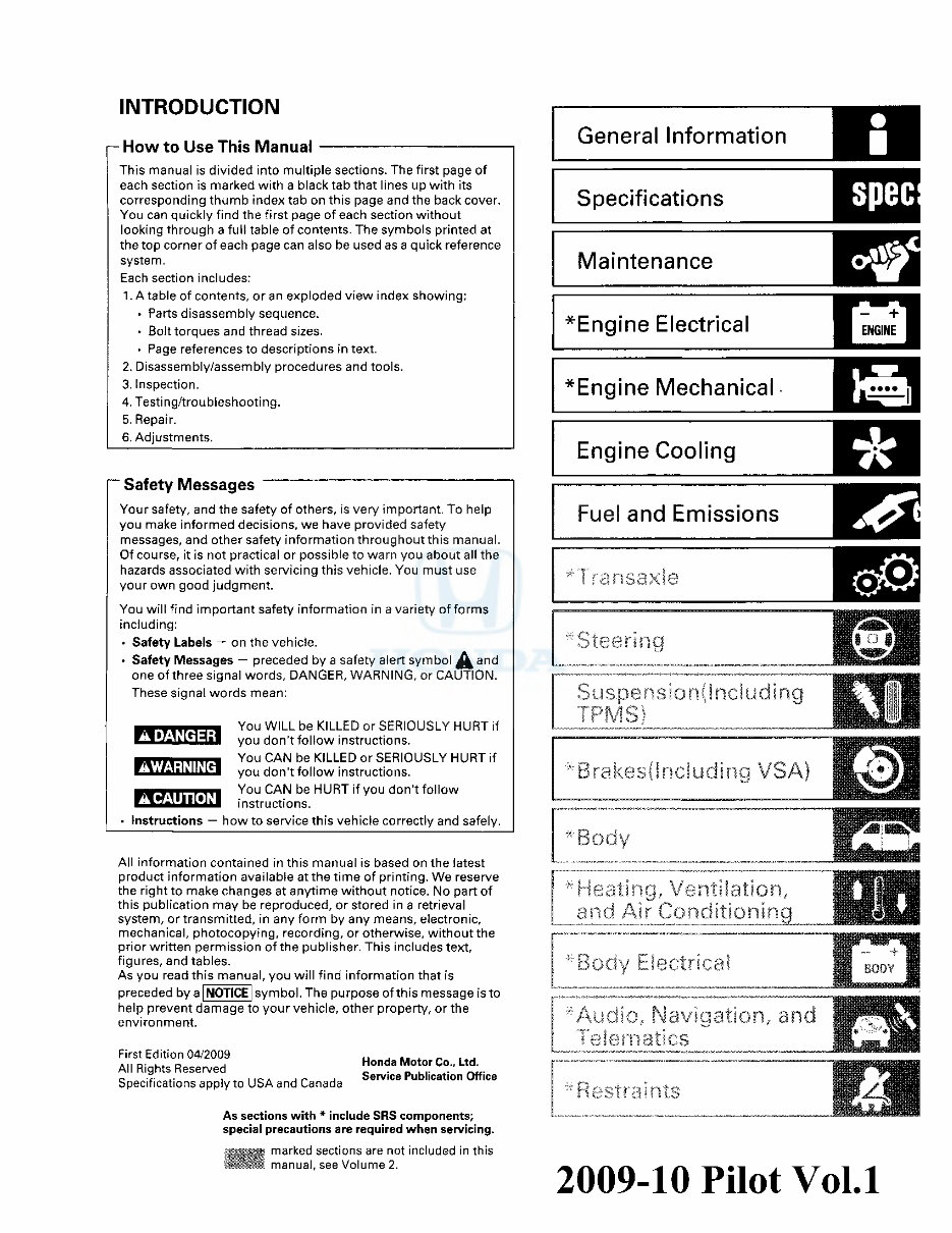
INTRODUCTION i— How to Use This Manual This manual is divided into multiple sections. The first page of each section is marked with a black tab that lines up with its corresponding thumb index tab on this page and the back cover. You can quickly find the first page of each section without looking through a full table of contents. The symbols printed at the top corner of each page can also be used as a quick reference system. Each section includes: 1. A table of contents, or an exploded view index showing: • Parts disassembly sequence. • Bolt torques and thread sizes. • Page references to descriptions in text. 2. Disassembly/assembly procedures and tools. 3. Inspection. 4. Testing/troubleshooting. 5. Repair. 6. Adjustments. Safety Messages Your safety, and the safety of others, is very important. To help you make informed decisions, we have provided safety messages, and other safety information throughout this manual. Of course, it is not practical or possible to warn you about all the hazards associated with servicing this vehicle. You must use your own good judgment. You will find important safety information in a variety of forms including: • Safety Labels — on the vehicle. • Safety Messages — preceded by a safety alert symbol fa and one of three signal words, DANGER, WARNING, or CAUTION. These signal words mean: ADANGER ^WARNING A CAUTION Instructions . You WILL be KILLED or SERIOUSLY HURT if I you don't follow instructions. • You CAN be KILLED or SERIOUSLY HURT if I you don't follow instructions. i You CAN be HURT if you don't follow I instructions. how to service this vehicle correctly and safely. All information contained in this manual is based on the latest product information available at the time of printing. We reserve the right to make changes at anytime without notice. No part of this publication may be reproduced, or stored in a retrieval system, or transmitted, in any form by any means, electronic, mechanical, photocopying, recording, or otherwise, without the prior written permission of the publisher. This includes text, figures, and tables. As you read this manual, you will find information that is preceded by a | NOTICE | symbol. The purpose of this message is to help prevent damage to your vehicle, other property, or the environment. First Edition 04/2009 All Rights Reserved Specifications apply to USA and Canada Honda Motor Co., Ltd. Service Publication Office As sections with * include SRS components; special precautions are required when servicing. >; marked sections are not included in this llllllll manual, see Volume 2. General Information Specifications Maintenance ^Engine Electrical Engine Mechanical Engine Cooling Fuel and Emissions " Transaxie *Steering Suspension! Including TPMS) ' BrakesOnciuding VSA Body *Heoiiny, Ventilation, and Air Conditioning *Bociy blectrical "Audio., Navigation,, and T?-!err id tics testraints 2009-10 Pilot Vol.1 chodina@live.co.uk chodina@live.co.uk
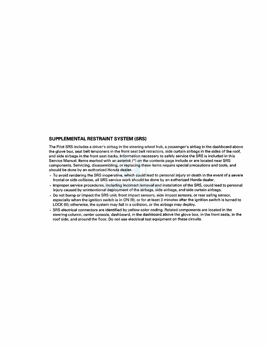
SUPPLEMENTAL RESTRAINT SYSTEM (SRS) The Pilot SRS includes a driver's airbag in the steering wheel hub, a passenger's airbag in the dashboard above the glove box, seat belt tensioners in the front seat belt retractors, side curtain airbags in the sides of the roof, and side airbags in the front seat-backs. Information necessary to safely service the SRS is included in this Service Manual. Items marked with an asterisk (*) on the contents page include or are located near SRS components. Servicing, disassembling, or replacing these items require special precautions and tools, and should be done by an authorized Honda dealer. • To avoid rendering the SRS inoperative, which could lead to personal injury or death in the event of a severe frontal or side collision, all SRS service work should be done by an authorized Honda dealer. • Improper service procedures, including incorrect removal and installation of the SRS, could lead to personal injury caused by unintentional deployment of the airbags, side airbags, and side curtain airbags. • Do not bump or impact the SRS unit, front impact sensors, side impact sensors, or rear safing sensor, especially when the ignition switch is in ON (II), or for at least 3 minutes after the ignition switch is turned to LOCK (0); otherwise, the system may fail in a collision, or the airbags may deploy. • SRS electrical connectors are identified by yellow color coding. Related components are located in the steering column, center console, dashboard, in the dashboard above the glove box, in the front seats, in the roof side, and around the floor. Do not use electrical test equipment on these circuits. chodina@live.co.uk chodina@live.co.uk
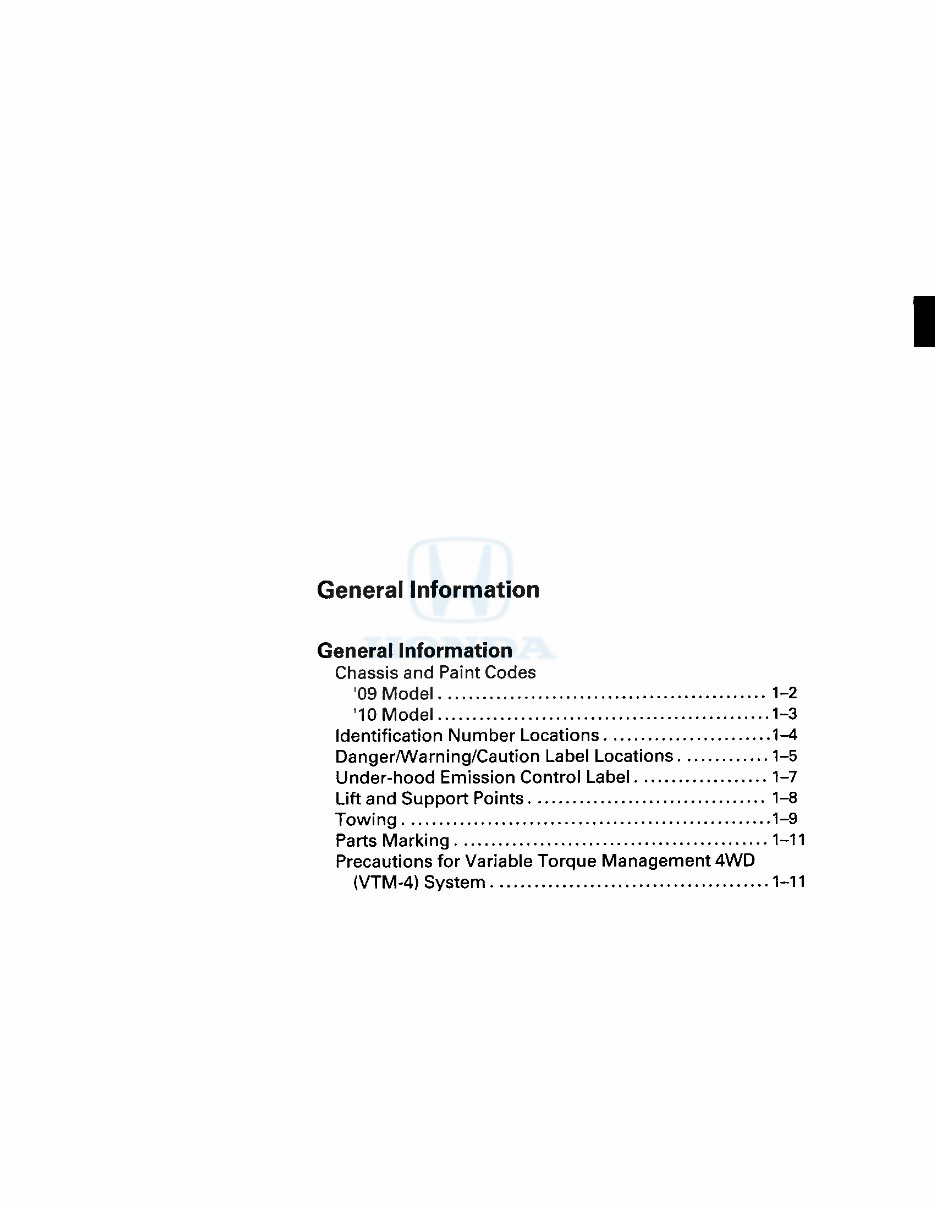
General Information General Information Chassis and Paint Codes '09 Model 1-2 '10 Model 1-3 Identification Number Locations 1-4 Danger/Warning/Caution Label Locations 1-5 Under-hood Emission Control Label 1-7 Lift and Support Points 1-8 Towing 1-9 Parts Marking 1-11 Precautions for Variable Torque Management 4WD (VTM-4) System 1-11 chodina@live.co.uk chodina@live.co.uk
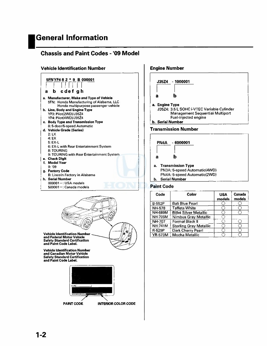
I General Information Chassis and Paint Codes - '09 Model Vehicle Identification Number 5FNYF48 2 * 9 B 000001 rrrrrrri a b c d e f g h a. Manufacturer, Make and Type of Vehicle 5FN: Honda Manufacturing of Alabama, LLC Honda multipurpose passenger vehicle b. Line, Body and Engine Type YF3: Pilot(2WD)/J35Z4 YF4: Pilot(4WD)/J35Z4 c. Body Type and Transmission Type 8: 5-door/5-speed Automatic d. Vehicle Grade (Series) 2:LX 4: EX 5: EX-L 6: EX-L with Rear Entertainment System 8: TOURING 9: TOURING with Rear Entertainment System e. Check Digit f. Model Year 9: '09 g. Factory Code B: Lincoln Factory in Alabama h. Serial Number 000001-: USA models 500001 -: Canada models Vehicle Identification Number and Federal Motor Vehicle Safety Standard Certification and Paint Code Label. Vehicle Identification Number and Canadian Motor Vehicle Safety Standard Certification and Paint Code Label. Engine Number J35Z4 - 1000001 a a. Engine Type J35Z4: 3.5 L SOHC i-VTEC Variable Cylinder Management Sequential Multiport Fuel-injected engine b. Serial Number Transmission Number PN4A - 6000001 a a. Transmission Type PN3A: 5-speed Automatic(4WD) PN4A: 5-speed Automatic(2WD) b. Serial Number Paint Code Code Color USA Canada models models B-552P Bali Blue Pearl o O NH-578 Taffeta White o O NH-689M Billet Silver Metallic o o NH-705M Nimbus Gray Metallic o NH-707 Formal Black II o o NH-741M Sterling Gray Metallic o o R-529P Dark Cherry Pearl o o YR-573M Mocha Metallic o o PAINT CODE INTERIOR COLOR CODE 1-2 chodina@live.co.uk chodina@live.co.uk
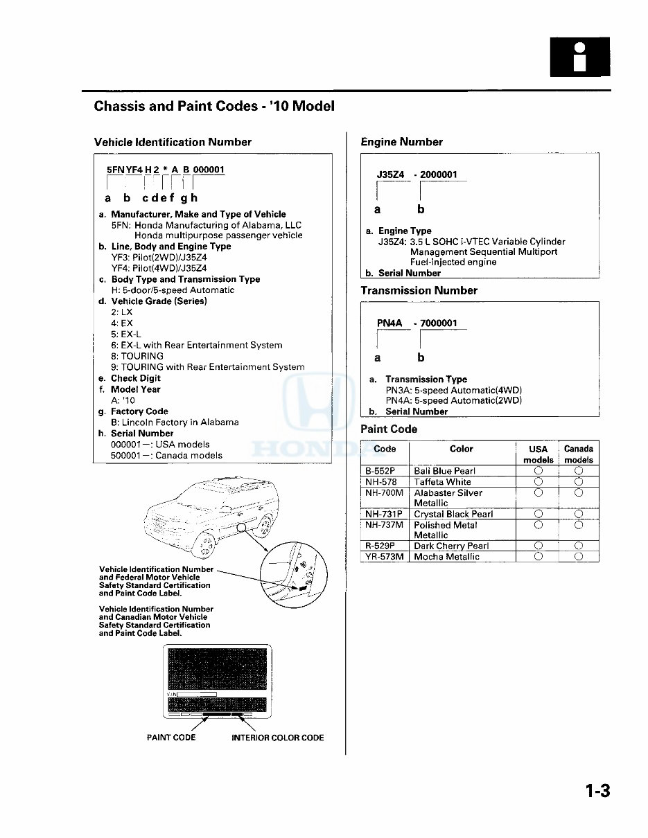
Chassis and Paint Codes - '10 Model Vehicle Identification Number Engine Number 5FN YF4 H 2 * A B 000001 rrrrrrri a b c de f g h a. Manufacturer, Make and Type of Vehicle 5FN: Honda Manufacturing of Alabama, LLC Honda multipurpose passenger vehicle b. Line, Body and Engine Type YF3: Pilot(2WD)/J35Z4 YF4: Pilot(4WD)/J35Z4 c. Body Type and Transmission Type H: 5-door/5-speed Automatic d. Vehicle Grade (Series) 2: LX 4: EX 5: EX-L 6: EX-L with Rear Entertainment System 8: TOURING 9: TOURING with Rear Entertainment System e. Check Digit f. Model Year A: '10 g. Factory Code B: Lincoln Factory in Alabama h. Serial Number 000001-: USA models 500001 —: Canada models and Canadian Motor Vehicle Safety Standard Certification and Paint Code Label. PAINT CODE INTERIOR COLOR CODE J35Z4 -2000001 a b a. Engine Type J35Z4: 3.5 L SOHC i-VTEC Variable Cylinder Management Sequential Multiport Fuel-injected engine b. Serial Number Transmission Number PN4A - 7000001 a b a. Transmission Type PN3A: 5-speed Automatic(4WD) PN4A: 5-speed Automatic(2WD) b. Serial Number Paint Code Code Color USA Canada models models B-552P Bali Blue Pearl O O NH-578 Taffeta White o o NH-700M Alabaster Silver o o Metallic NH-731P Crystal Black Pearl o o NH-737M Polished Metal o o Metallic R-529P Dark Cherry Pearl o o YR-573M Mocha Metallic o o 1-3 chodina@live.co.uk chodina@live.co.uk
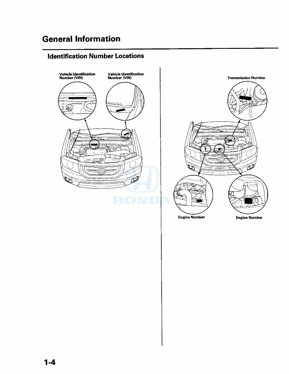
General Information Identification Number Locations Vehicle Identification Number (VIN) Vehicle Identification Number (VIN) Transmission Number Engine Number Engine Number 1-4 chodina@live.co.uk chodina@live.co.uk
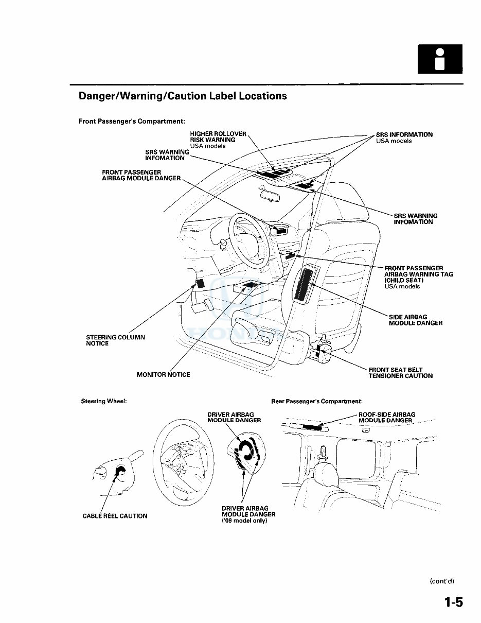
Danger/Warning/Caution Label Locations Front Passenger's Compartment: (cont'd) 1-5 chodina@live.co.uk chodina@live.co.uk
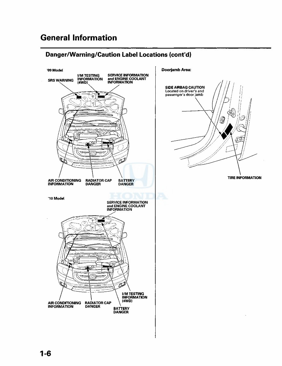
General Information Danger/Warning/Caution Label Locations (cont'd) 09 Model l/M TESTING SERVICE INFORMATION SR<3 WARNING INFORMATION and ENGINE COOLANT WARNlNij ( 4 W D ) INFORMATION AIR CONDITIONING RADIATOR CAP BATTERY INFORMATION DANGER DANGER 10 Model SERVICE INFORMATION and ENGINE COOLANT INFORMATION Doorjamb Area: SIDE AIRBAG CAUTION Located on driver's and passenger's doorjamb TIRE INFORMATION AIR CONDITIONING RADIATOR CAP INFORMATION DANGER l/M TESTING INFORMATION (4WD) BATTERY DANGER 1-6 chodina@live.co.uk chodina@live.co.uk
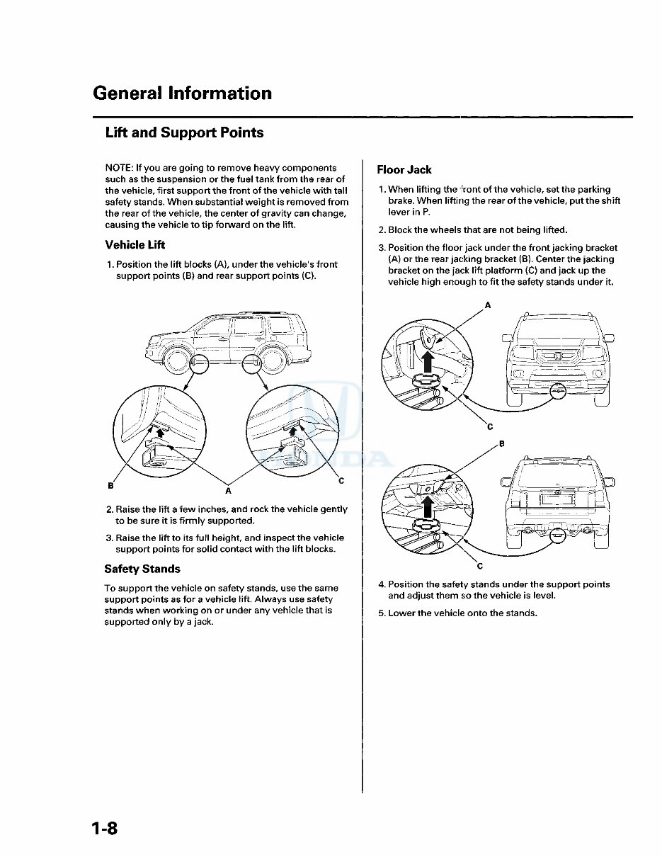
General Information Lift and Support Points NOTE: If you are going to remove heavy components such as the suspension or the fuel tank from the rear of the vehicle, first support the front of the vehicle with tall safety stands. When substantial weight is removed from the rear of the vehicle, the center of gravity can change, causing the vehicle to tip forward on the lift. Vehicle Lift 1. Position the lift blocks (A), under the vehicle's front support points (B) and rear support points (C). 2. Raise the lift a few inches, and rock the vehicle gently to be sure it is firmly supported. 3. Raise the lift to its full height, and inspect the vehicle support points for solid contact with the lift blocks. Safety Stands To support the vehicle on safety stands, use the same support points as for a vehicle lift. Always use safety stands when working on or under any vehicle that is supported only by a jack. Floor Jack 1. When lifting the front of the vehicle, set the parking brake. When lifting the rear of the vehicle, put the shift lever in P. 2. Block the wheels that are not being lifted. 3. Position the floor jack under the front jacking bracket (A) or the rear jacking bracket (B). Center the jacking bracket on the jack lift platform (C) and jack up the vehicle high enough to fit the safety stands under it. A 4. Position the safety stands under the support points and adjust them so the vehicle is level. 5. Lower the vehicle onto the stands. 1-8 chodina@live.co.uk chodina@live.co.uk
The 2012 Honda Pilot OEM Service & Repair Manual delivers factory-correct procedures, diagnostic steps, and technical specifications for the third-generation Pilot equipped with the 3.5L J35Z4 V6 engine. Covering both 2WD and 4WD variants, this manual is the go-to reference for technicians and serious DIYers working on the PN3A and PN4A 5-speed automatic transmissions.
From complete engine teardown to transmission overhauls, electrical diagnostics, and interior disassembly, this manual covers every system with OEM-grade accuracy. Whether you’re performing a routine service or tackling a complex drivetrain issue, this guide ensures repairs are done right, with full access to torque specs, wiring diagrams, and component test procedures.
Content Overview:
General service guidelines and repair safety information
Full vehicle specifications including torque values and fluid types
Factory-recommended maintenance schedules and procedures
Engine electrical diagnostics, sensors, and wiring repair
Engine mechanical service including timing components and internals
Cooling system repair including radiator, thermostat, and water pump
Fuel delivery and emissions system troubleshooting
Transaxle inspection, adjustment, and overhaul procedures
Steering system diagnostics and repair including EPS components
Suspension system service including TPMS and ride height inspection
Braking system repair including ABS and VSA (Vehicle Stability Assist)
Body panel, trim, and interior disassembly and service procedures
HVAC repair including blower motor, heater core, and A/C service
Body electrical diagnostics and troubleshooting
Audio, navigation, and telematics system repair and wiring
Airbag system servicing and restraint module diagnostics
Whether you're maintaining a high-mileage family hauler or performing more in-depth repairs, this manual delivers the same service information used at the dealership. It’s a critical resource for ensuring long-term reliability and factory-standard results.
Printable: Yes Language: English Compatibility: Pretty much any electronic device Requirements: Adobe Reader (free)


 Lifetime Access




