How to Use this Manual The next few pages describe how this manual is organized. They also explain what kind of information the manual contains, what the information means, and how to use it to troubleshoot electrical problems. Circuit schematics break the entire electrical system into individual systems, such as the Back-up Lights on the next page. Only electrical components that work together are shown together, so you will not be distracted by unrelated wires. Explanations of the abbreviations and symbols used in the schematics begin on page 7. You will need to know what they mean before you can use a schematic effectively. 1
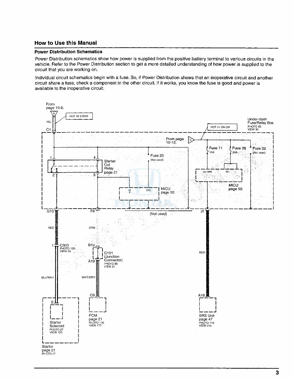
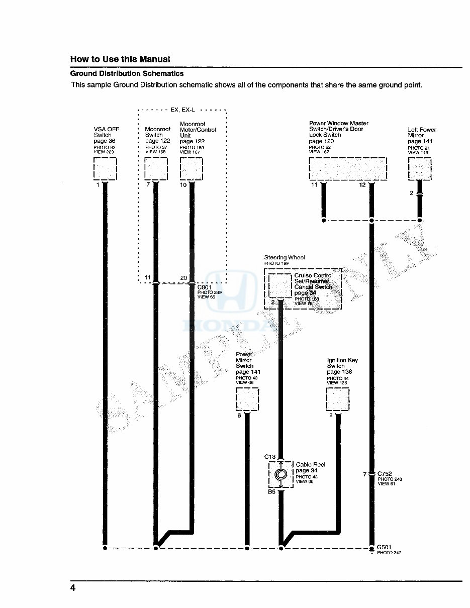
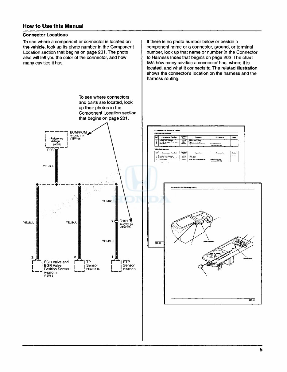
How to Use this Manual Circuit Schematics Each schematic represents one circuit. A circuit's wires and components are arranged to show current flow, from power at the top of the page, to ground at the bottom. Shared Circuits Other circuits may share power or ground terminals or wiring with the circuit shown. A wire that connects one circuit to another, for example, is cut short and has an arrowhead at the end of it pointing in the direction of current flow. Next to the arrowhead is the name of the circuit or component which shares that wiring. To quickly check shared wiring, check the operation of a component it serves. If that component works, you know the shared wiring is OK. Connectors All in-line and junction connectors are numbered (C725, C416, etc.). Component connectors are not numbered but are identified either by the name of the component if the component only has one connector, or by a capital letter (A, B, C, etc.) if the component has more than one connector. Below most connector numbers and component names are PHOTO and VIEW numbers. The PHOTO number refers to a photograph in section 201 of this book that shows the connector's location on the vehicle. The VIEW number refers to an illustration in section 202 of this book that shows the connector terminals, wire colors, connector cavity numbers, and other details. The connector cavity numbering sequence begins at the top left corner of the connector as seen from either of the viewpoints shown on page 8. Except for the DLC (data link connector), disregard any numbers molded into the connector housing. Wires Wires are identified by the abbreviated names of their colors; the second color is the color of the stripe. Wires also are identified by their location in a connector. The number "2" next to the male and female wire terminals at C554, for example, means those terminals join in cavity 2 of connector C554. Symbols A complete description of schematic symbols begins on page 7. "HOT" label tells you when the ignition switch supplies power to the fuse. t Arrow with note means other circuits connect here. Capital letter means the driver's under-dash fuse/relay box has more than one connector. Wire color code; defined on page7. Junction connector has one or more bus bars in it; each bar connects two or more wire terminals. \ "YEL A YEL 1 Numbers inside components refer to notes listed below component name. rr GR.* L 'B..K I p Back-up Light Switch transmission in reverse PHOTO 20 GRN/BLK C102 PHOTO 34 VIEW 40 See page 10-9. Arrowhead means wire connects to another circuit; it points in direction of current flow. Cavity number; assigned as shown on page 8. K2 r i L A6 "| Driver's I Under-dash ' Fuse/Relay Box J PHOTO 85 In-line Connector VIEW so number; Index begins on page 203. Number of photo in section 201 showing component location on vehicle. Number of connector terminals view in section 202. (Coupe 1) 2 Right Back-up Light Ground Variations are indicated by model. G601 PHOTO 148 P H O T O 1 5 8 (Coupe) 2
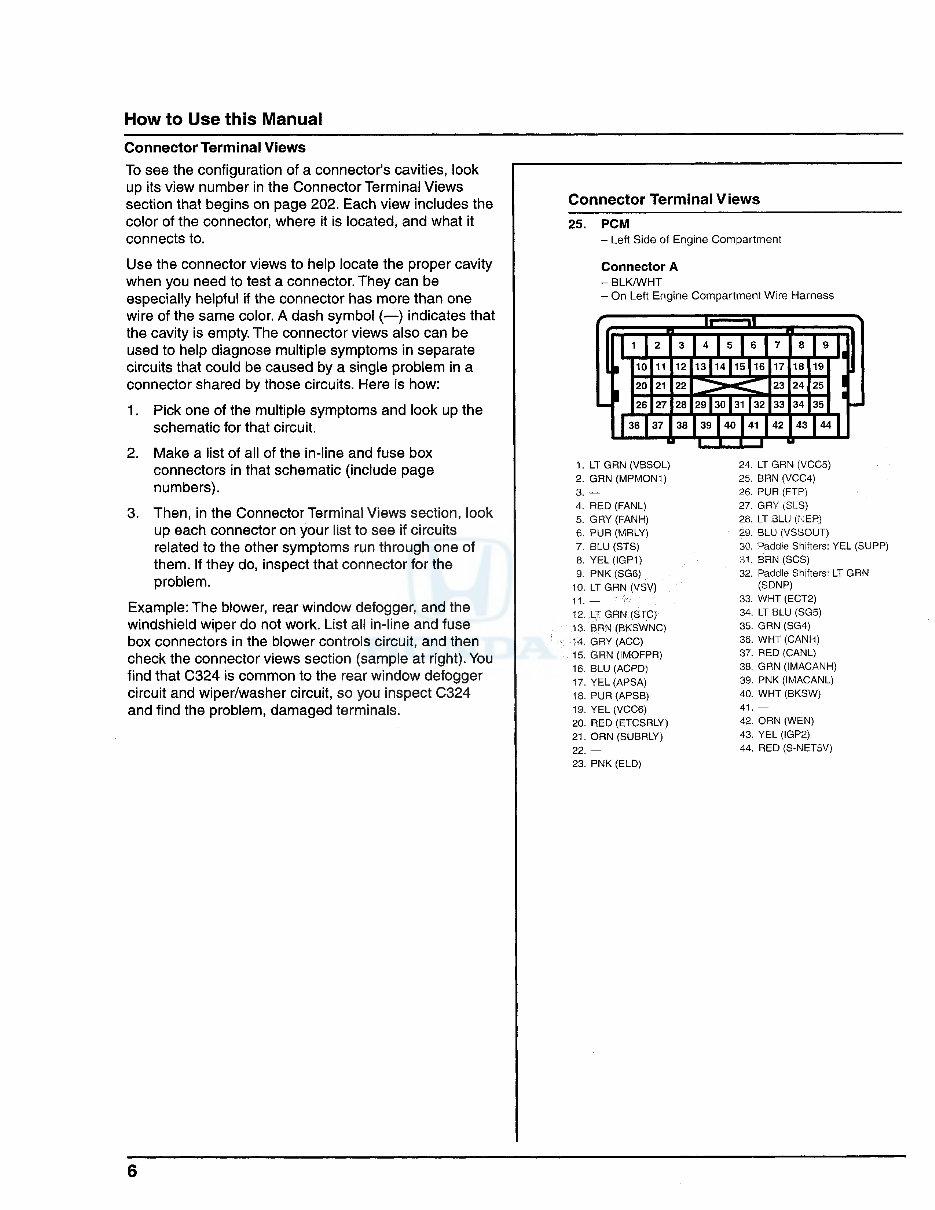
How to Use this Manual Connector Terminal Views To see the configuration of a connector's cavities, look up its view number in the Connector Terminal Views section that begins on page 202. Each view includes the color of the connector, where it is located, and what it connects to. Use the connector views to help locate the proper cavity when you need to test a connector. They can be especially helpful if the connector has more than one wire of the same color. A dash symbol (—) indicates that the cavity is empty. The connector views also can be used to help diagnose multiple symptoms in separate circuits that could be caused by a single problem in a connector shared by those circuits. Here is how: 1. Pick one of the multiple symptoms and look up the schematic for that circuit. 2. Make a list of all of the in-line and fuse box connectors in that schematic (include page numbers). 3. Then, in the Connector Terminal Views section, look up each connector on your list to see if circuits related to the other symptoms run through one of them. If they do, inspect that connector for the problem. Example: The blower, rear window defogger, and the windshield wiper do not work. List all in-line and fuse box connectors in the blower controls circuit, and then check the connector views section (sample at right). You find that C324 is common to the rear window defogger circuit and wiper/washer circuit, so you inspect C324 and find the problem, damaged terminals. Connector Terminal Views 25. PCM - Left Side of Engine Compartment Connector A - BLK/WHT - On Left Engine Compartment Wire Harness • 1 10 11 20 21 26 27 12113 EE 22 28[29pO ^T ]3^ 37 38 I 39 D 1. LT GRN (VBSOL) 24. LT GRN (VCC5) 2. GRN (MPMON1) 25. BRN (VCC4) 3. — 26. PUR (FTP- 4. RED (FANL) 27. GRY ^ S) 5. GRY (FANH) 28. LT 3LU ^JEh) 6. PUR (MRLY) 2i>. BLU fVS'jOUT) 7. BLU (STS) Saddle Shifters: YEL (SUPP) 8. YEL (IGP1) .11. BRN (SCS) 9. PNK (SG6) 32. Paddle Shifters: LT GRN 10. LT GRN (VSV) (SDNP) 11. 33. WHT (ECT2) 12. LT GRN (STC; 34. LT BLU (SG5) 13. BRN (BKSWNC) 35. GRN (SG4) H. GRY (ACC) 36. WHT (CANH) 15. GRN (IMOFPR) 37. RED (CANL) 16. BLU (ACPD) 38. GRN (IMACANH) 17. YEL (APSA) 39. PNK (IMACANL) 18. PUR (APSB) 40. WHT (BKSW) 19. YEL (VCC6) 41. — 20. RED (ETCSRLY) 42. ORN (WEN) 21. ORN (SUBRLY) 43. YEL (IGP2) 22. — 44. RED (S-NET5V) 23. PNK (ELD) 6
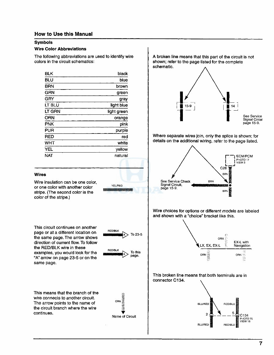
How to Use this Manual Symbols Wire Color Abbreviations The following abbreviations are used to identify wire colors in the circuit schematics: BLK black BLU blue BRN brown GRN green GRY gray LT BLU light blue LT GRN light green ORN orange PNK pink PUR purple RED red WHT white YEL yellow NAT natural Wires Wire insulation can be one color, or one color with another color stripe. (The second color is the color of the stripe.) YEL/RED This circuit continues on another page or at a different location on the same page. The arrow shows direction of current flow. To follow the RED/BLK wire in these examples, you would look for the "A" arrow on page 23-5 or on the same page. RED/BLK A> To 23-5 To this page. This means that the branch of the wire connects to another circuit. The arrow points to the name of the circuit branch where the wire continues. ORN Name of Circuit A broken line means that this part of the circuit is not shown; refer to the page listed for the complete schematic. See Service Signal Circui page 15-9. Where separate wires join, only the splice is shown; for details on the additional wiring, refer to the page listed. [—I ECM/PCM • PHOTO 17 I VIEW 3 I I C28 w See Service Check Signal Circuit, ^ < page 15-9. Wire choices for options or different models are labeled and shown with a "choice" bracket like this. ORN J i LX, EX, EX-L EX-L with Navigation ORN This broken line means that both terminals are in connector C134. BLU/RED RED/BLU 7
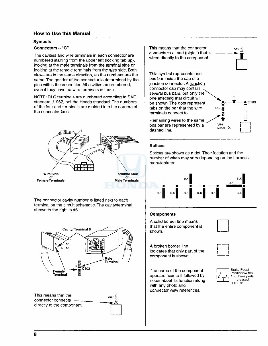
Mow to Use this Manual Symbols Connectors - "C" The cavities and wire terminals in each connector are numbered starting from the upper left (locking tab up), looking at the male terminals from the terminal side or looking at the female terminals from the wire side. Both views are in the same direction, so the numbers are the same. The gender of the connector is determined by the pins within the connector. All cavities are numbered, even if they have no wire terminals in them. NOTE: DLC terminals are numbered according to SAE standard J1962, not the Honda standard. The numbers of the four end terminals are molded into the corners of the connector face. Wire Side of Female Terminals Terminal Side of Male Terminals The connector cavity number is listed next to each terminal on the circuit schematic. The cavity/terminal shown to the right is #6. Cavity/Terminal 6 This means that the connector connects directly to the component. This means that the connector connects to a lead (pigtail) that is wired directly to the component. This symbol represents one bus bar inside the cap of a junction connector. A junction connector cap may contain several bus bars, but only the one affecting that circuit will be shown. The dots represent tabs on the bar that the wire terminals connect to. Remaining wires to the same bus bar are represented by a dashed line. GRY -# C103 if See page 10. J Splices Splices are shown as a dot. Their location and the number of wires may vary depending on the harness manufacturer. BLK • • • I BLK Components A solid border line means that the entire component is shown. A broken border line indicates that only part of the component is shown. The name of the component appears next to it followed by notes about its function along with any photo and connector view references. i Brake Pedal PositionSwitch 1 = Brake pedal pressed. PHOTO 98 8
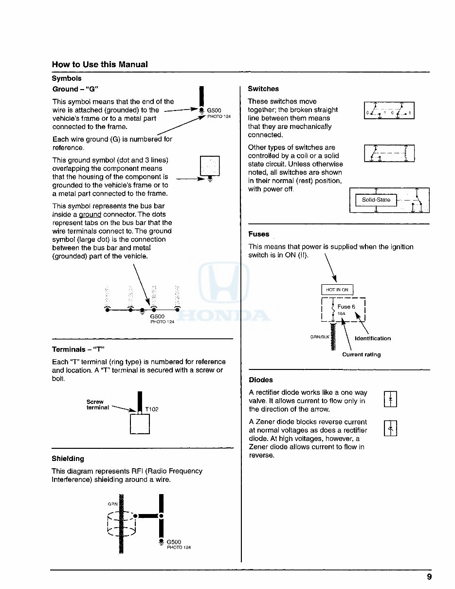
How to Use this Manual Symbols Ground - "G" This symbol means that the end of the wire is attached (grounded) to the vehicle's frame or to a metal part connected to the frame. Each wire ground (G) is numbered for reference. This ground symbol (dot and 3 lines) overlapping the component means that the housing of the component is grounded to the vehicle's frame or to a metal part connected to the frame. This symbol represents the bus bar inside a ground connector. The dots represent tabs on the bus bar that the wire terminals connect to. The ground symbol (large dot) is the connection between the bus bar and metal (grounded) part of the vehicle. i Terminals - "T" Each "T" terminal (ring type) is numbered for reference and location. A "T" terminal is secured with a screw or bolt. Screw terminal J t102 Shielding This diagram represents RFI (Radio Frequency Interference) shielding around a wire. i m I # G500 PHOTO 124 Switches These switches move together; the broken straight line between them means that they are mechanically connected. Other types of switches are controlled by a coil or a solid state circuit. Unless otherwise noted, all switches are shown in their normal (rest) position, with power off. T Solid-State . _ JL Fuses This means that power is supplied when the ignition switch is in ON (II). Identification Current rating Diodes A rectifier diode works like a one way valve. It allows current to flow only in the direction of the arrow. A Zener diode blocks reverse current at normal voltages as does a rectifier diode. At high voltages, however, a Zener diode allows current to flow in reverse.
If you are in need of a repair manual for your 2010 Honda Insight, look no further. This comprehensive manual is designed to assist both professional mechanics and DIY enthusiasts in performing a wide range of repairs and maintenance tasks on the Honda Insight.
In the past, obtaining service information required purchasing traditional paper manuals at a higher cost. However, this digital repair manual provides a more affordable and convenient alternative, allowing easy access to essential information.
Whether you are tackling brake repairs, suspension component replacements, engine troubleshooting, or standard maintenance procedures, this manual has you covered. It contains detailed instructions for addressing various vehicle systems, including brakes, engine, suspension, steering, drivetrain, electrical, heating, and air conditioning.
By utilizing this manual, you can save a significant amount of money on repair costs. Professional mechanics often charge high fees for their services, making DIY repairs a cost-effective option. This 2010 Honda Insight repair manual is user-friendly and compatible with Windows, Mac computers, smartphones, and tablets, ensuring accessibility across different devices.