

2011 Honda Element Repair Manual
What's Included?
Fast Download Speeds
Online & Offline Access
Access PDF Contents & Bookmarks
Full Search Facility
Print one or all pages of your manual

2007-2011
HONDA ELEMENT
SERVICE AND REPAIR MANUAL
ENGINE PERFORMANCE
Advanced Diagnostics - Element
DTC P0011 (56): ADVANCED DIAGNOSTICS
DTC P0011: VARIABLE VALVE TIMING CONTROL (VTC) SYSTEM MALFUNCTION
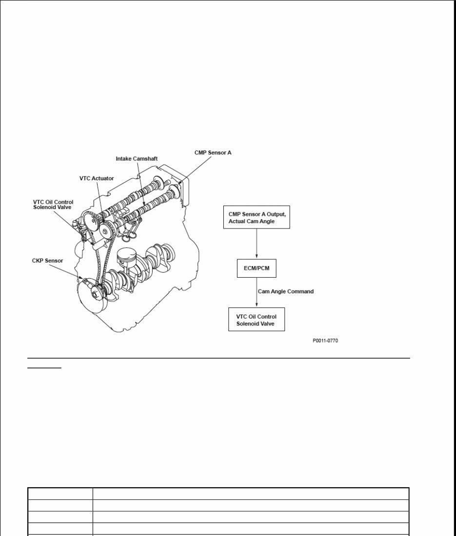
Fig. 1: Identifying Variable Valve Timing Control (VTC) System Consisting Components With Flow
Diagram
General Description
The variable valve timing control (VTC) system controls the timing of the intake camshaft. It uses hydraulic
pressure to operate the VTC actuator so the valve timing is optimized depending on driving conditions. The
engine control module (ECM)/powertrain control module (PCM) monitors the phase control command and the
actual timing of the camshaft by using camshaft position (CMP) sensor A. If the phase difference between them
is excessive for a certain time period, a malfunction is detected and a DTC is stored.
Monitor Execution, Sequence, Duration, DTC Type, OBD Status
MONITOR DESCRIPTION
Execution Continuous
Sequence None
Duration 15 seconds or more
DTC Type Two drive cycles, MIL ON

Enable Conditions
ENABLE CONDITIONS
Malfunction Threshold
The timing difference between the timing control command and the actual timing of the camshaft is 5.0 ° or
more for at least 15 seconds.
Confirmation Procedure with the HDS
Do the VTC TEST in the INSPECTION MENU of the HDS.
Driving Pattern
OBD Status PASSED/FAILED/NOT COMPLETED (STILL TESTING)
Condition Minimum Maximum
Elapsed time after
starting the engine
10 seconds -
Engine coolant
temperature
23 °F (-
5 °C)
(1)
158 °F (70 °C)
-
-13 °F
(-25 °
C)
(1)
185 °F (85 °C)
Engine speed
203 °F
(95 °C)
(2)
800 rpm
-
227 °F
(107 °
C)
(2)
1,600 rpm
Elapsed TDC
revolutions
25 °F (-
4 °C)
(1)
Per 0 revolutions
-
-13 °F
(-25 °
C)
(1)
Per 23,500 revolutions
Battery voltage 10.5 V -
No active DTCs
P0010, P0107, P0108, P0112, P0113, P0117, P0118, P0122, P0123, P0222,
P0223, P0335, P0339, P0340, P0341, P0344, P1009, P1128, P1129, P2101,
P2118, P2122, P2123, P2127, P2128, P2135, P2138, P2176, P2227, P2228,
P2229, P2646, P2647, P2648, P2649
(1)
Depending on initial engine coolant temperature.
(2)
Depending on engine coolant temperature.
1. Start the engine. Hold the engine speed at 3,000 rpm without load (in Park or neutral) until the radiator
fan comes on.
2. Drive the vehicle at a steady speed between 25 - 75 mph (40 - 120 km/h) for at least 15 seconds.
Drive the vehicle in this manner only if the traffic regulations and ambient conditions allow.
Diagnosis Details
Conditions for illuminating the MIL
When a malfunction is detected during the first drive cycle, a Temporary DTC is stored in the ECM/PCM
memory. If the malfunction recurs during the next (second) drive cycle, the MIL comes on and the DTC and the
freeze frame data are stored.
Conditions for clearing the MIL
The MIL will be cleared if the malfunction does not recur during three consecutive trips in which the diagnostic
runs.
The MIL, the DTC, the Temporary DTC, and the freeze frame data can be cleared by using the scan tool Clear
command or by disconnecting the battery.
DTC P0101 (50): ADVANCED DIAGNOSTICS
DTC P0101: MASS AIRFLOW (MAF) SENSOR CIRCUIT RANGE/PERFORMANCE PROBLEM
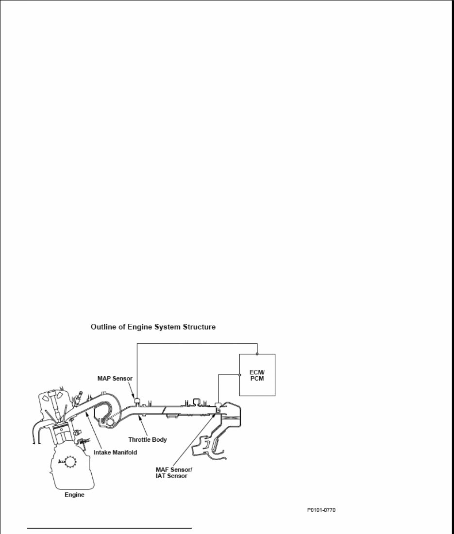
Fig. 2: Outline Of Engine System Structure
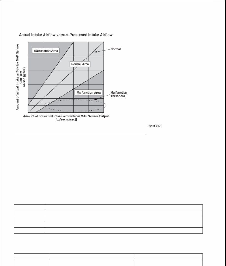
Fig. 3: Actual Intake Airflow Versus Presumed Intake Airflow Graph
General Description
The mass airflow (MAF) sensor directly measures the amount of intake airflow into the engine, and the engine
control module (ECM)/powertrain control module (PCM) controls the fuel injection based on the measured
value. The manifold absolute pressure (MAP) sensor measures the intake manifold pressure and the ECM/PCM
calculates the amount of intake airflow from the MAP sensor output and the engine revolutions. The ECM/PCM
compares the MAF sensor output (amount of intake airflow) and the amount of intake airflow calculated from
MAP sensor output. If their difference is too large (in the malfunction area), the ECM/PCM detects a
malfunction and a DTC is stored.
Monitor Execution, Sequence, Duration, DTC Type, OBD Status
MONITOR DESCRIPTION
Enable Conditions
ENABLE CONDITIONS
Execution Once per driving cycle
Sequence None
Duration 5 seconds or more
DTC Type Two drive cycles, MIL ON
OBD Status PASSED/FAILED/NOT COMPLETED (STILL TESTING)
Condition Minimum Maximum
Elapsed time after

Malfunction Threshold
The difference between the amount of intake air measured by the MAF sensor and the amount of intake air
calculated from the MAP sensor output is out of the normal area for at least 5 seconds.
Driving Pattern
1. Start the engine. Hold the engine speed at 3,000 rpm without load (in Park or neutral) until the radiator
fan comes on.
2. Let the engine idle for at least 5 seconds.
Diagnosis Details
Conditions for illuminating the MIL
When a malfunction is detected during the first drive cycle, a Temporary DTC is stored in the ECM/PCM
memory. If the malfunction recurs during the next (second) drive cycle, the MIL comes on and the DTC and the
freeze frame data are stored.
Conditions for clearing the MIL
The MIL will be cleared if the malfunction does not recur during three consecutive trips in which the diagnostic
runs.
The MIL, the DTC, the Temporary DTC, and the freeze frame data can be cleared by using the scan tool Clear
command or by disconnecting the battery.
DTC P0102 (50): ADVANCED DIAGNOSTICS
DTC P0102: MASS AIRFLOW (MAF) SENSOR CIRCUIT LOW VOLTAGE
starting the engine 3 seconds -
Engine coolant
temperature
156 °F (69 °C) -
Engine speed 600 rpm 5,700 rpm
No active DTCs
P0102, P0103, P0107, P0108, P0112, P0113, P0117, P0118, P0171, P0172, P0300,
P0301, P0302, P0303, P0304, P0335, P0339, P0340, P0341, P0344, P0443, P0496,
P0497, P0506, P0507, P1128, P1129, P145C, P2646, P2647, P2648, P2649
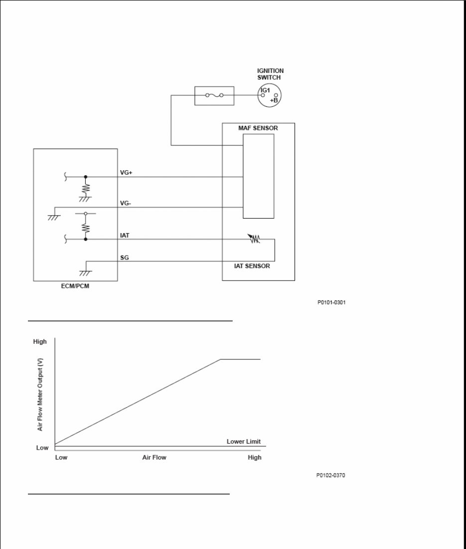
Fig. 4: Mass Airflow (MAF) Sensor Circuit Diagram
Fig. 5: Mass Air Flow Meter Output Voltage Graph
General Description
The mass airflow (MAF) sensor is attached to the intake air passage, and it measures the amount of intake
airflow. The MAF sensor is a hot wire airflow meter. The airflow cools the electrically heated wire that is
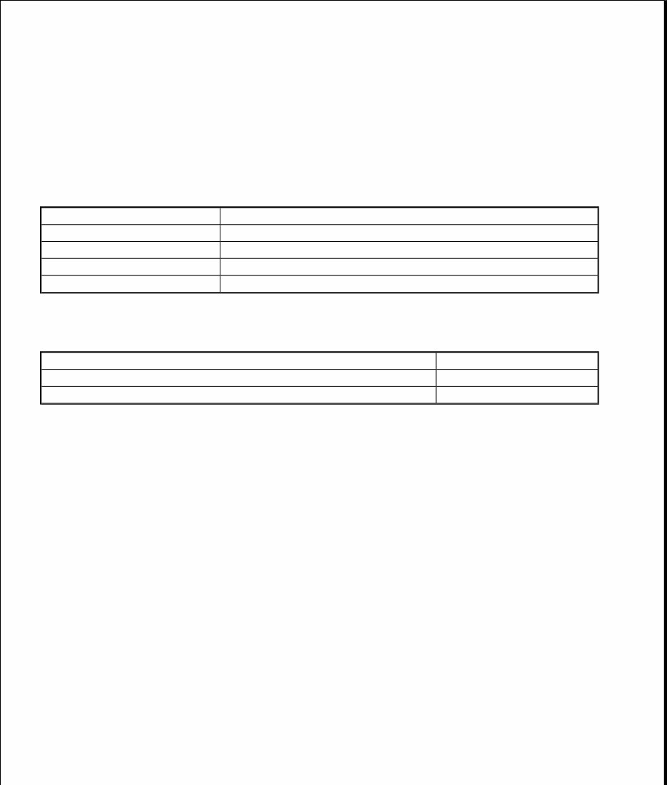
mounted in the air passage. The engine control module (ECM)/powertrain control module (PCM) determines
the amount of intake airflow by detecting the current that is required to keep the hot wire at a constant
temperature. The lower limit of the MAF sensor output is specified. If the output is below that limit, the
ECM/PCM detects a malfunction and stores a DTC.
Monitor Execution, Sequence, Duration, DTC Type, OBD Status
MONITOR DESCRIPTION
Enable Conditions
ENABLE CONDITIONS
Malfunction Threshold
The input voltage from the MAF sensor is 0.1 V or less for at least 2 seconds.
Diagnosis Details
Conditions for illuminating the MIL
When a malfunction is detected, the MIL comes on and the DTC and the freeze frame data are stored in the
ECM/PCM memory.
Conditions for clearing the MIL
The MIL will be cleared if the malfunction does not recur during three consecutive trips in which the diagnostic
runs.
The MIL, the DTC, and the freeze frame data can be cleared by using the scan tool Clear command or by
disconnecting the battery.
DTC P0103 (50): ADVANCED DIAGNOSTICS
DTC P0103: MASS AIRFLOW (MAF) SENSOR CIRCUIT HIGH VOLTAGE
Execution Continuous
Sequence None
Duration 2 seconds or more
DTC Type One drive cycle, MIL ON
OBD Status N/A
Condition
Ignition switch ON
No active DTCs P0103
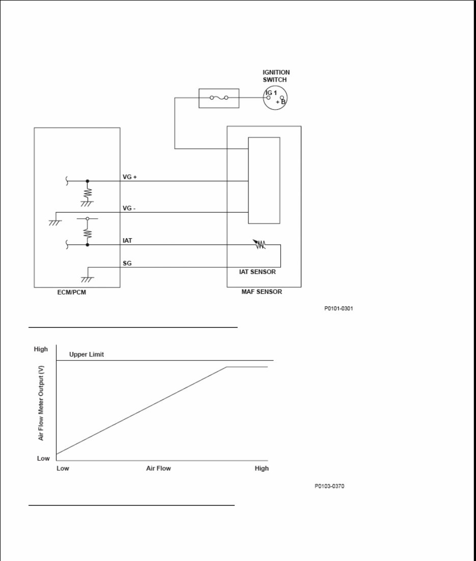
Fig. 6: Mass Airflow (MAF) Sensor Circuit Diagram
Fig. 7: Mass Air Flow Meter Output Voltage Graph
General Description
The mass airflow (MAF) sensor is attached to the intake air passage, and it measures the amount of intake
airflow. The MAF sensor is a hot wire airflow meter. The airflow cools the electrically heated wire that is

mounted in the air passage. The engine control module (ECM)/powertrain control module (PCM) determines
the amount of intake airflow by detecting the current that is required to keep the hot wire at a constant
temperature. The upper limit of the MAF sensor output is specified. If the output is above that limit, the
ECM/PCM detects a malfunction and stores a DTC.
Monitor Execution, Sequence, Duration, DTC Type, OBD Status
MONITOR DESCRIPTION
Enable Conditions
ENABLE CONDITIONS
Malfunction Threshold
The input voltage from the MAF sensor is 4.89 V or more for at least 2 seconds.
Diagnosis Details
Conditions for illuminating the MIL
When a malfunction is detected, the MIL comes on and the DTC and the freeze frame data are stored in the
ECM/PCM memory.
Conditions for clearing the MIL
The MIL will be cleared if the malfunction does not recur during three consecutive trips in which the diagnostic
runs.
The MIL, the DTC, and the freeze frame data can be cleared by using the scan tool Clear command or by
disconnecting the battery.
DTC P0107 (3): ADVANCED DIAGNOSTICS
DTC P0107: MANIFOLD ABSOLUTE PRESSURE (MAP) SENSOR CIRCUIT LOW VOLTAGE
Execution Continuous
Sequence None
Duration 2 seconds or more
DTC Type One drive cycle, MIL ON
OBD Status N/A
Condition
Ignition switch ON
No active DTCs P0102
You're Reading a Preview
What's Included?
Fast Download Speeds
Online & Offline Access
Access PDF Contents & Bookmarks
Full Search Facility
Print one or all pages of your manual
$37.99
Viewed 61 Times Today


Secure transaction
What's Included?
Fast Download Speeds
Online & Offline Access
Access PDF Contents & Bookmarks
Full Search Facility
Print one or all pages of your manual
$37.99
The Repair Manual for the Honda Element 2011 is a comprehensive guide designed to assist in the maintenance and repair of this vehicle model. This manual is essential for technicians, mechanics, and DIY enthusiasts who wish to perform Repair procedures accurately and efficiently.
Key features of the Honda Element 2011 Repair Manual include:
- Detailed specifications and performance data
- Step-by-step instructions for routine maintenance tasks
- Comprehensive diagrams and photos for clarity
- Diagnostic procedures for troubleshooting various components
- Information on engine overhaul and transmission repair
- Guidance on electrical systems including wiring diagrams
- Procedures for brake system maintenance and repair
- Details on suspension and steering system servicing
- Instructions for HVAC (Heating, Ventilation, and Air Conditioning) system repairs
This Repair manual is an invaluable resource that ensures the longevity and reliable performance of your Honda Element 2011. With its detailed content, it aids in the accurate diagnosis of issues, efficient repairs, and regular maintenance to keep your vehicle in optimal condition.


