

2014 Honda CR-Z Repair Manual
What's Included?
Fast Download Speeds
Online & Offline Access
Access PDF Contents & Bookmarks
Full Search Facility
Print one or all pages of your manual
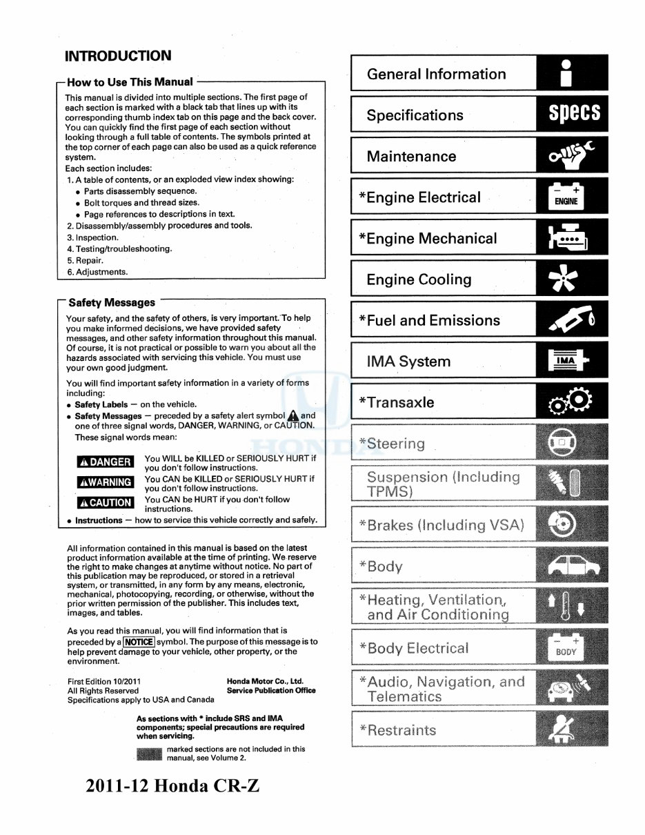
INTRODUCTION
- How to Use This Manual ---------------------------------
This manual i s divided into multiple sections. The first page of
each section is marked with a black tab that lines up with its
corresponding thumb index tab on this page and the back cover.
You can quickly find the first page of each section without
looking through a full table of contents. The symbols printed at
the top corner of each page can also be used as a quick reference
system.
Each section includes:
1. A table of contents, or an exploded view index showing:
• Parts disassembly sequence.
• Bolt torques and thread sizes.
• Page references to descriptions in text.
2. Disassembly/assembly procedures and tools.
3. Inspection.
4. Testing/troubleshooting.
5. Repair.
6. Adjustments.
~Safety Messages
Your safety, and the safety of others, is very important. To help
you make informed decisions, we have provided safety
messages, and other safety information throughout this manual.
Of course, it is not practical or possible to warn you about all the
hazards associated with servicing this vehicle. You must use
your own good judgment.
You will find important safety information in a variety of forms
including:
• Safety Labels —on the vehicle.
• Safety Messages —preceded by a safety alert symbol A and
one of three signal words, DANGER, WARNING, or CAUTION.
These signal words mean:
You WILL be KILLED or SERIOUSLY HURT if
you don't follow instructions.
You CAN be KILLED or SERIOUSLY HURT if
you don't follow instructions.
You CAN be HURT if you don't follow
instructions.
Instructions — howto service this vehicle correctly and safely.
▲ DANGER
AWARN I NG
A CAUTION
All information contained in this manual is based on the latest
product information available at the time of printing. We reserve
the right to make changes at anytime without notice. No part of
this publication may be reproduced, or stored in a retrieval
system, or transmitted, in any form by any means, electronic,
mechanical, photocopying, recording, or otherwise, without the
prior written permission of the publisher. This includes text,
images, and tables.
As you read this manual, you will find information that is
preceded by a I NOTICE Isymbol. The purpose of this message is to
help prevent damage to your vehicle, other property, or the
environment.
First Edition 10/2011
All Rights Reserved
Specifications apply to USA and Canada
Honda Motor Co., Ltd.
Service Publication Office
As sections with * include SRS and IMA
components; special precautions are required
when servicing.
* w#**' marked sections are not included in this
manual, see Volume 2.
General Information
Specifications specs
Maintenance
^Engine Electrical
*Engine Mechanical
Engine Cooling
•k
*Fuel and Emissions
IMA System | | IMA^ | j
*Transaxle
*
Steering
[«□ i
Suspension {Including
TPMS)
*
Brakes (Including VSA)
Body
^Heating, Ventilation,
and Air € osi<Ii t ; ■ oning
*
Body Electrical
*Audio, Navigation,, and
Telematics ‘
* Restraints
2011-12 Honda CR-Z
SUPPLEMENTAL RESTRAINT SYSTEM (SRS)
The CR-Z SRS includes a driver's airbag in the steering wheel hub, a front passenger's airbag in the dashboard
above the glove box, seat belt tensioners in the front seat belt retractors, side curtain airbags in the sides of the
roof, and side airbags in the front seat-backs. Information necessary to safely service the SRS is included in this
Service Manual. Items marked with an asterisk (*) on the contents page include or are located near SRS
components. Servicing, disassembling, or replacing these items requires special precautions and tools, and
should be done by an authorized Honda dealer.
• To avoid rendering the SRS inoperative, which could lead to personal injury or death in the event of a severe
frontal or side collision, all SRS service work should be done by an authorized Honda dealer.
• Improper service procedures, including incorrect removal and installation of the SRS, could lead to personal
injury caused by unintentional deployment of the airbags, side airbags, side curtain airbags, and/or seat belt
tensioners.
• Do not bump or impact the SRS unit, front impact sensors, or side impact sensors, especially when the
ignition switch is ON (II), or for at least 3 minutes after the ignition switch is turned to LOCK (0); otherwise, the
system may fail in a collision, or the airbags may deploy.
• SRS electrical connectors are identified by yellow color coding. Related components are located in the
steering column, center console, dashboard, in the dashboard above the glove box, in the front seats, in the
roof side, and around the floor. Do not use electrical test equipment on these circuits.
• INTEGRATED MOTOR ASSIST (IMA) SYSTEM' ■
IMA components are located in this area. The IMA is a high-voltage system. The high voltage cables and their
covers are identified by orange coloring. The safety labels are attached to high voltage and other related parts
(see page 1-7). You must be familiar with the IMA system before working around it. Make sure you have read the
Service Precautions in the IMA section before doing repairs or service (see page 12-3).
General Information
Chassis and Paint Codes
'11 Model. .............................. ...................... ................ 1-2
'12 Model ..... ...................................... ......... .......... ...... 1-4
Identification Number Locations....... ...... ................. ... .1-6
Danger/Warning/Caution Label Locations................... 1-7
Under-Hood Emission Control Label .................... . 1-9
Lift and Support Points .................................................... 1-10
Towing ............... .................................................................. 1-11
Parts Marking ................................................. . 1—13
Service Precautions....................................... .................. 1-13
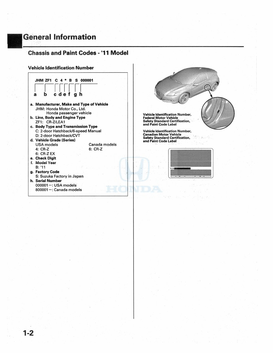
Chassis and Paint Codes - '11 Model
Vehicle Identification Number
jhm zfi c 4 * b s mmm
a b c d e f g h
a. Manufacturer, Make and Type of Vehicle
JHM: Honda Motor Go., Ltd.
Honda passenger vehicle
b. Line, Body and Engine Type
ZFI: CR-Z/LEA1
c. Body Type and Transmission Type
C: 2-door Hatchback/6-speed Manual
D: 2-door Hatchback/CVT
d. Vehicle Grade (Series)
USA models Canada models
4: CR-Z 6: CR-Z
6: CR-Z EX
e. Check Digit
f. Model Year
B: '11
g. Factory Code
S: Suzuka Factory in Japan
h. Serial Number
000001 USA models
800001 —: Canada models
f
Vehicle Identification Number,
Federal Motor Vehicle
Safety Standard Certification,
and Paint Code Label
Vehicle Identification Number,
Canadian Motor Vehicle
Safety Standard Certification,
and Paint Code Label

m
Engine Number
LEA1 -1000001
a b
a. Engine Type
LEA1:1.5 L SOHC i-VTEC Sequential Multiport
Fuel-injected engine
b. Serial Number
Motor Number
MF6- - 1000001
a b
a. Motor Type
MF6: DC brushless-3 phases
b. Serial Number
Transmission Number
STXM - 1000001
a b
a. Transmission Type
STXM; 6-speed Manual
STYA; CVT
b. Serial Number
Paint Code
Code Color USA
models
Canada
models
NH-624P Premium White Pearl o O
NH-642M Storm Silver Metallic o O
NH-731P Crystal Black Pearl o
BG-57P North Shore Blue
Pearl
o o
R-81 Milano Red o o
m
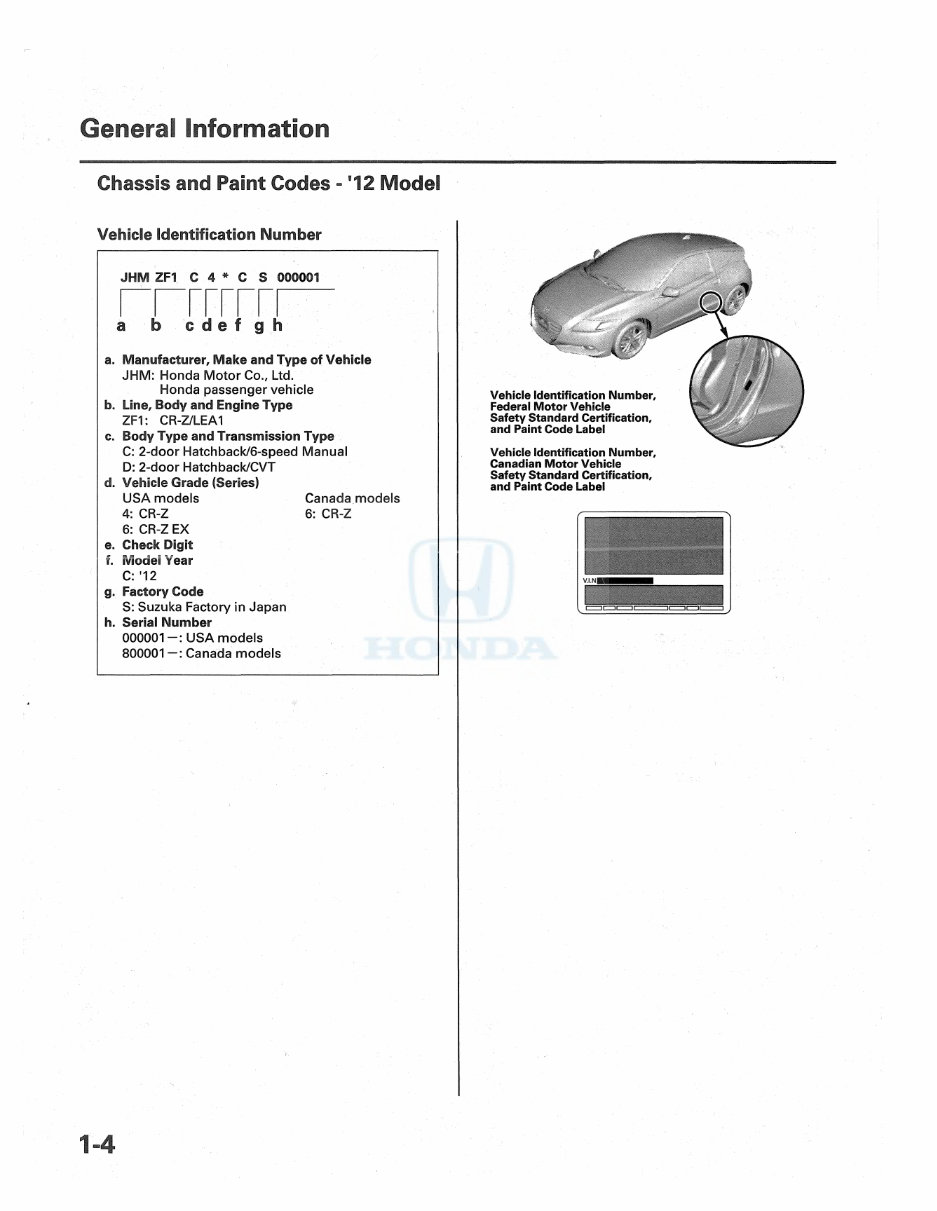
Chassis and Paint Codes - '12 Model
Vehicle Identification Number
JHM ZFI C 4 * C S 000001
b.
c.
i b c def g h
Manufacturer, Make and Type of Vehicle
JHM: Honda Motor Co., Ltd.
Honda passenger vehicle
Line, Body and Engine Type
ZF1: CR-Z/LEA1
Body Type and Transmission Type
C: 2-door Hatch back/6-speed Manual
D: 2-door Hatchback/CVT
d. Vehicle Grade (Series)
USA models Canada models
4: CR-Z 6: CR-Z
6: CR-Z EX
e. Check Digit
f. Model Year
C: '12
g. Factory Code
S: Suzuka Factory in Japan
h. Serial Number
0 0 0 0 0 1 USA models
800001 Canada models
Canadian Motor Vehicle
Safety Standard Certification,
and Paint Code Label
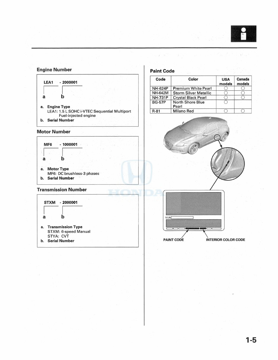
Engine Number
Paint Code
LEA1 - 2000001
a b
a. Engine Type
LEA1: 1.5 L SOHC i-VTEC Sequential Multiport
Fuel-injected engine
b. Serial Number
Motor Number
MF6 - 1000001
a b
a. Motor Type
MF6: DC brushless-3 phases
b. Serial Number
Transmission Number
STXM - 2000001
a b
a. Transmission Type
STXM: 6-speed Manual
STYA: CVT
b. Serial Number
Code Color USA
models
Canada
models
NH-624P Premium White Pearl O O
NH-642M Storm Silver Metallic O O
NH-731P Crystal Black Pearl o o
BG-57P North Shore Blue
Pearl
o
R-81 Milano Red o o
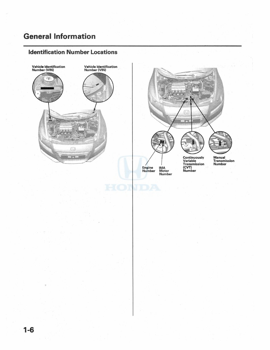
Identification Number Locations
Vehicle Identification Vehicle Identification
Number (VIN) Number (VIN)
Engine IMA (CVT)
Number Motor Number
Number
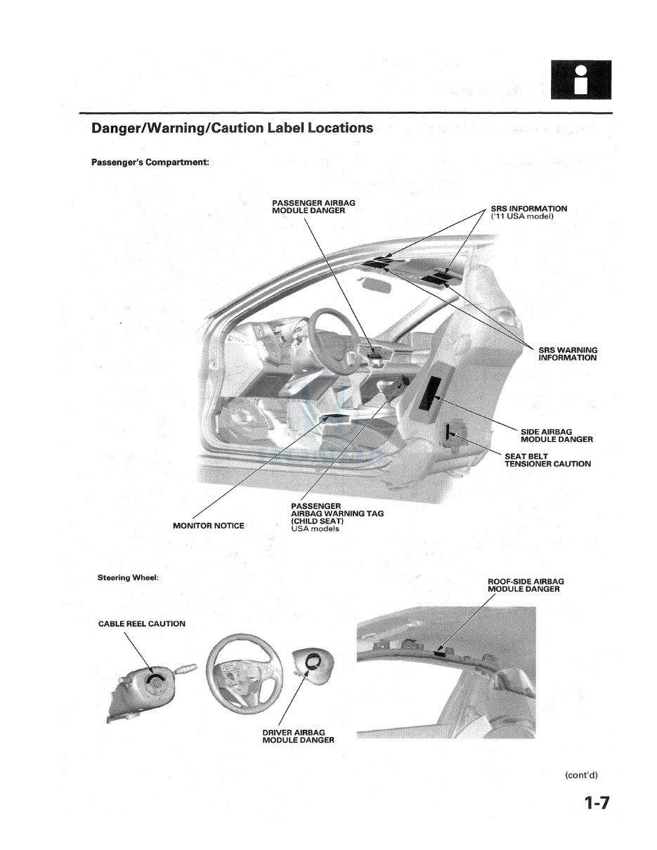
Danger/Warning/Caution Label Locations
Passenger's Compartment:
Steering Wheel:
ROOF-SIDE AIRBAG
MODULE DANGER
GABLE REEL CAUTION
DRIVER AIRBAG
MODULE DANGER
(cont'd)
General Information
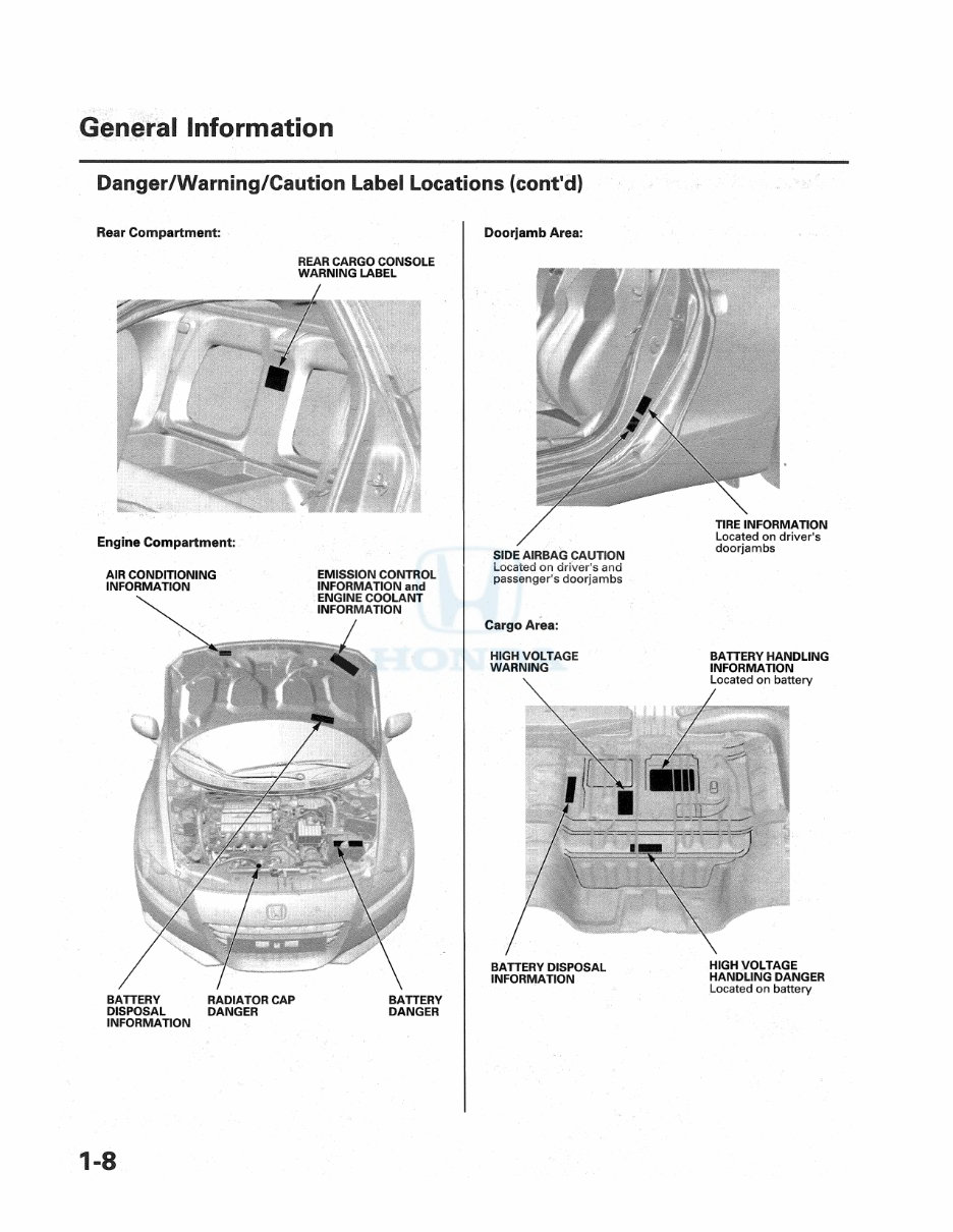
Danger/Warning/Caution Label Locations (cont'd)
Rear Compartment;
REAR CARGO CONSOLE
WARNING LABEL
Engine Compartment:
AIR CONDITIONING
INFORMATION
EMISSION CONTROL
INFORMATION and
ENGINE COOLANT
INFORMATION
DISPOSAL
INFORMATION
DANGER DANGER
Doorjamb Area:
passenger's doorjambs
Cargo Area:
HIGH VOLTAGE
WARNING
BATTERY HANDLING
INFORMATION
BATTERY DISPOSAL
INFORMATION
HIGH VOLTAGE
HANDLING DANGER
Located on battery
You're Reading a Preview
What's Included?
Fast Download Speeds
Online & Offline Access
Access PDF Contents & Bookmarks
Full Search Facility
Print one or all pages of your manual
$47.99
Viewed 38 Times Today


Secure transaction
What's Included?
Fast Download Speeds
Online & Offline Access
Access PDF Contents & Bookmarks
Full Search Facility
Print one or all pages of your manual
$47.99
The Repair manual for the Honda CR-Z 2014 provides comprehensive information to assist owners and technicians in performing maintenance, repairs, and troubleshooting. This manual is an essential resource for ensuring the vehicle operates efficiently and safely. The manual includes detailed descriptions, illustrations, and step-by-step instructions covering various aspects of the vehicle.
Key sections of the Repair manual include:
- General Information
- Specifications
- Maintenance
- Engine Electrical
- Engine Mechanical
- Cooling System
- Fuel and Emissions
- Transaxle
- Steering
- Suspension
- Brakes
- Body
- Electrical
- HVAC (Heating, Ventilation, and Air Conditioning)
Each section is designed to provide in-depth coverage of the respective systems and components, ensuring users can confidently perform necessary tasks. Whether you are a professional technician or a DIY enthusiast, this manual is a valuable tool for keeping your Honda CR-Z 2014 in top condition.


