

INT RO DUCTION
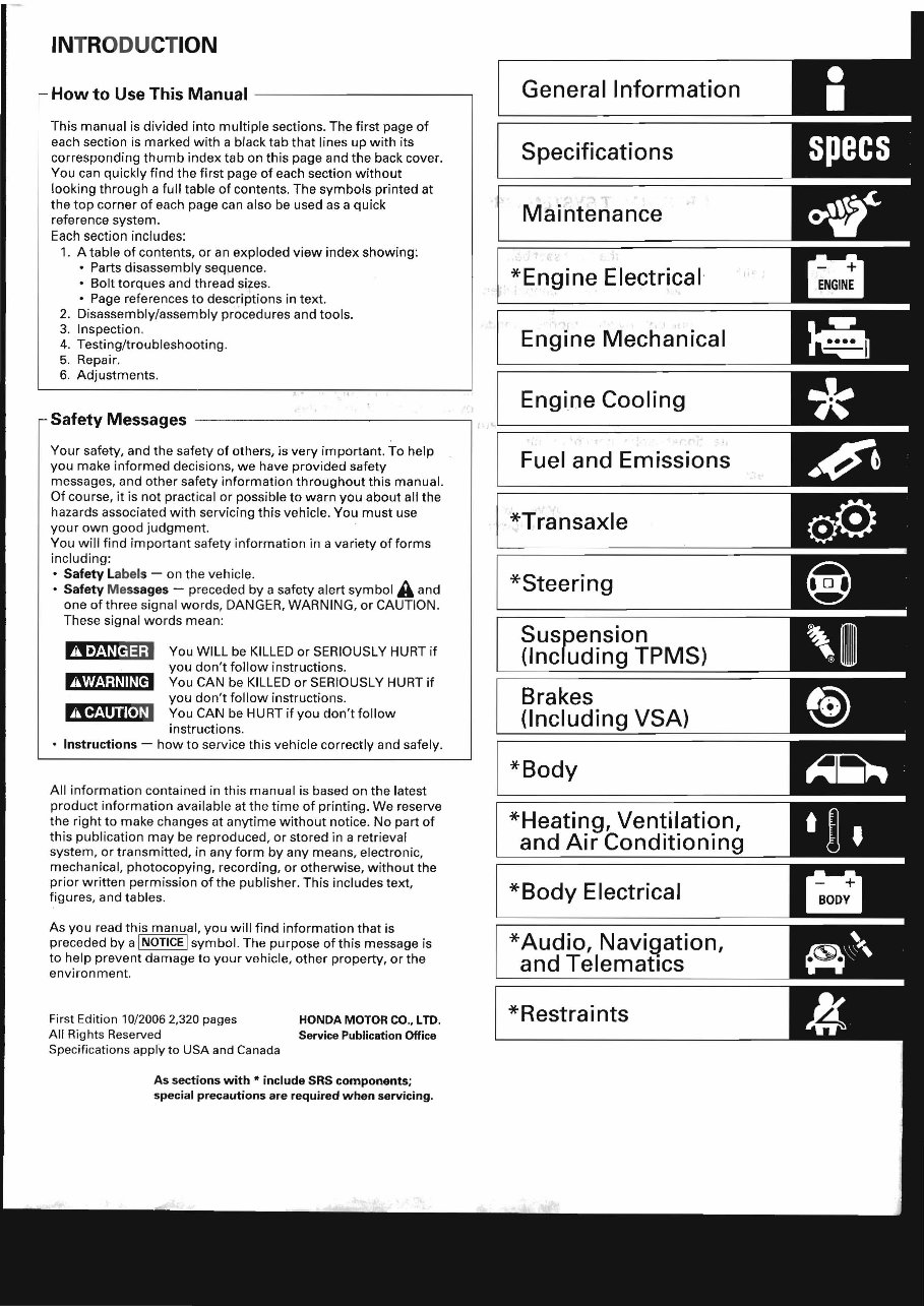
How to Use This Manual -------------,
This manual is divided into multiple sections. The first page of
each section is marked with a black tab that lines up with its
corresponding thumb index tab on this page and the back cover.
You can quickly find the first page of each section without
looking through a full table of contents. The symbols printed at
the top corner of each page can also be used as a quick
reference system.
Each section includes:
1. A table of contents, or an exploded view index showing:
• Parts disassembly sequence.
• Bolt torques and thread sizes.
• Page references to descriptions in text .
2. Disassembly/assembly procedures and tools.
3. Inspection.
4. Testing/troubleshooting.
5. Repair.
6. Adjustments.
Safety Messages ----------------,
Your safety, and the safety of others, is very important. To help
you make informed decisions, we have provided safety
messages, and other safety information throughout this manual.
Of course, it is not practical or possible to warn you about all the
hazards associated with servicing this vehicle. You must use
your own good judgment.
You will find important safety information in a variety of forms
including:
• Safety Labels - on the vehicle.
• Safety Messages - preceded by a safety alert symbol A and
one of three signal words, DANGER, WARNING, or CAUTION .
These signal words mean:
You WILL be KILLED or SERIOUSLY HURT if
you don't follow instructions.
m!J!l!1jl W HD You CAN be KILLED or SERIOUSLY HURT if
you don't follow instructions.
tlJIf!1IW.,U You CAN be HURT if you don't follow
instructions.
• Instructions - how to service this vehicle correctly and safely.
All information contained in this manual is based on the latest
product information available at the time of printing. We reserve
the right to make changes at anytime without notice. No part of
this publication may be reproduced, or stored in a retrieval
system, or transmitted, in any form by any means, electronic,
mechanical, photocopying, recording, or otherwise, without the
prior written permission ofthe publisher. This includes text,
figures, and tables.
As you read this manual, you will find information that is
preceded by a INOTICE I symbol. The purpose of this message is
to help prevent damage to your vehicle, other property, or the
environment .
First Edition 10/20062,320 pages HONDA MOTOR CO., LID.
All Rights Reserved Service Publication Office
Specifications apply to USA and Canada
As sections with * include SRS components;
special precautions are required when servicing.
General Information
Specifications
Maintenance
*Engine Electrical
I
Engine Mechanical
Engine Cooling
Fuel and Emissions
*Transaxle
*Steering
Suspension
(Including TPMS)
Brakes
(Including VSA)
*Body
*Heating, Ventilation,
and Air Conditionin
*Body Electrical
* Audio, Navigation,
and Telematics
*Restraints
SUPPLEMENTAL RESTRAINT (SRS)
The CR-V SRS includes a driver's airbag in the steering wheel hub, a passenger's airbag in the dashboard above the
glove box, seat belt tensioners in the front seat belt retractors, seat belt buckle tensioners in the front seat belt buckles,
side curtain airbags in the sides of the roof, and side airbags in the front seat-backs. Information necessary to safely
service the SRS is included in this Service Manual. Items marked with an asterisk ( * ) on the contents page include or
are located near SRS components. Servicing, disassembling, or replacing these items require special precautions and
tools, and should be done only by an authorized Honda dealer.
• To avoid rendering the SRS inoperative, which could lead to personal injury or death in the event of a severe frontal
or side collision, all SRS service work should be done by an authorized Honda dealer.
• Improper service procedures, including incorrect removal and installation of the SRS, could lead to personal injury
caused by unintentional deployment of the airbags and/or side airbags.
• Do not bump or impact the SRS unit, front impact sensors, or side impact sensors when the ignition switch is ON (II),
/! or for at least 3 minutes after the ignition switch is turned OFF; otherwise, the system may fail in a collision, or the
airbags may deploy.
• SRS electrical connectors are identified by yellow color coding. Related components are located in the steering
column, front console, dashboard, dashboard lower panel, in the dashboard above the glove box, in the front seats,
in the roof side, and around the floor. Do not use electrical test equipment on these circuits.
J
General Information
Chassis and Paint Codes .................................. 1-2
Identification Number Locations ......... ........... 1-3
Danger/Warning/Caution Label Locations .... 1-4
Under-hood Emission Control Label ............... 1-6
Lift and Support Points .................................... 1-7
Towing .............................................................. 1-8
Parts Marking .................................................... 1-10
Precautions for Real-time 4WD
(Four-wheel Drive) ........................................ 1-10
General Information
Chassis and Paint Codes
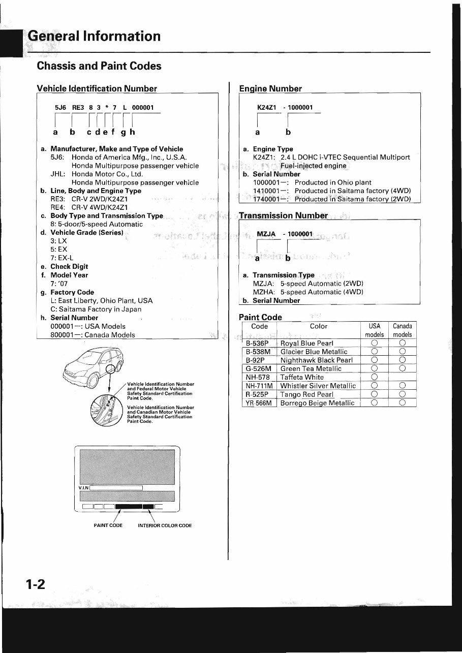
Vehicle Identification Number
5J6 RE3 8 3 * 7 L 000001
IIIIIIII
a b cdefgh
a. Manufacturer, Make and Type of Vehicle
5J6: Honda of America Mfg., Inc., U.S.A.
Honda Multipurpose passenger vehicle
JHL: Honda Motor Co., Ltd.
Honda Multipurpose passenger vehicle
b. Line, Body and Engine Type
RE3: CR-V 2WD/K24Z1 . .,
RE4: CR-V 4WD/K24Z1
c. Body Type and Transmission Type
8: 5-door/5-speed Automatic
d. Vehicle Grade (Series)
3: LX
5: EX
7: EX·L
e. Check Digit
f. Model Year
7: '07
g. Factory Code
, r'
L: East Liberty, Ohio Plant, USA
C: Saitama Factory in Japan
h. Serial Number
1-2
000001-: USA Models
800001- : Canada Models
v .I.N I
CJDCJ
1
PAINT CODE
Vehicle Ident ific a tion Number
and Federal Motor Vehicle
Safety Standard Certification
Pa int Code.
Vehicle Identificat ion Number
and Canadian Mo tor Vehicle
Safety Standard Certification
Paint Code.
_0
\
INTERIOR COLOR CODE
. ',
En ine Number
K24Z1 - 1000001
II
a b
a. Engine Type
K24Z1: 2.4 L DOHC i-VTEC Sequential Multi port
• Fuel-injected engine
b. Serial Number
1000001 - : Producted in Ohio plant
1410001- : Producted in Saitama factory (4WD)
1740001-: Producted in Saitama factor (2WD)
Transmission Number
- 1000001
1.1
•
a b
a. Type
MZJA: 5-speed Automatic (2WD)
MZHA: 5-speed Automatic (4WD)
b. Serial Number
Paint Code
Code Color
.
B-536P ROYClI Blue Pearl
B-538M Glaci er Blue Metall ic
B-92P Nighthawk Black Pearl
G-526M Green Tea Metallic
NH-578 Taffeta White
NH-711M Whistler Silver Metallic
R-525P Tango Red Pearl
YR-566M Borreqo Beiqe Metall ic
USA Canada
models models
0 0
0 0
0 0
0 0
0
0 0
0 0
0 0
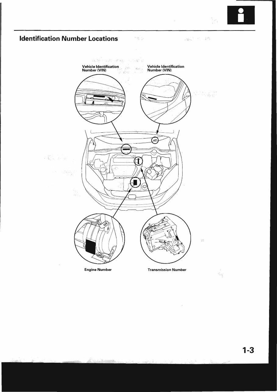
Identification Number Locations
Vehicle Identification Vehicle Identification
Number (VINI Number (VINI
Engine Number Transmission Number
1-3
You're Reading a Preview
What's Included?
Fast Download Speeds
Offline Viewing
Access Contents & Bookmarks
Full Search Facility
Print one or all pages of your manual
$36.99
2007-2011 Honda CR-V Service & Repair Manual
Viewed 27 Times Today

What's Included?
Fast Download Speeds
Offline Viewing
Access Contents & Bookmarks
Full Search Facility
Print one or all pages of your manual
$36.99

Secure transaction
What's Included?
Fast Download Speeds
Offline Viewing
Access Contents & Bookmarks
Full Search Facility
Print one or all pages of your manual
Description
- The 2007-2011 Honda CR-V Service & Repair Manual is a comprehensive resource for fixing vehicle issues, suitable for both professional mechanics and DIY enthusiasts.
- It includes troubleshooting and replacement procedures recommended by the manufacturer, along with step-by-step instructions, clear images, and exploded-view illustrations.
- Regular maintenance is essential for the durability of your vehicle, and this manual provides the necessary guidance for addressing wear and tear over time.
- By following the manufacturer's recommended troubleshooting charts and replacement procedures, you can save on repairs, enhance your vehicle's reliability, and reduce reliance on repair shops.
- The manual offers easy access to specific information without the hassle of flipping through numerous pages, making it more convenient than traditional bound manuals.
- It is available in a printable format and compatible with various electronic devices, including PC, Mac, Android, and Apple devices, with Adobe Reader as the only requirement.


