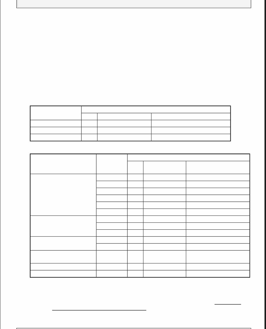
2006-08 SPECIFICATIONS Civic (Except Hybrid) SPECIFICATIONS INDEX CIVIC SPECIFICATIONS INDEX System Specification/Procedure Air Conditioning Service AIR CONDITIONING Torque See applicable component in HEATING/AIR CONDITIONING (EXCEPT HYBRID) article. Axle Nut/Hub Nut Front Except Si 181 N.m (134 ft. lbs.) Si 245 N.m (180 ft. lbs.) Rear 64 N.m (47 ft. lbs.) Battery BATTERY (EXCEPT HYBRID) Brakes Bleeding Sequence BRAKE SYSTEM BLEEDING Disc Brakes BRAKES Drum Brakes BRAKES Torque See applicable component in CONVENTIONAL BRAKE COMPONENTS (EXCEPT HYBRID) article. Charging Generator 1.8L ENGINE ELECTRICAL (R18A1 ENGINE) 2.0L ENGINE ELECTRICAL (K20Z3 ENGINE) Torque 1.8L See applicable figure in ALTERNATOR REMOVAL AND INSTALLATION . 2.0L See applicable figure in ALTERNATOR REMOVAL AND INSTALLATION . Drive Belts Adjustment 1.8L DRIVE BELT INSPECTION 2.0L DRIVE BELT INSPECTION Belt Routing 1.8L DRIVE BELT REMOVAL/INSTALLATION 2.0L DRIVE BELT REMOVAL/INSTALLATION Engine Cooling General Service Specifications 1.8L COOLING SYSTEM (R18A1 ENGINE) 2.0L COOLING SYSTEM (K20Z3 ENGINE) 2006-08 SPECIFICATIONS Civic (Except Hybrid)
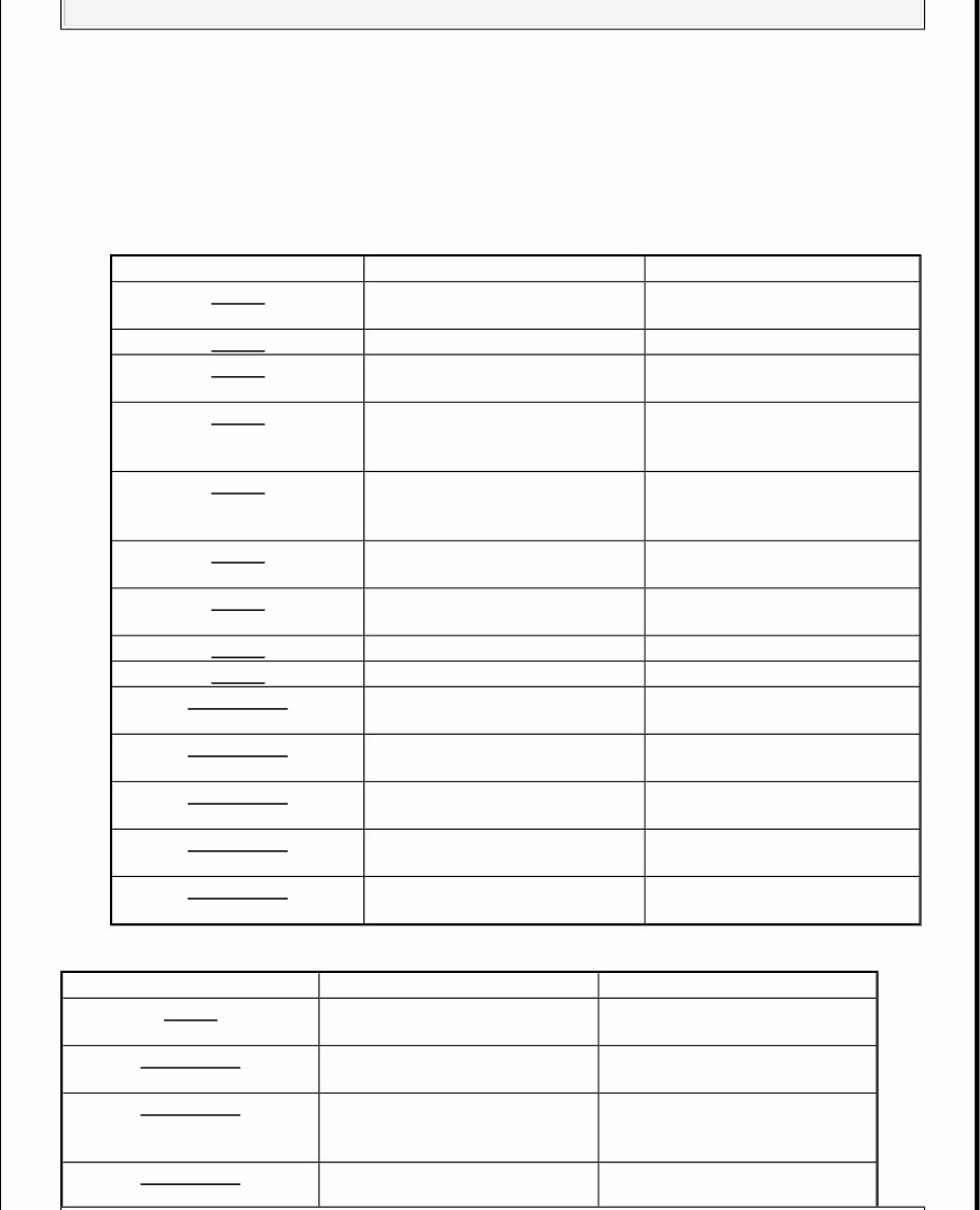
Radiator Cap Pressure 93-123 kPa (0.95-1.25 kgf/cm 2 , 14-18 psi) Thermostat R & I 1.8L THERMOSTAT REPLACEMENT 2.0L THERMOSTAT REPLACEMENT Water Pump R & I 1.8L WATER PUMP REPLACEMENT 2.0L WATER PUMP REPLACEMENT Engine Mechanical Compression 1.8L ENGINE ASSEMBLY (R18A1 ENGINE) 2.0L ENGINE ASSEMBLY (K20Z3 ENGINE) Oil Pressure (176°F (80°C) 1.8L 70 kPa (.7 kgf/cm 2 , 10 psi) @ idle; 340 kPa (3.5 kgf/cm 2 , 50 psi) @ 3000 RPM 2.0L 70 kPa (.7 kgf/cm 2 , 10 psi) @ idle; 300 kPa (3.1 kgf/cm 2 , 44 psi) @ 3000 RPM Overhaul See applicable specifications table in STANDARDS AND SERVICE LIMITS . Torque See applicable component in appropriate ENGINE MECHANICAL article. Fluid Specifications See FLUIDS under MAINTENANCE tab. Flywheel/Flex Plate Torque A/T 74 N.m (54 ft. lbs.) M/T 5-Speed 103 N.m (75 ft. lbs.) 6-Speed 122 N.m (90 ft. lbs.) Fuel System Pressure Specification 1.8L 380-430 kPa (3.9-4.4 kgf/cm 2 , 55-63 psi) 2.0L 330-380 kPa (3.4-3.9 kgf/cm 2 , 48-55 psi) Fuel Pressure Test Procedure 1.8L FUEL PRESSURE TEST 2.0L FUEL PRESSURE TEST Ignition Firing Order & Cylinder Identification 1.8L ENGINE ELECTRICAL (R18A1 ENGINE) 2.0L ENGINE ELECTRICAL (K20Z3 ENGINE) Ignition Wires (Resistance) NA Ignition Wires (Routing) NA Spark Plug Type 2006-08 SPECIFICATIONS Civic (Except Hybrid)
1.8L NGK: IZFR6K-11S; Denso: SKJ20DR-M11S 2.0L NGK: IFR7G-11KS; Denso: SK22PR-M11S Gap 1.0-1.1 mm (.039-.043 in.) Torque 18 N.m (13 ft. lbs.) Starting Starter 1.8L STARTER PERFORMANCE TEST 2.0L STARTER PERFORMANCE TEST Torque 1.8L STARTER REMOVAL AND INSTALLATION 2.0L STARTER REMOVAL AND INSTALLATION Wheel Alignment Adjustment Specifications SUSPENSION Torque Front See applicable component in FRONT SUSPENSION (EXCEPT HYBRID) article. Rear See applicable component in REAR SUSPENSION (EXCEPT HYBRID) article. Wheel & Tire Wheel Lug Nut Torque 108 N.m (80 ft. lbs.) 2006-08 SPECIFICATIONS Civic (Except Hybrid)
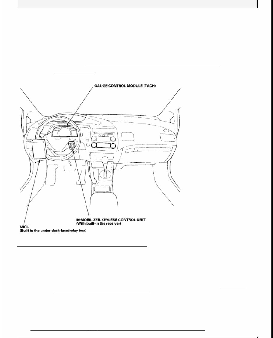
2006-08 ACCESSORIES & EQUIPMENT Multiplex Control System - Civic (Except Hybrid) COMPONENT LOCATION INDEX Fig. 1: Locating Multiplex Control System Components GENERAL TROUBLESHOOTING INFORMATION TROUBLESHOOTING CAN CIRCUIT RELATED PROBLEMS Using the HDS (Preferred method) 1. Go to B-CAN System Diagnosis Test Mode A to check for "Connected units" and DTCs (see TROUBLESHOOTING - B - CAN SYSTEM DIAGNOSIS TEST MODE A ). NOTE: Refer to the MULTIPLEX INTEGRATED CONTROL SYSTEM (GX) (SUPPLEMENT) article for additional information for the GX model. NOTE: Check the ECM/PCM for DTCs and troubleshoot ECM/PCM (see GENERAL TROUBLESHOOTING INFORMATION ) or F-CAN loss of communication errors first. 2006-08 ACCESSORIES & EQUIPMENT Multiplex Control System - Civic (Except Hybrid)
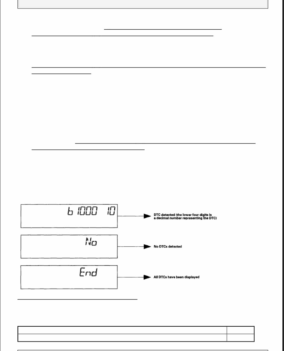
2. If no DTCs are retrieved, go to B - CAN SYSTEM DIAGNOSIS TEST MODE C (see ) or D (see TROUBLESHOOTING - B - CAN SYSTEM DIAGNOSIS TEST MODE D ). Without HDS (Use only if the HDS is unavailable) 1. Check for communication circuit problems using B-CAN System Diagnostic Test (see TROUBLESHOOTING - B - CAN SYSTEM DIAGNOSIS TEST MODE 1 AND TEST MODE 2 (WITHOUT THE HDS) ). 2. Check for DTCs. 3. Sort, and then troubleshoot the DTCs in the order below. 1 Battery voltage DTCs 2 Internal error DTCs 3 Loss of communication DTCs (beginning with the lowest number first; for example, if B1008 and B1011 are retrieved, troubleshoot B1008 first) 4 Signal error DTCs 4. If no DTCs are retrieved, use B-CAN System Diagnostic Test Mode 2 to check all inputs related to failure (see step 10TROUBLESHOOTING - B - CAN SYSTEM DIAGNOSIS TEST MODE 1 AND TEST MODE 2 (WITHOUT THE HDS) ). How to display DTCs on the gauge control module (tach) While in Test Mode 1, the DTCs which have been detected and stored individually by various B-CAN (Body-controller Area Network) units, will be shown one by one on the odometer display when the communication between the MICU and the gauge control module is normal. To scroll through the DTCs, press the select/reset button. Fig. 2: Identifying Gauge Control Module (Tach) The unit that has stored the code can be identified by the number shown on the multi-information display. MICU REFERENCE MICU 10 Gauge control module 50 2006-08 ACCESSORIES & EQUIPMENT Multiplex Control System - Civic (Except Hybrid)
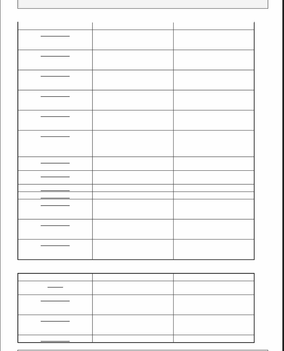
How to clear the DTC While in Test Mode 1, press and hold down the SELECT/RESET button for more than 10 seconds. Loss of Communication DTC cross-reference chart When an ECU is unable to communicate with the other ECUs on the CAN circuit, the other control units will set loss of communication DTCs. Use this chart to find the control unit that is not communicating. 1. Find the Transmitting Control Unit that is in the same row as all of the loss of communication DTCs retrieved. 2. Do the input test for the transmitting control unit. BUS OFF AND INTERNAL ERROR CODES RECEIVING UNIT/LOSS OF COMMUNICATION DTC DTC TROUBLESHOOTING INDEX DTC type Related Unit MICU Gauge Control Module Immobilizer-Keyless Control Unit BUS OFF B1000 B1150 B1900 ECU (CPU) Error B1001 ECU (EEPROM) Error B1002 B1152 Transmitting Control Unit Message Receiving Unit/Loss of Communication DTC MICU Gauge Control Module Immobilizer-Keyless Control Unit MICU RM B1188 HLSW B1155 WIPSW B1156 MICU B1157 DOORSW B1159 DRLOCKSW B1160 B1905 Gauge Control Module VSP/NE B1011 A/T B1008 B1906 CDS (SRS) B1032 ECM/PCM ENG B1168 A/T B1169 ABS or VSA Modulator- Control Unit ABS or VSA B1170 EPS Control Unit EPS B1183 SRS SRS B1187 NOTE: Check the ECM/PCM for DTCs and troubleshoot ECM/PCM (see GENERAL TROUBLESHOOTING INFORMATION ) or F-CAN loss of communication errors first, then record all DTCs, and sort them by DTC type using the DTC troubleshooting index, then troubleshoot the DTC(s) in this order. 2006-08 ACCESSORIES & EQUIPMENT Multiplex Control System - Civic (Except Hybrid)
Battery voltage DTCs Internal error DTCs Loss of communication DTCs (beginning with the lowest number first; for example, if B1008 and B1011 are retrieved, troubleshoot B1008 first). Signal error DTCs MICU REFERENCE GAUGE CONTROL MODULE DTC Description DTC type B1000 Communication bus line error (BUS-OFF) Loss of communication B1001 MICU internal error (CPU error) Internal error B1002 MICU internal error (EEPROM error) Internal error B1008 MICU lost communication with gauge control module (A/T message) Loss of communication B1011 MICU lost communication with gauge control module (VSP/NE message) Loss of communication B1026 Front passenger's door lock switch LOCK/UNLOCK signal error Signal error B1032 MICU lost communication with the SRS unit (CDS message) Signal error B1036 IG1 line input error Signal error B1077 Windshield wiper (As) signal error Signal error DTC B1078 Daytime running lights signal error (Canada) Signal error DTC B1079 Daytime running lights signal error (USA) Signal error DTC B1127 Driver's door key cylinder switch signal error Signal error DTC B1128 Driver's door lock switch signal error Signal error DTC B1129 Driver's door lock knob switch signal error Signal error DTC Description DTC type B1150 Communication bus line error (BUS-OFF) Loss of communication DTC B1152 Gauge control module internal error (EEPROM error) Internal error DTC B1155 Gauge control module lost communication with MICU (Headlight switch message) Loss of communication DTC B1156 Gauge control module lost communication with MICU Loss of communication 2006-08 ACCESSORIES & EQUIPMENT Multiplex Control System - Civic (Except Hybrid)
IMMOBILIZER-KEYLESS CONTROL UNIT (Wiper switch message) DTC B1157 Gauge control module lost communication with MICU (MICU message) Loss of communication DTC B1159 Gauge control module lost communication with MICU (DOORSW message) Loss of communication DTC B1160 Gauge control module lost communication with MICU (DRLOCKSW message) Loss of communication DTC B1168 Gauge control module lost communication with ECM/PCM (Engine messages) Loss of communication DTC B1169 Gauge control module lost communication with PCM (A/T message) Loss of communication DTC B1170 Gauge control module lost communication with ABS modulator-control unit (ABS message) Loss of communication DTC B1175 Fuel level sensor (Fuel gauge sending unit) circuit open Signal error DTC B1176 Fuel level sensor (Fuel gauge sending unit) circuit short Signal error DTC B1177 Battery voltage abnormal Battery voltage DTC B1178 F-CAN communication line error Loss of communication DTC B1183 Gauge control module lost communication with EPS control unit (EPS message) Loss of communication DTC B1187 Gauge control module lost communication with SRS unit (SRS message) Loss of communication DTC B1188 Gauge control module lost communication with MICU (RM message) Loss of communication DTC Description DTC type B1900 Communication bus line error (BUS-OFF) Loss of communication DTC B1905 Immobilizer-keyless control unit lost communication with MICU (DRLOCKSW message) Loss of communication DTC B1906 Immobilizer-keyless control unit lost communication with gauge control module (A/T message) Loss of communication DTC B1925 Ignition key switch signal error Signal error 2006-08 ACCESSORIES & EQUIPMENT Multiplex Control System - Civic (Except Hybrid)
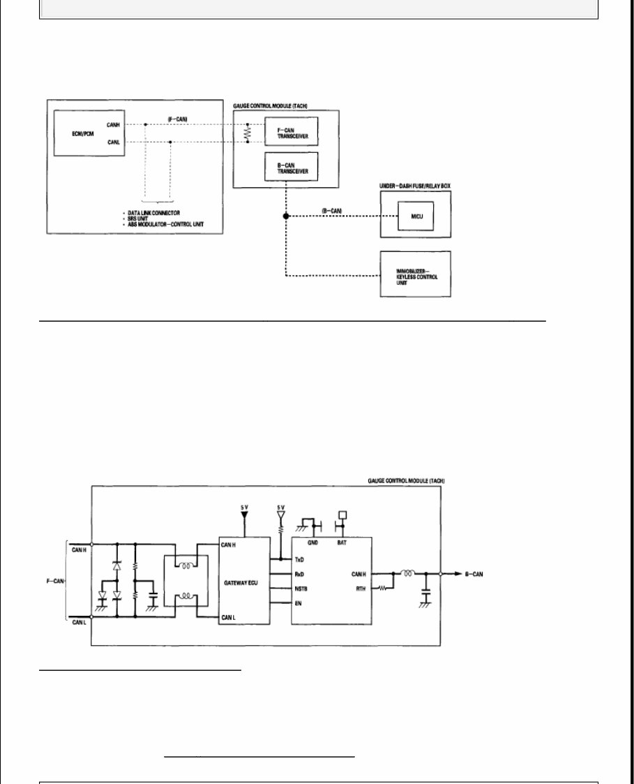
SYSTEM DESCRIPTION MICU CONTROL FUNCTIONS INDEX The MICU (built into the under-dash fuse/relay box) is one of the B-CAN components. The MICU controls many systems related to the body controller area and a security system, and also works as a gateway to diagnose the other B-CAN connected ECUs with the HDS. Refer to each system circuit diagram for details. MICU CONTROL FUNCTIONS The MICU also controls the function of these circuits: Entry lights control (map lights and ceiling light) Exterior lights control (including the daytime running lights control) Horn Interlock system Key-in reminder Keyless entry Lights-on reminder Power door locks Seat belt reminder Security alarm Turn signal/hazard flasher Wiper/washer BODY CONTROLLER AREA NETWORK (B-CAN) AND FAST CONTROLLER AREA NETWORK (F-CAN) The body controller area network (B-CAN) and the fast controller area network (F-CAN) share information between multiple electronic control units (ECUs). B-CAN communication moves at a slower speed (33.33 kbps) for convenience related items and for other functions. F-CAN information moves at a faster speed (500 kbps) for "real time" functions such as fuel and emissions data. To allow both systems to share System Function Multiplex Control Sends the switch input signal information to the MICU and outputs the information. The MICU controls the ECUs electric load and communication based upon the information received the B-CAN. On-Board Diagnosis The MICU has a gateway function which sends the results of the MICU internal diagnosis and the B-CAN connected ECUs diagnosis to the HDS. Self- Diagnosis Test mode 1 diagnoses the communication line between the MICU and B-CAN connected unit. Test mode 2 checks the switch inputs connected to the MICU. Interior Light (s) The MICU controls the interior lights ON, OFF and dimming based upon the information of the related switches and/or the B-CAN related information. Sleep Function The MICU has a sleep function, which it enters during the power down mode. 2006-08 ACCESSORIES & EQUIPMENT Multiplex Control System - Civic (Except Hybrid)
information, the gauge control module translates information from B-CAN to F-CAN and from F-CAN to B-CAN. Fig. 3: Body Controller Area Network (B - CAN) And Fast Controller Area Network (F - CAN) The single wire method is used between the units not requiring the communication to move at a fast speed. Using a single wire method reduces the number of the wires used on the body controller area network. GATEWAY FUNCTION The gauge control module (tach) acts as a gateway to allow both systems to share information, the gauge control module translates information from B-CAN to F-CAN and from F-CAN to B-CAN. Fig. 4: Identifying Gateway Function NETWORK "LOSS OF COMMUNICATION" ERROR CHECKING FUNCTION The ECUs on the CAN circuit send messages to each other. If there are any malfunctions on the network, the odo/trip display on the gauge control module can indicate the error messages by entering the gauge self- diagnostic function (see SELF - DIAGNOSTIC FUNCTION ). 2006-08 ACCESSORIES & EQUIPMENT Multiplex Control System - Civic (Except Hybrid)
The 2007 Honda Civic Service & Repair Manual is your go-to reference for keeping this compact sedan running like it should. Whether you’re working on the 1.8L R18A1 or the 2.0L K20Z3 engine, this manual offers in-depth coverage of essential systems—from engine mechanical procedures to full transmission service.
Expect detailed guidance on front-wheel driveline repairs, brake servicing, HVAC diagnostics, and suspension adjustments. It also includes step-by-step procedures for engine performance tuning, DTC troubleshooting, and component replacement for everything from lighting to restraint systems.
Content overview:
Complete technical specifications and service data
Accessories and equipment repair procedures
Brake system diagnostics, service, and replacement
Driveline and axle service for FWD systems
DTC (Diagnostic Trouble Codes) reference and troubleshooting
Electrical system repair, including wiring and connectors
Engine mechanical service and overhaul procedures
Engine performance diagnostics and tuning procedures
HVAC (heating, ventilation, and air conditioning) service
Lighting system repair and troubleshooting
Maintenance schedule and service procedures
Restraint systems, including seat belts and airbags
Steering system repair and adjustment procedures
Suspension diagnostics and component replacement
Transmission service, rebuild, and adjustment procedures
Built for both experienced mechanics and confident DIYers, this manual lays things out clearly without the fluff. Maintenance intervals, repair procedures, and system specs are all organized for quick reference—ideal for tackling jobs in the garage or out in the shop. Whether you’re chasing down a hard code or doing a weekend rebuild, it’s a solid tool to have on hand.
Printable: Yes Language: English Compatibility: Pretty much any electronic device, incl. PC & Mac computers, Android and Apple smartphones & tablet, etc. Requirements: Adobe Reader (free)