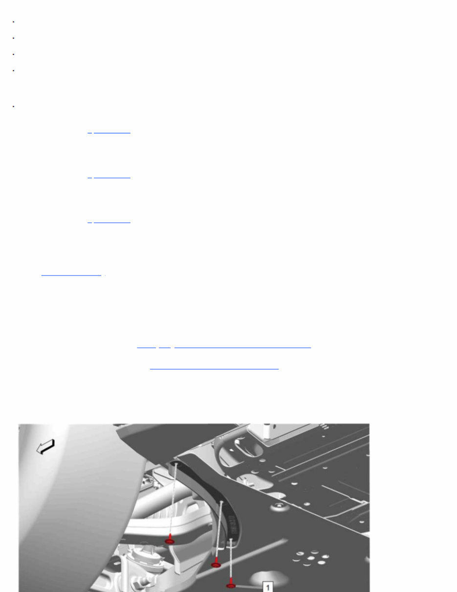
Single Use Fasteners and Components Front Wheel Drive Shaft Nut Front Wheel Drive Shaft Washer Output Shaft Retaining Ring Output Shaft Seal Special Tools Disc Brakes 07CH-42188-B Ball Joint Separator Equivalent regional tools: Special Tools. Front Suspension 07CH-43631 Ball Joint Separator Equivalent regional tools: Special Tools. Wheel Drive Shafts 07-J-45859 Axle Remover Equivalent regional tools: Special Tools. Warning: The battery must be disconnected to prevent the brake master cylinder from pressurizing the hydraulic system during its automated self diagnostic tests that can possibly occur when a door is opened or the key transmitter is activated. Failure to follow this precaution may cause personal injury. Warning: Brake Dust Warning. Removal Procedure Warning: Always ensure the Battery Maintenance Mode is inactive before disconnecting the 12 volt battery. This mode can be active with the ignition off, regardless of whether the vehicle charging cord is plugged in or not. When this mode is active, the on-board high voltage battery charger will energize the 12 volt battery cables and charge the 12 volt battery. Disconnecting the battery cables while this mode is active may result in an electrical shock or a burn from hot battery cable leads. 1. Disconnect the battery negative cable. Battery Negative Cable Disconnection and Connection. 2. Remove the front tire and wheel assembly. Tire and Wheel Removal and Installation. 3. Have an assistant apply the brakes. 4. Front Wheelhouse Liner Bolt - Left Side and Right Side (1) >> Remove [6x]
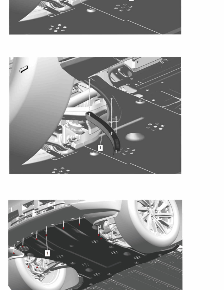
Note: Left side shown, right side similar. 5. Front Tire Front Air Deflector - Left Side and Right Side (1) >> Remove [2x] Note: Left side shown, right side similar. 6. Front Bumper Fascia Bolt (1) >> Remove [10x]
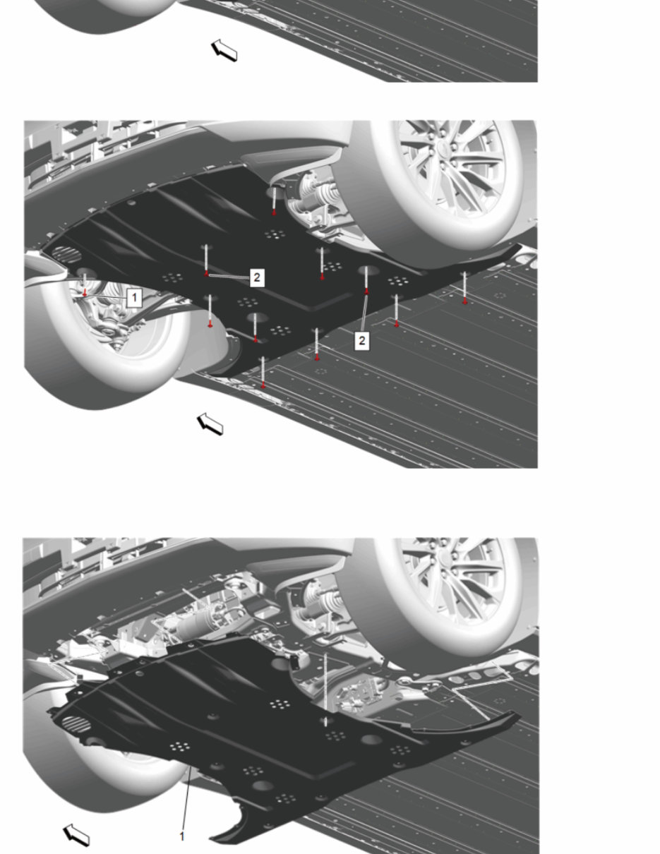
7. Underbody Front Air Deflector Bolt (1) >> Remove [9x] 8. Underbody Front Air Deflector Retainer (2) >> Remove [2x] 9. Front Compartment Insulator (1) >> Remove
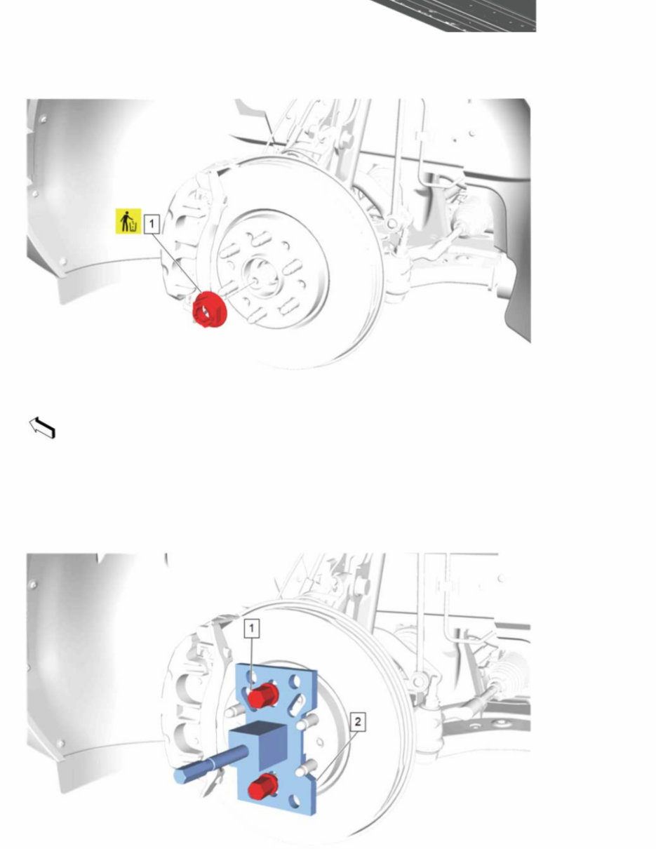
Note: The proper position of the front compartment insulator (1) is above the front bumper lower fascia and the left and right side front wheelhouse liners. 10. Front Wheel Drive Shaft Nut (1) >> Remove and DISCARD Caution: DO NOT use air tools to remove the wheel drive shaft nut. Damage to the wheel drive shaft threads could occur. Use hand tools only. 11. Have an assistant release the brakes. 12. Install the 07-J-45859 Axle Remover (2) to the front wheel hub and secure with 2 wheel nuts (1) hand tightened.
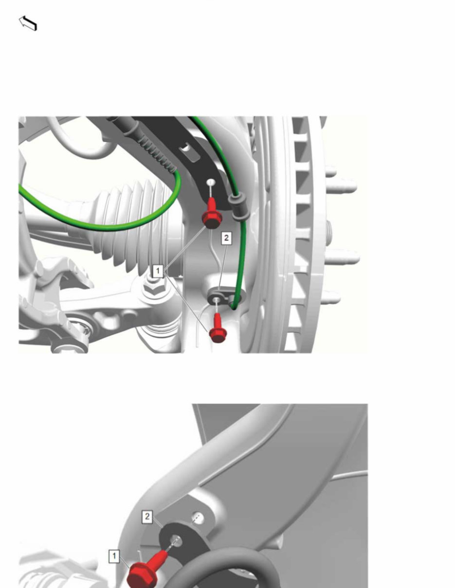
13. Using the 07-J-45859 Axle Remover (2), release the front wheel drive half shaft from the front wheel hub. 14. Remove the 2 wheel nuts (1) and the 07-J-45859 Axle Remover (2) from the front wheel hub. 15. Front Wheel Speed Sensor Bolt (1) >> Remove [2x] 16. Front Wheel Speed Sensor (2) @ Steering Knuckle >> Remove 17. Front Brake Hose Bracket Bolt (1) >> Remove
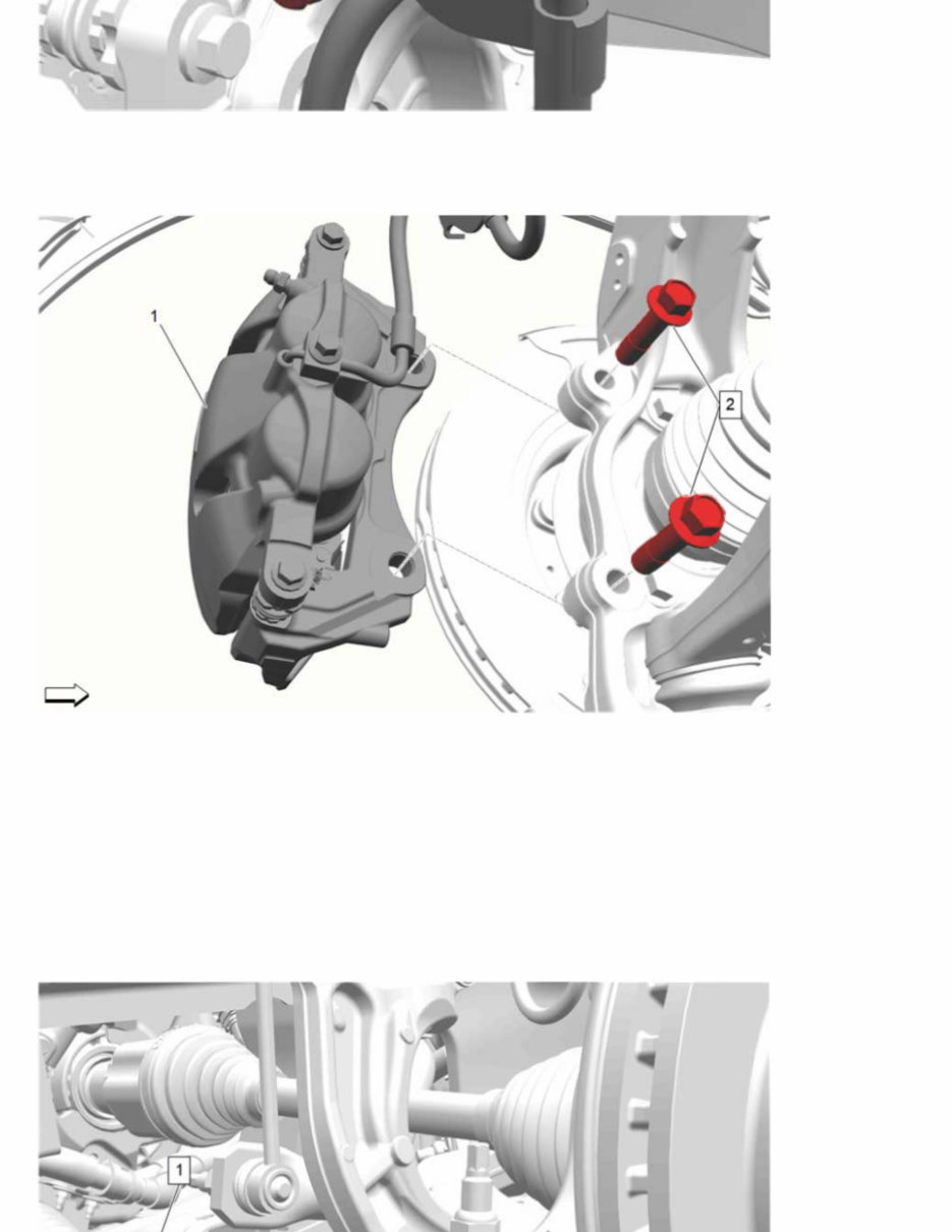
18. Front Brake Hose (2) @ Steering Knuckle >> Reposition 19. Front Brake Caliper Bracket Bolt (2) >> Remove [2x] Caution: Support the brake caliper with heavy mechanic wire, or equivalent, whenever it is separated from its mount and the hydraulic flexible brake hose is still connected. Failure to support the caliper in this manner will cause the flexible brake hose to bear the weight of the caliper, which may cause damage to the brake hose and in turn may cause a brake fluid leak. 20. Remove the front brake caliper and bracket assembly (1) and support with heavy mechanics wire. 21. Using a suitable jack, support the steering knuckle. 22. Place match marks on the steering linkage inner tie rod nut and the steering linkage inner tie rod. 23. Steering Linkage Inner Tie Rod Nut (1) >> Loosen
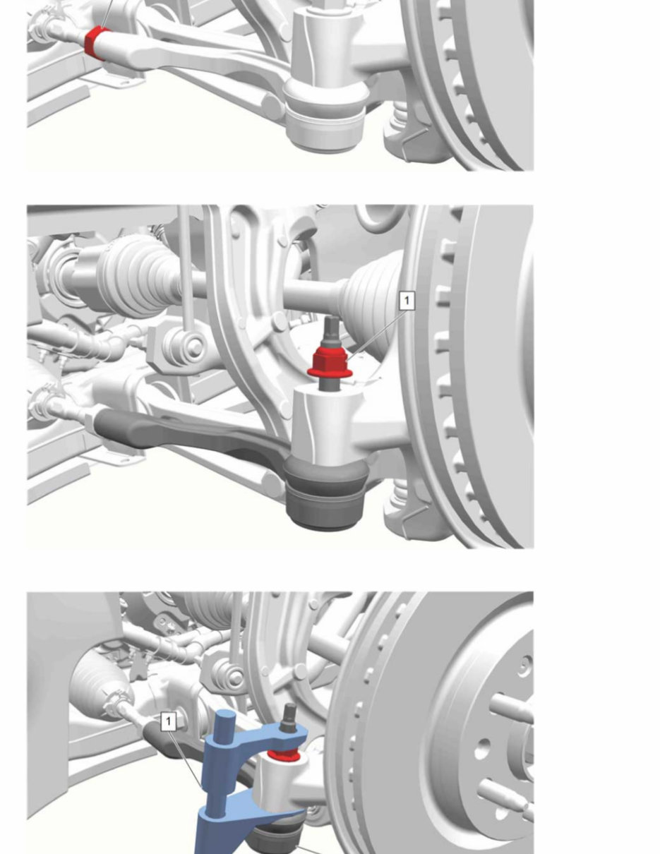
24. Steering Linkage Outer Tie Rod Nut (1) >> Loosen 25. Using 07CH-42188-B Ball Joint Separator (1), separate the steering linkage outer tie rod (2) from the steering knuckle.
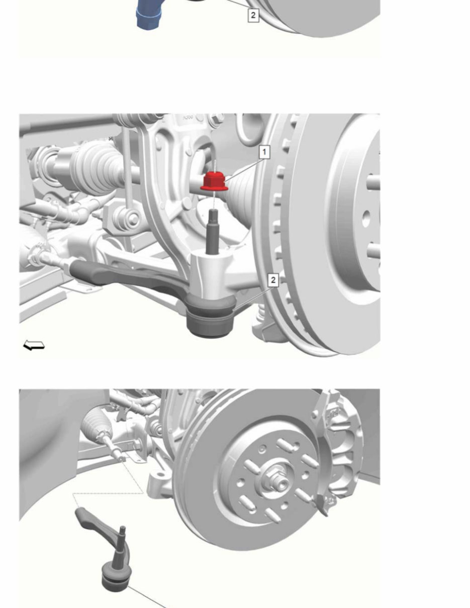
Caution: Do not attempt to disconnect a steering linkage joint by driving a wedge between the joint and the attached part. Seal damage may result which will cause premature failure of the joint. 26. Steering Linkage Outer Tie Rod Nut (1) >> Remove 27. Steering Linkage Outer Tie Rod (1) » Remove
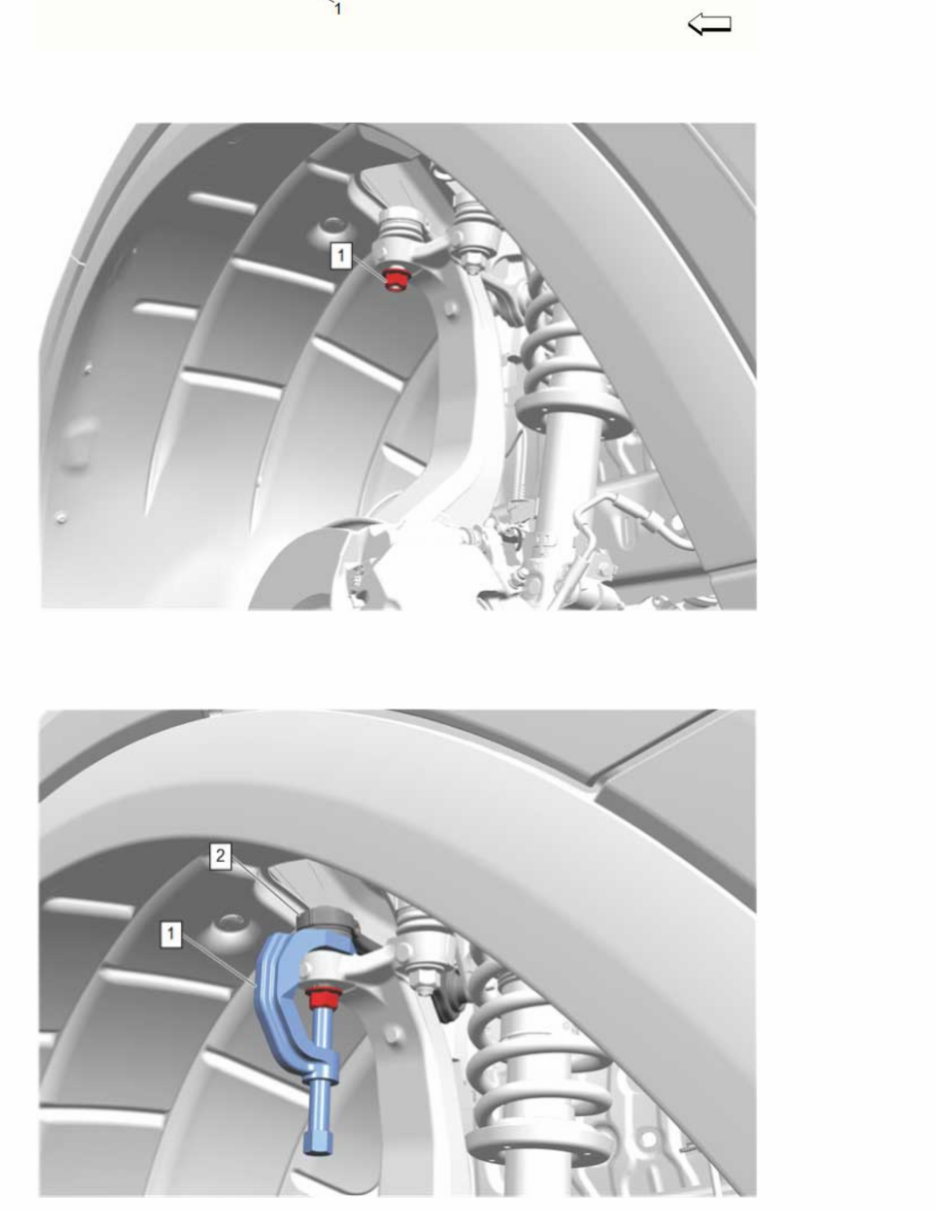
28. Front Upper Control Arm Ball Stud Nut (1) >> Loosen Note: DO NOT allow the ball stud to rotate while loosening the nut. 29. Using the 07CH-43631 Ball Joint Separator (1), separate the front control front link (2) from the steering knuckle.
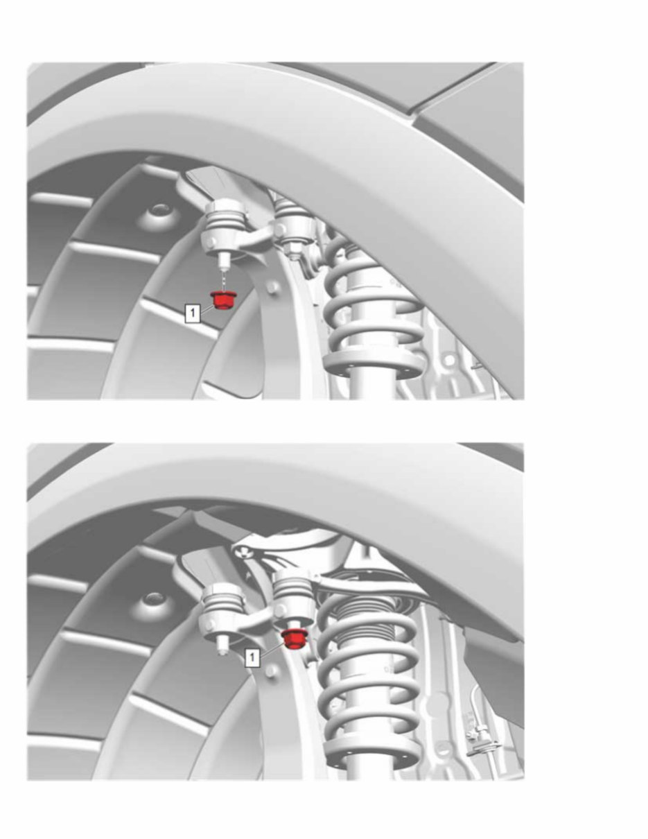
30. Remove the 07CH-43631 Ball Joint Separator (1) from the front control front link (2) and the steering knuckle. 31. Front Upper Control Arm Ball Stud Nut (1) >> Remove 32. Front Upper Control Arm Ball Stud Nut (1) >> Loosen Note: DO NOT allow the ball stud to rotate while loosening the nut. 33. Using the 07CH-43631 Ball Joint Separator (1), separate the front control rear link (2) from the steering knuckle.
Guarantee optimal reliability through detailed expert guidance found in the "2006 Honda Accord Repair Manual," your essential resource for maintaining and repairing your vehicle with confidence. This comprehensive manual offers invaluable insights into critical components like the timing belt replacement and the intricate workings of the braking system, ensuring you tackle repairs with precision and ease. With its organized layout and user-friendly instructions, you’ll benefit from dealership-quality expertise without the hefty price tag, empowering you to perform maintenance tasks that keep your Accord running smoothly. The inclusion of detailed illustrations and troubleshooting tips simplifies even the most complex repairs, making it accessible for both seasoned mechanics and beginners alike. Don’t leave your vehicle’s performance to chance—equip yourself with the knowledge needed to enhance its longevity and reliability.
NOTE: This is a sample. Your actual software manual may differ slightly.
The Repair Manual for the Honda Accord 2006 provides comprehensive information on maintenance, repair, and troubleshooting for the 2006 model of the Honda Accord. This detailed manual is an essential resource for technicians, mechanics, and DIY enthusiasts who aim to keep their vehicle in top condition.
General Information
Introduction
Vehicle Specifications
Identification Numbers
Maintenance
Scheduled Maintenance
Fluid Types and Capacities
Recommended Lubricants
Periodic Inspections
Engine
Engine Mechanical
Engine Electrical
Cooling System
Fuel and Emissions
Exhaust System
Transmission
Automatic Transmission
Manual Transmission
Brakes
Hydraulic System
Mechanical System
Suspension
Front Suspension
Rear Suspension
Steering
Power Steering System
Mechanical Steering
Electrical
Wiring Diagrams
Battery and Charging Systems
Lighting
Audio and Navigation
Body
Exterior
Interior
Heating, Ventilation, and Air Conditioning (HVAC)
Heating System
Cooling System
This manual is designed to provide step-by-step instructions and detailed diagrams to help you perform both routine maintenance and more complex repairs on your Honda Accord 2006. Whether you're a novice or an experienced mechanic, this Repair manual will be an invaluable tool in maintaining the performance and longevity of your vehicle.