ENGINE MECHANICAL (6VE1 3.5L) 6A-1 ENGINE CONTENTS Engine Mechanical ................................................. 6A Engine Cooling........................................................ 6B Engine Fuel ............................................................. 6C Engine Electrical ..................................................... 6D1 Ignition System ....................................................... 6D2 Starting and Changing System............................. 6D3 Driveability and Emissions .....................................6E Engine Exhaust .......................................................6F Engine Lubrication ..................................................6G Engine Speed Control System ..............................6H Induction ...................................................................6J ENGINE MECHANICAL (6VE1 3.5L) CONTENTS Service Precaution ................................................. 6A-2 General Description ............................................... 6A-3 Engine Diagnosis.................................................... 6A-4 Cylinder Head Cover LH........................................ 6A-21 Removal ............................................................... 6A-21 Installation ............................................................ 6A-21 Cylinder Head Cover RH ....................................... 6A-23 Removal ............................................................... 6A-23 Installation ............................................................ 6A-23 Common Chamber................................................. 6A-24 Removal ............................................................... 6A-24 Installation ............................................................ 6A-25 Exhaust Manifold LH.............................................. 6A-26 Removal ............................................................... 6A-26 Installation ............................................................ 6A-26 Exhaust Manifold RH ............................................. 6A-27 Removal ............................................................... 6A-27 Installation ............................................................ 6A-27 Crankshaft Pulley ................................................... 6A-28 Removal ............................................................... 6A-28 Installation ............................................................ 6A-28 Timing Belt .............................................................. 6A-29 Removal ............................................................... 6A-29 Installation ............................................................ 6A-30 Camshaft ................................................................. 6A-34 Removal ............................................................... 6A-34 Installation ............................................................ 6A-34 Cylinder Head ......................................................... 6A-37 Removal ............................................................... 6A-37 Installation ............................................................ 6A-37 Valve Stem Oil Controller , Valve Spring and Valve Guide .................................................... 6A-39 Removal ................................................................ 6A-39 Installation............................................................. 6A-39 Piston, Piston Ring and Connecting Rod ............ 6A-40 Removal ................................................................ 6A-40 Installation............................................................. 6A-41 Crankshaft and Main Bearings.............................. 6A-43 Removal ................................................................ 6A-43 Installation............................................................. 6A-44 Rear Oil Seal ........................................................... 6A-48 Removal ................................................................ 6A-48 Installation............................................................. 6A-48 Engine Assembly .................................................... 6A-49 Removal ................................................................ 6A-49 Installation............................................................. 6A-49 Cylinder Head .......................................................... 6A-52 Cylinder Head and Associated Parts ................ 6A-52 Disassembly ......................................................... 6A-53 Clean ..................................................................... 6A-53 Inspection and Repair ......................................... 6A-53 Reassembly.......................................................... 6A-54 Valve Spring, Oil Controller, Valve, Valve Guide ....................................................................... 6A-56 Valve Spring, Oil Controller, Valve, Valve Guide and Associated Parts ............................. 6A-56 Disassembly ......................................................... 6A-57 Inspection and Repair ......................................... 6A-57 Reassembly.......................................................... 6A-61 Camshaft .................................................................. 6A-64 Camshaft and Associated Parts ........................ 6A-64 Disassembly ......................................................... 6A-64 Inspection and Repair ......................................... 6A-65 Reassembly.......................................................... 6A-67
6A-2 ENGINE MECHANICAL (6VE1 3.5L) Crankshaft ............................................................... 6A-71 Crankshaft and Associated Parts ..................... 6A-71 Disassembly ........................................................ 6A-71 Inspection and Repair ........................................ 6A-73 Reassembly ......................................................... 6A-75 Piston and Connecting Rod .................................. 6A-79 Piston, Connecting Rod and Associate Parts .................................................................... 6A-79 Disassembly ........................................................ 6A-79 Inspection and Repair ........................................ 6A-80 Reassembly ......................................................... 6A-84 Cylinder Block ......................................................... 6A-87 Cylinder Block and Associated Parts ............... 6A-87 Disassembly ........................................................ 6A-88 Inspection and Repair ........................................ 6A-88 Reassembly ......................................................... 6A-89 Main Data and Specification ................................. 6A-93 Special Tool ......................................................... 6A-99 Service Precaution WARNING: THIS VEHICLE HAS A SUPPLEMENTAL RESTRAINT SYSTEM (SRS). REFER TO THE SRS COMPONENT AND WIRING LOCATION VIEW IN ORDER TO DETERMINE WHETHER YOU ARE PERFORMING SERVICE ON OR NEAR THE SRS COMPONENTS OR THE SRS WIRING. WHEN YOU ARE PERFORMING SERVICE ON OR NEAR THE SRS COMPONENTS OR THE SRS WIRING, REFER TO THE SRS SERVICE INFORMATION. FAILURE TO FOLLOW WARNINGS COULD RESULT IN POSSIBLE AIR BAG DEPLOYMENT, PERSONAL INJURY, OR OTHERWISE UNNEEDED SRS SYSTEM REPAIRS. CAUTION: Always use the correct fastener in the proper location. When you replace a fastener, use ONLY the exact part number for that application. ISUZU will call out those fasteners that require a replacement after removal. ISUZU will also call out the fasteners that require thread lockers or thread sealant. UNLESS OTHERWISE SPECIFIED, do not use supplemental coatings (Paints, greases, or other corrosion inhibitors) on threaded fasteners or fastener joint interfaces. Generally, such coatings adversely affect the fastener torque and the joint clamping force, and may damage the fastener. When you install fasteners, use the correct tightening sequence and specifications. Following these instructions can help you avoid damage to parts and systems.
ENGINE MECHANICAL (6VE1 3.5L) 6A-3 General Description Engine Cleanliness And Care An automobile engine is a combination of many machined, honed, polished and lapped surfaces with tolerances that are measured in the thousandths of a millimeter (ten thousandths of an inch). Accordingly, when any internal engine parts are serviced, care and cleanliness are important. Throughout this section, it should be understood that proper cleaning and protection of machined surfaces and friction areas is part of the repair procedure. This is considered standard shop practice even if not specifically stated. · A liberal coating of engine oil should be applied to all friction areas during assembly to protect and lubricate the surfaces on initial operation. · Whenever valve train components, pistons, piston rings, connecting rods, rod bearings, and crankshaft journal bearings are removed for service, they should be retained in order. · At the time of installation, they should be installed in the same locations and with the same mating surfaces as when removed. · Battery cables should be disconnected before any major work is performed on the engine. Failure to disconnect cables may result in damage to wire harness or other electrical parts. · The six cylinders of this engine are identified by numbers; Right side cylinders 1, 3 and 5, Left side cylinders 2, 4 and 6, as counted from crankshaft pulley side to flywheel side. General Information on Engine Service The following information on engine service should be noted carefully, as it is important in preventing damage and contributing to reliable engine performance. · When raising or supporting the engine for any reason, do not use a jack under the oil pan. Due to the small clearance between the oil pan and the oil pump strainer, jacking against the oil pan may cause damage to the oil pick-up unit. · The 12-volt electrical system is capable of damaging circuits. When performing any work where electrical terminals could possibly be grounded, the ground cable of the battery should be disconnected at the battery. · Any time the intake air duct or air cleaner is removed, the intake opening should be covered. This will protect against accidental entrance of foreign material into the cylinder which could cause extensive damage when the engine is started. Cylinder Block The cylinder block is made of aluminum die-cast casting for 75°V-type six cylinders. It has a rear plate integrated structure and employs a deep skirt. The cylinder liner is cast and the liner inner diameter and crankshaft journal diameter are classified into grades. The crankshaft is supported by four bearings of which width is different between No.2, No.3 and No.1, No.4; the width of No.3 bearing on the body side is different in order to support the thrust bearing. The bearing cap is made of nodular cast iron and each bearing cap uses four bolts and two side bolts. Cylinder Head The cylinder head, made of aluminum alloy casting employs a pent-roof type combustion chamber with a spark plug in the center. The intake and exhaust valves are placed in V-type design. The ports are cross-flow type. Valve Train Intake and exhaust camshaft on the both side of banks are driven through an camshaft drive gear by timing belt. The valves are operated by the camshaft and the valve clearance is adjusted to select suitable thickness shim. Intake Manifold The intake manifold system is composed of the aluminum cast common chamber and intake manifold attached with six fuel injectors. Exhaust Manifold The exhaust manifold is made of nodular cast iron. Pistons and Connecting Rods Aluminum pistons are used after selecting the grade that meets the cylinder bore diameter. Each piston has two compression rings and one oil ring. The piston pin made of chromium steel is offset 1mm toward the thrust side, and the thrust pressure of piston to the cylinder wall varies gradually as the piston travels. The connecting rods are made of forged steel. The connecting rod bearings are graded for correct size selection. Crankshaft and Bearings The crankshaft is made of Ductile cast-iron. Pins and journals are graded for correct size selection for their bearing. Engine Control Module (ECM) The ECM location is on the common charmber.
You're Reading a Preview
What's Included?
Lifetime Access
Fast Download Speeds
Offline Viewing
Access Contents & Bookmarks
Full Search Facility
Print one or all pages of your manual
$31.99
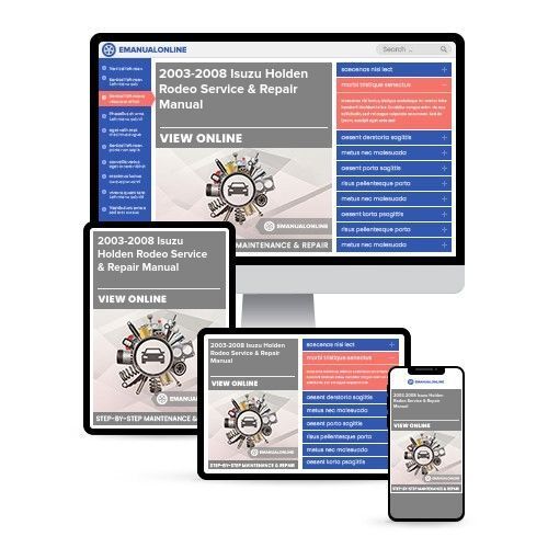
2003-2008 Isuzu Holden Rodeo Service & Repair Manual
The ISUZU HOLDEN RODEO 2003-2008 Full Service Repair Manual is the ultimate guide for anyone looking to maintain, repair, or service their vehicle. This comprehensive manual covers all models released between 2003 and 2008, providing detailed instructions and diagrams to help you navigate through any repair or maintenance procedure.
Whether you are a professional mechanic or a DIY enthusiast, this manual will be your go-to resource. It includes step-by-step instructions, accompanied by clear and concise diagrams, making it easy to understand and follow along. From basic maintenance tasks like oil changes and tire rotations to more complex procedures like engine overhauls and transmission repairs, this manual has got you covered.
With this Full Service Repair Manual, you can save time and money by performing repairs and maintenance on your own. Say goodbye to expensive trips to the dealership or repair shop, and hello to the satisfaction of fixing your vehicle yourself. Not only will you gain valuable knowledge and skills, but you will also have the confidence to tackle any issue that arises with your ISUZU HOLDEN RODEO.
Investing in this manual is a smart choice for any ISUZU HOLDEN RODEO owner. Don't let a mechanical issue or maintenance task intimidate you. With the ISUZU HOLDEN RODEO 2003-2008 Full Service Repair Manual, you will have the guidance and expertise you need to keep your vehicle running smoothly for years to come.
ISUZU HOLDEN RODEO 2003
ISUZU HOLDEN RODEO 2004
ISUZU HOLDEN RODEO 2005
ISUZU HOLDEN RODEO 2006
ISUZU HOLDEN RODEO 2007
ISUZU HOLDEN RODEO 2008
Reviews
Q&A
Recently Viewed
5,521,897Happy Clients
2,594,462eManuals
1,120,453Trusted Sellers
15Years in Business
Price:
Actual Price:
2003-2008 Isuzu Holden Rodeo Service & Repair Manual







 Lifetime Access




