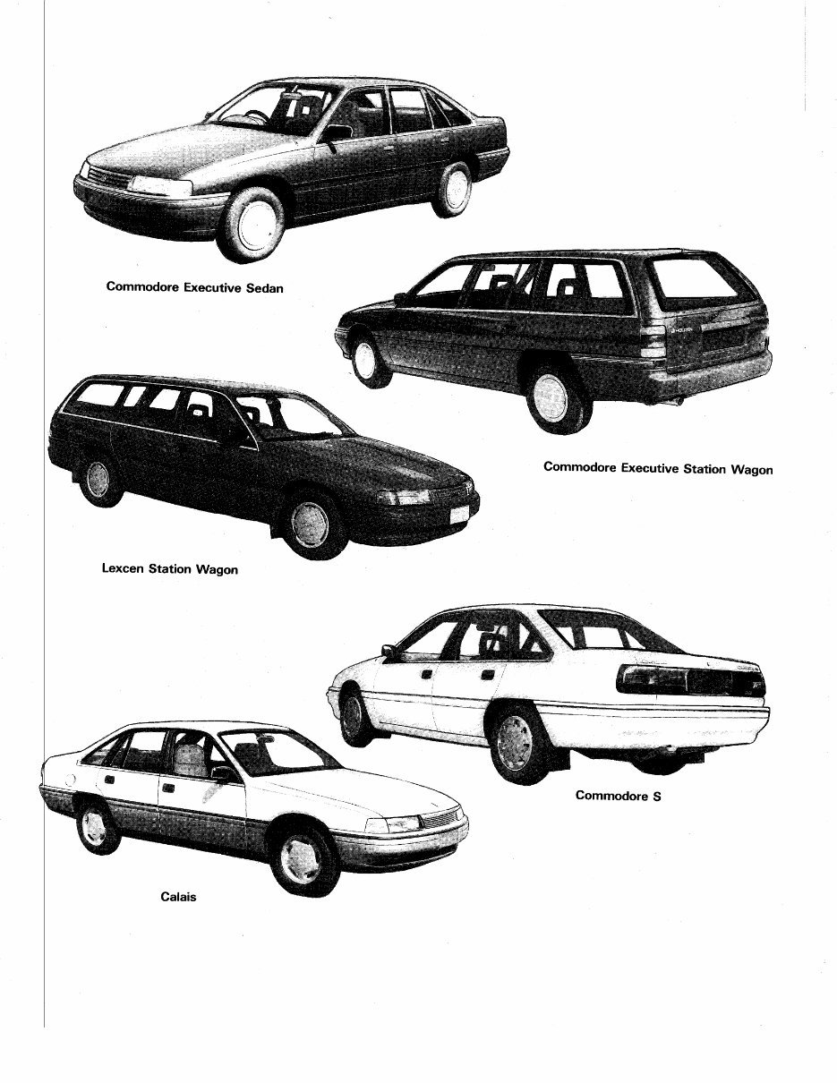
!:r : : i:rr.: Lexcen Station Wagon Commodore Executive Station Wagon Commodore S Not for distribution outside of AllCarManuals.com
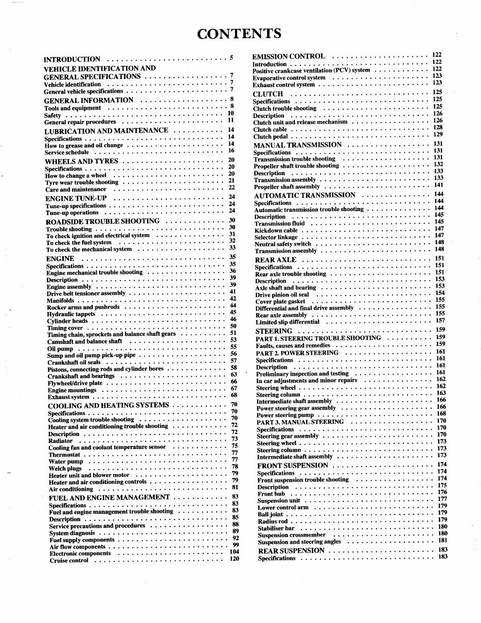
CONTENTS INTRODUCTION VEHICLE IDENTIFICATION AND GENERALSPECIFICATIONS . . . Vehicle identification General vehicle specifications . . GENERAL INFORMATION Tools and equipment Safety General repair procedures LUBRICATION AND MAINTENANCE Specifications . . . How to grease and oil change Service schedule WHEELS AND TYRES Specifications .... How to change a wheel Tyre wear trouble shooting Care and maintenance . . ENGINE TUNE-T'P Tune-up specifications . . Tune-upoperations ROADSIDE TROUBLE SHOOTING Trouble shooting To check ignition and electrical system To check the fuel sYstem To check the mechanical sYstem ENGINE Specifications . . Engine mechanical trouble shooting Description Engine assembly Drive belt tensioner assemblY Manifolds Rocker arms and Pushrods EMISSION CONTROL Introduction . . . Positive crankcase ventilation (PCV) system Evaporative control sYstem Exhaustcontrol sYstem CLUTCH Specifications Clutch trouble shooting Description Clutch unit and release mechanism 122 122 7 7 7 E 8 10 11 14 14 t4 t6 20 20 20 2l 22 24 u u 30 30 3l 32 33 35 35 36 39 39 4l 42 4 45 6 50 51 53 56 57 58 63 6 (I 68 70 70 70 72 72 73 75 77 77 7E 79 79 81 83 83 83 E5 88 E9 92 99 104 t?.o 1?2 r23 L23 125 125 r25 126 126 128 129 131 131 l4 145 145 147 t4it 14E 148 151 151 151 153 153 balance shaft gears ptpe . Clutch cable Clutch pedal MANUAL TRANSMISSION Specifications Transmission trouble shooting Propeller shaft trouble shooting Description Transmissionassembly .--.:.t.:.. Propeller shaft assemblY . . AUTOMATIC TRANSMISSION Specifications DPglllr!4nvut Automatic transmission troubl trouble shooting Description Transmission fluid Kickdowncable . . . Selector linkage Neutral safety switch Transmission assemblY REAR AXLE Specifications . . . Rear axle trouble shooting Description Axle shaft and bearing Drive pinion oil seal Cover plate gasket Differential and Frnal drive assembly Rear axle assembly Limited slip differential STEERING PART 1. STEERING TROUBLE SHOOTING Faults,causes and remedies PART 2. POWER STEERING Specifications ..... Description Preliminary inspection and testing minor repairs In car adjustments and Steering wheel Steering column Intermediate shaft assemblY Power steering gear assemblY Power steering PumP PART 3. MANUAL STEERING Specifrcations Steering gear assembly . . . Steering wheel Steering column Intermediate shaft assemblY FRONT SUSPENSION . Specifications Fiont suspension trouble shooting Description Fronthub .r.. Suspension unit Lower control arm Ball joint Radius rod . . Stabiliser bar Suspension crossmember Suspension and steering angles REAR SUSPENSION. Specifications 131 132 133 133 t{r 14 t4 Hydraulic tappets Cvlinder heads r54 155 155 155 157 159 159 159 161 t6l. Timing cover . Timing chain, sprockets and Camshaft and balance shaft Oil pump Sump and oil pump Pick-uP Crankshaft oil seals Pistons, connecting rods and cylinder bores . Crankshaft and bearings FlywheeUdrive plate Enginemountings . . . ! Exhaust system COOLING AND HEATING SYSTEMS Specifications . . . Cooling system trouble shooting Heater and air conditioning trouble shooting Description Radiator Cooting fan and coolant temperature sensor Thermostat . . . Water pump Welch plugs Ileater unit and blower motor Heater and air conditioning controls Air conditioning FUEL AND ENGINE MANAGEMENT Specifications . . . Fuel and engine management trouble shooting Description Service precautions and procedures System diagnosis Fuel supply comPonents Air flow components Electronic components Cruise control 161 161 162 162 163 16 t6 168 170 t70 170 173 r73 r73 t74 r74 174 175 176 177 179 179 179 1E0 180 181 183 183 Not for distribution outside of AllCarManuals.com
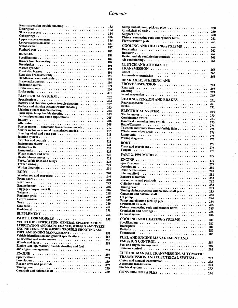
Contents Rear suspension Description . . . Shock absorbers trouble shooting Sump and oil pump pick-up pipe . Crankshaft oil seals Support brace . Pistons,connectingrods and cylin6sr bores . Flywheel/Drive plate COOLING AI\D IIEATING SYSTEMS Description Radiator Heater and air conditioning controls Air conditioning. . CLUTCII AND AUTOMATIC TRANSMISSION Clutch Automatic transmission REAR AXLE, STEERING AND FRONT SUSPENSION . Rear axle IteerinS Front suspension REAR SUSPENSION AND BRAKES Rearsuspension. .. Brakes ELECTRICAL SYSTEM Starter motor Combinationswitch : : :: ::: : : :: :''' llandbrakewarninglampswitch . : : : : ::.::. : :: Radio/Cassette To checkand renewfuses and fusible links. Windscreen wiper arms . . . . Lamp units Wiring diagrams BODY. Front and rear doors . Tailgate PART z.I99IMODELS ENGINE.!.. Specifications . . Description Drive belt tensioner Inletmanifold. . . Exhaust manifolds Rocker arms and pushrods Cylinder heads Timing cover Tfuning qh.io, sprocketsand balanceshaft gears Camshaft and balanceshaft . Oil pump Sump and oil pump pick-up pipe . Crankshaft oil seals Pistons,connectingrods and cylinder hores . Crankshaftand bearings. . . Exhaust system COOLING AND HEATING SYSTEMS Specifications . . Description !.,. Radiator .... Thermostat FUEL AND ENGIIYE MANAGEMENT AND EMISSION CONTROL Fuel and enginemanagement . . . Emission control CLUTCH, MANUAL TRANSMISSION, AUTOMATIC TRANSMISSIONANDELECTRICAL SYSTEM. . . . . Clutch and manual transmlssion Automatictransmission . r . . Electrical system COIYVERSION TABLES 2ffi 260 2ffi 26r 261 262 262 262 263 2& 265 x5 26s 269 269 269 269 271 271 271 273 273 273 273 n4 276 n6 276 2n 27E 278 278 183 184 184 186 185 187 187 188 189 r89 1E9 r9l l9L 194 t96 198 r99 199 200 201 ?.02 202 202 203 204 205 205 ?.M 208 212 2ts 2r8 218 218 221 ?22 223 ?26 228 228 229 23r 240 Coil springs . . Upper suspension arms Lower suspension arms Stabiliser bar Panhard rod BRAKES Specifications Brakes trouble shooting Description Master cylinder Front disc brakes Rear disc brake assembly Handbrake lever and cable . B,rakeadjustments Hydraulic system Brake servo unit Brakepedal . ,.. ELECTRICAL SYSTEM . Specifications. . . -. . . :: : : : : : : : : : : : : : : : : : : : : lattery and charging systemtrouble shooting I*!"ry aud starting systemtrouble shooting Lighting systemtrotble shooting Turn signal lamp trouble shooting Test equipment and someapplicahons B{tery Alternator Starter motor - automatic transmissionmodels Starter motor - manual transmission models !t"."itrg wheel and horn pad . Ignition system Switchesand controls . . . rnstrument cluster Radior/cassette lqnp unlts . Wiper motors and arms Heater blower motor Fuses, fusible links and relays Trailer wiring Wiring diagra+s BODY Windscreen and rear glass Front doors . U0 Rear doors Engine bonnet ZM Luggage compartment lid . . Tailgate 248 Radiator grille . Centre console Seats !... Seat belts ?.Sl Dashboard ST]PPLEMENT . 254 PART 1. l99OMODELS 279 219 279 ?aa 281 ?,81 282 282 282 283 283 2M & 2U 285 2E5 28s 286 VEHICLE IDENTIFICATION, GENBRAL SPECIFICATIONS, LUBRICATION AND MAINTENANCE, WHEELS AND TYRES, ENG_INE TUNE.TTP, ROADSIDE TROUBLB SHOOTING AND FUEL AIID ENGINE MANAGEMENT. . Vehicle identification and generalspecifrcations Lubrication and maintenance Wheelsand tyres Engine tune-up, roadsidetrouble shmting and fuel and enginemsnagement . . . ?37 2yr NI 2gl 2E8 2E9 2E9 ?.92 293 293 293 293 294 2s5 2s5 25s 255 255 259 2s9 259 259 2s9 2@ ENGINE Specifications pecription Iocker arms and pushrods Timingcover. i . .. Camshaft and balance shaft Not for distribution outside of AllCarManuals.com
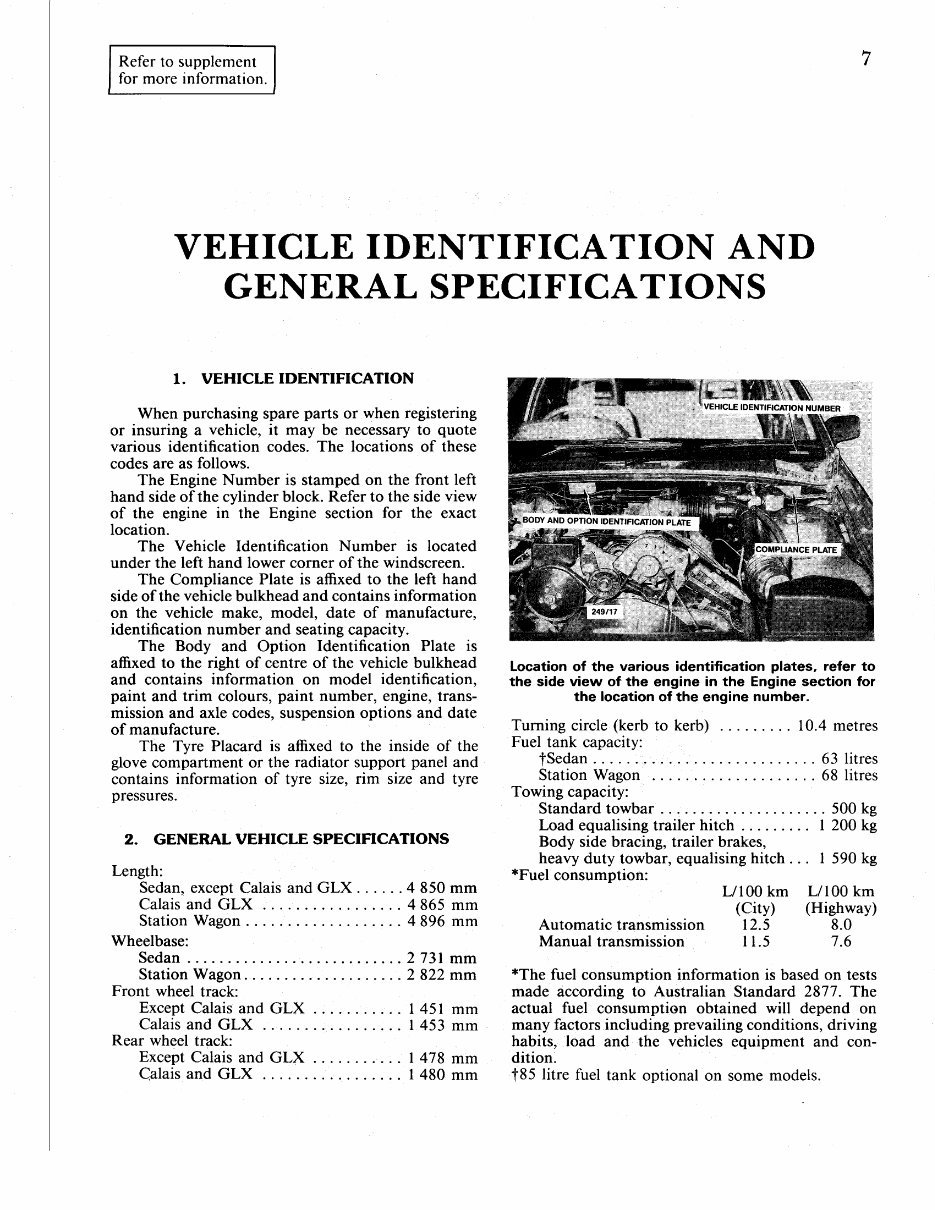
Referto supplement for more information. I VEHICLE IDENTIFICATION AND GENERAL SPECIFICATIONS 1. VEHICLE IDENTIFICATION When purchasingspareparts or when registering or insuring a vehicle, it may be necessary to quote various identification codes. The locations of these codesare as follows. The Engine Number is stamped on the front left hand side of the cylinder block. Refer to the side view of the engine in the Engine section for the exact location. The Vehicle Identification Number is located under the left hand lower corner of the windscreen. The Compliance Plate is affixed to the left hand side of the vehicle bulkhead and contains information on the vehicle make, model, date of manufacture, identification number and seatingcapacity. The Body and Option Identification Plate is affixed to the right of centre of the vehicle bulkhead and contains information on model identification. paint and trim colours, paint number, engine, trans- mission and axle codes, suspension options and date of manufacture. The Tyre Placard is affixed to the inside of the glove compartment or the radiator support panel and contains information of tyre size, rim size and tyre pressures. 2. GENERAL VEHICLE SPECIFICATIONS Length: Sedan, exceptCalais and GLX . 4 850 mm Calais and GLX . . 4 865 mm Station Wagon . ... 4 896 mm Wheelbase: Sedan ..2731 mm Station Wagon 2 822 mm Front wheel track: Except Calais and GLX Calais and GLX . . I 453 mm Rear wheel track: Except Calais and GLX . I 478 mm Calais and GLX . . I 480 mm Location of the various identification plates, refer to the side view of the engine in the Engine section for the location of the enginenumber. Turning circle (kerb to kerb) . . . . 10.4 metres Fuel tank capacity: fSedan .! ... .. 63 litres Station Wagon 68 litres Towing capacity: Standard towbar . 500 kg Load equalisingtrailer hitch I 200 kg Body side bracing, trailer brakes, heavy duty towbar, equalising hitch. . . I 590 kg *Fuel consumption: L/l 00 km L/ 100 km (City) (Highway) Automatic transmission 12.5 8.0 Manual transmission I 1.5 7.6 *The fuel consumption information is based on tests made according to Australian Standard 2877. The actual fuel consumption obtained will depend on many factors including prevailing conditions, driving habits, load and the vehicles equipment and con- dition. t85 litre fuel tank optional on some models. Not for distribution outside of AllCarManuals.com
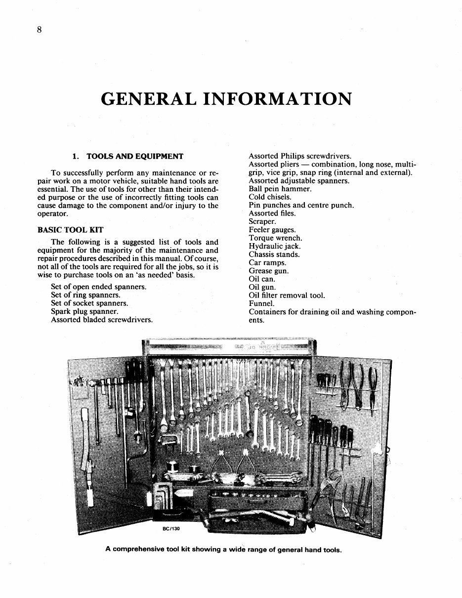
GENERAL INFORMATION 1. TOOLS AhrD EQUIPMENT To successfully perform any maintenance or re- pair work on a motor vehicle, suitable hand tools are essential. The use of tools for other than their intend- ed purpose or the use of incorrectly fitting tools can cause damageto the component and/or injury to the operator. BASIC TOOL KIT The following is a suggested list of tools and equipment for the majority of the maintenance and repair procedures described in this manual. Of course, not all of the tools are required for all the jobs, so it is wise to purchase tools on an'as needed'basis. Set ofoBen ended spanners. Set of ring spanners. Set of socket spanners. Spark plug spanner. Assortedbladed screwdrivers. Assorted Philips screwdrivers. Assortedpliers combination, long nose,multi- grip, vice grip, snap ring (internal and external). Assorted adjustablespanners. Ball pein hammer. Cold chisels. Pin punchesand centre punch. Assorted files. Scraper. Feelergauges. Torque wrench. Hydraulic jack. Chassis stands. Car ramps. Grease gun. Oil can. Oil gun. Oil filter removal tool. Funnel. Containersfor draining oil and washingcompon- ents. A comprehensive tool kit showing a wide range of general hand tools. Not for distribution outside of AllCarManuals.com
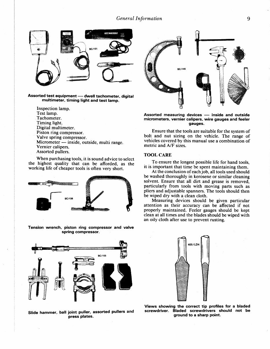
Slide hammer, ball ioint puller' assorted press Plates. General Information Assortedtest equipment - dwell tachometer, digital multimeter,timing light and test lamp. Inspectionlamp. Test lamp. Tachometer. Timing light. Digital multimeter. Piston ring compressor. Valve spring compressor. Micrometer - inside, outside, multi range. Vernier calipers. Assortedpullers. When purchasing tools, it is sound advice to select the highest quality that can be afforded, as the working life of cheaper tools is often very short. Tension wrench, piston ring compressor and valve spnng compressor. Assorted measuring devices - inside and outside micrometers, verniercalipers, wire gaugesand feeler gauges. Ensure that the tools are suitablefor the systemof bolt and nut sizing on the vehicle. The range of vehicles coveredby this manual use a combination of metric and A/F sizes. TOOL CARE To ensurethe longestpossiblelife for hand tools, it is important that time be spent maintaining them. At the conclusionof each job, all tools usedshould be washedthoroughly in kerosene or similar cleaning solvent. Ensure that all dirt and grease is removed, particularly from tools with moving parts such as pliers and adjustablespanners. The tools should then be wiped dry with a clean cloth. Measuring devices should be given particular attention as their accuracy can be affected if not properly maintained. Feeler gauges should be kept cleanat all times and the bladesshould be wiped with an oily cloth after use to prevent rusting. Views showing the correct tip profiles for a bladed screwdriver. Bladed screwdrivers should not be ground to a sharp point. ,-t-e T_' ffiffi tt I pullers and Not for distribution outside of AllCarManuals.com
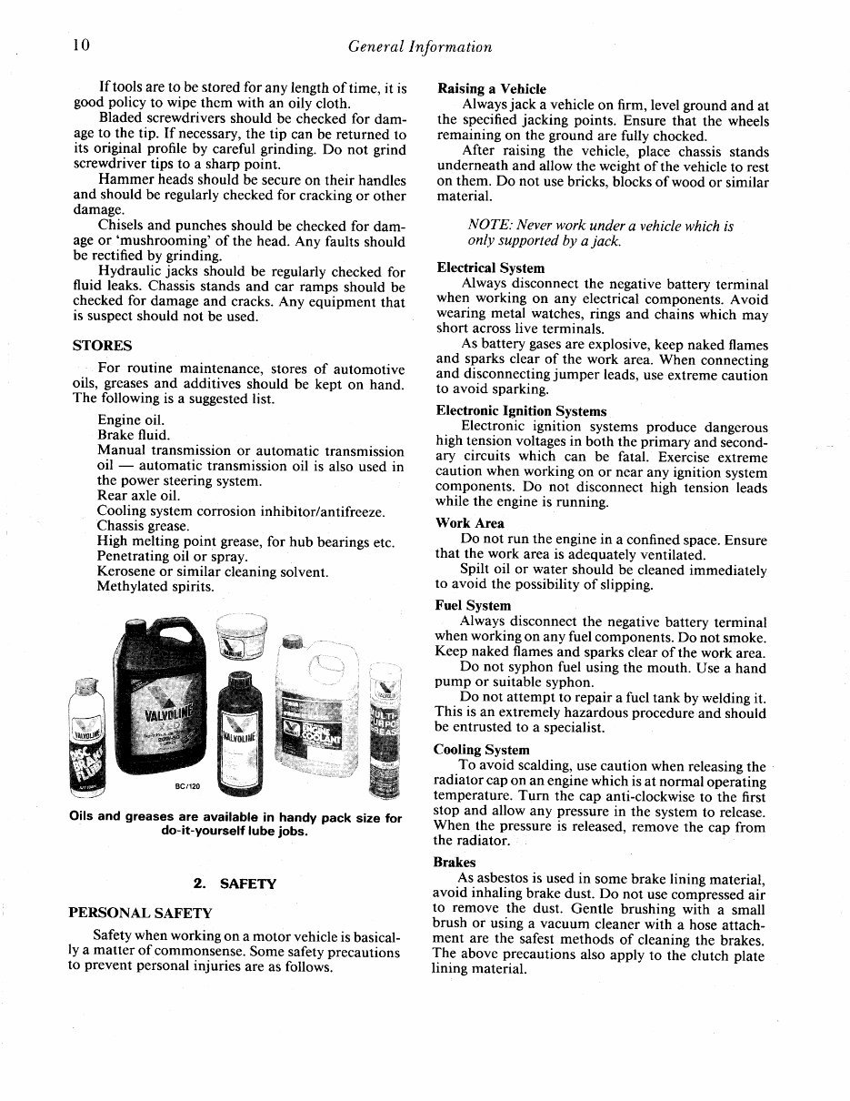
10 General Information If tools are to be stored for any length of time, it is good policy to wipe them with an oily cloth. Bladed screwdriversshould be checkedfor dam- ageto the tip. If necessary, the tip can be returned to its original profile by careful grinding. Do not grind screwdrivertips to a sharp point. Hammer headsshould be secure on their handles and shoutd be regularly checked for cracking or other damage. Chisels and punches should be checkedfor dam- age or 'mushrooming' of the head. Any faults should be rectified by grinding. Hydraulic jacks should be regularly checked for fluid leaks. Chassisstands and car ramps should be checkedfor damageand cracks.Any equipment that is suspect should not be used. STORES For routine maintenance, stores of automotive oils, greases and additives should be kept on hand. The following is a suggested list. Engineoil. Brake fluid. Manual transmissionor automatic transmission oil - automatic transmission oil is also used in the power steeringsystem. Rear axle oil. Cooling systemcorrosion inhibitor/antifreeze. Chassis grease. High melting point grease, for hub bearingsetc. Penetratingoil or spray. Kerosene or similar cleaning solvent. Methylated spirits. Oils and greases are available in handy pack size for do-it-yourself lube jobs. 2. SAFETY PERSONAL SAFETY Safety when working on a motorvehicle is basical- ly a matter of commonsense. Somesafety precautions to prevent personalinjuries are as follows. Raising a Vehicle Always jack a vehicle on firm, level ground and at the specified jacking points. Ensure that the wheels remaining on the ground are fully chocked. After raising the vehicle, place chassis stands underneathand allow the weight of the vehicle to rest on them. Do not usebricks, blocksof wood or similar material. NOTE: Never work under a vehiclewhich is only supported by a jack. Electrical System Always disconnect the negative battery terminal when working on any electrical components.Avoid wearing metal watches,rings and chains which may short across live terminals. As battery gases are explosive,keep naked flames and sparks clear of the work area.When connecting and disconnecting jumper leads, use extreme caution to avoid sparking. Electronic lgnition Systems Electronic ignition systems produce dangerous high tension voltages in both the primary and second- ary circuits which can be fatal. Exercise extreme caution when working on or near any ignition system components.Do not disconnecthigh tension leads while the engineis running. Work Area Do not run the enginein a confined space. Ensure that the work area is adequately ventitated. Spilt oil or water should be cleanedimmediatelv to avoid the possibility of slipping. Fuel System Always disconnect the negative battery terminal when working on any fuel components. Do not smoke. Keep naked flamesand sparksclear of the work area. Do not syphon fuel using the mouth. Use a hand pump or suitablesyphon. Do not attempt to repair a fuel tank by welding it. This is an extremely hazardous procedure and should be entrusted to a specialist. Cooling System To avoid scalding, use caution when releasing the radiator cap on an engine which is at normal operating temperature.Turn the cap anti-clockwise to the first stop and allow any pressurein the systemto release. When the pressureis released, remove the cap from the radiator. Brakes As asbestos is used in somebrake lining material, avoid inhaling brake dust. Do not use compressed air to remove the dust. Gentle brushing with a small brush or using a vacuum cleaner with a hose attach- ment are the safest methods of cleaning the brakes. The above precautions also apply to the clutch plate lining material. Not for distribution outside of AllCarManuals.com
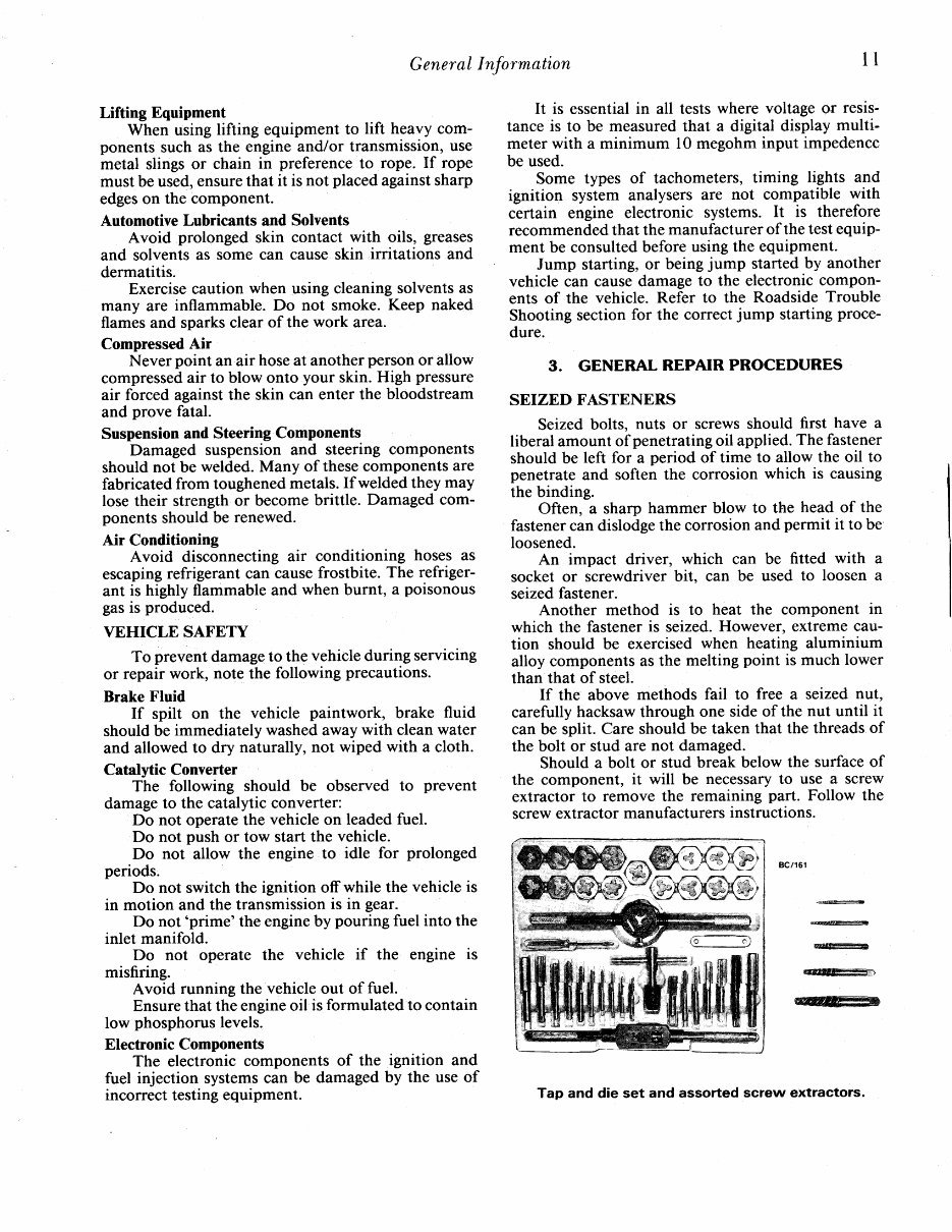
General Information 1l Lifting Equipment When using lifting equipment to lift heavy com- ponents such as the engine and/or transmission, use metal slings or chain in preference to rope. If rope must be used, ensure that it is not placedagainstsharp edges on the component. Automotive Lubricants and Solvents Avoid prolonged skin contact with oils, greases and solvents as some can cause skin irritations and dermatitis. Exercisecaution when using cleaning solventsas many are inflammable. Do not smoke. Keep naked flamesand sparksclear of the work area. Compressed Air Never point an air hose at another personor allow compressed air to blow onto your skin. High pressure air forced againstthe skin can enter the bloodstream and prove fatal. Suspension and Steering Components Damaged suspension and steering components should not be welded. Many of thesecomponentsare fabricatedfrom toughened metals.If welded they may lose their strength or become brittle. Damaged com- ponents should be renewed. Air Conditioning Avoid disconnecting air conditioning hoses as escaping refrigerant can causefrostbite. The refriger- ant is highly flammable and when burnt, a poisonous gasis produced VEHICLE SAFETY To prevent damage to the vehicle during servicing or repair work, note the following precautions. Brake Fluid If spilt on the vehicle paintwork, brake fluid should be immediately washedaway with clean water and allowed to dry naturally, not wiped with a cloth. Catalytic Converter The following should be observed to prevent damage to the catalytic converter: Do not operate the vehicle on leaded fuel. Do not push or tow start the vehicle. Do not allow the engine to idle for prolonged periods. Do not switch the ignition off while the vehicle is in motion and the transmission is in gear. Do not'prime'the engine by pouring fuel into the inlet manifold. Do not operate the vehicle if the engine is misfiring. Avoid running the vehicle out of fuel. Ensure that the engineoil is formulated to contain low phosphoruslevels. ElectronicComponents The electronic components of the ignition and fuel injection systems can be damagedby the use of incorrect testing equipment. It is essentialin all tests where voltage or resrs- tance is to be measuredthat a digital display multi- meter with a minimum l0 megohminput impedence be used. Some types of tachometers,timing lights and ignition system analysers are not compatible with certain engine electronic systems. It is therefore recommended that the manufacturerof the test equip- ment be consulted before using the equipment. Jump starting, or being jump started by another vehicle can causedamageto the electronic compon- ents of the vehicle. Refer to the Roadside Trouble Shooting section for the correct jump starting proce- dure. 3. GENERAL REPAIR PROCEDURES SEIZED FASTENERS Seized bolts, nuts or screws should first have a liberal amount of penetratingoil applied. The fastener should be left for a period of tirne to allow the oil to penetrate and soften the corrosion which is causing the binding. Often, a sharp hammer blow to the head of the fastener can dislodgethe corrosion and permit it to be loosened. An impact driver, which can be fitted with a socket or screwdriver bit, can be used to loosen a seizedfastener. Another method is to heat the component in which the fastener is seized.However, extreme cau- tion should be exercised when heating aluminium alloy componentsas the melting point is much lower than that of steel. If the above methods fail to free a seized nut, carefully hacksawthrough one side of the nut until it can be split. Care should be taken that the threads of the bolt or stud are not damaged. Should a bolt or stud break below the surfaceof the component, it will be necessary to use a screw extractor to remove the remaining part. Follow the screwextractor manufacturersinstructions. BC/161 @4 dffi @ffi? WW t ffi@>,$wst'-.ffi, Tap and die set and assorted screw extractors. Not for distribution outside of AllCarManuals.com
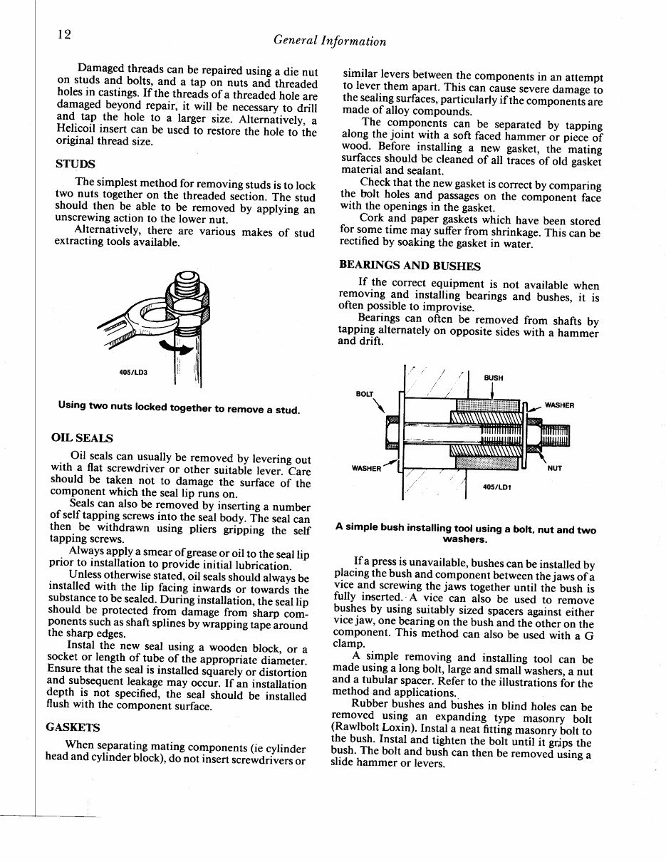
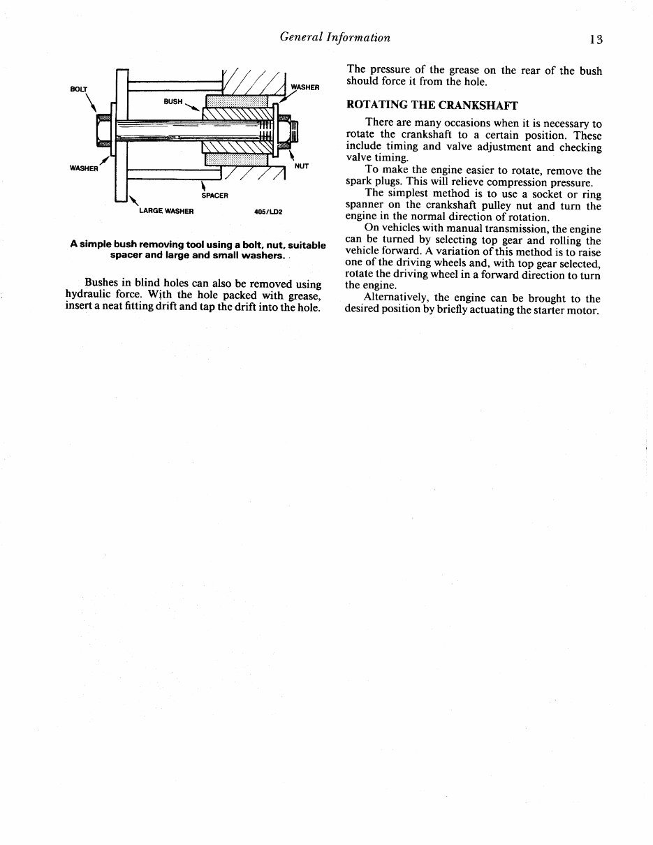
General Information Damaged threads can be repaired using a die nut on studs and bolts, and a tap on nuts and threaded holes in castings. If the threadsof a threaoJo t tte are damaged leyon{ repair, it will be necesrurv io AriU 31d tap the hole to u larger size. Alternatively, a Helicoil insert can be usedlo restore the hole to the original thread size. STUDS The simplestmethod for removing studsis to lock tyo lyts together on the threaded section. The stud should then be able to be removed by applyirrg "r, unscrewingaction to the lower nut. Alternatively, there are various makes of stud extracting tools available. Using two nuts locked together to remove a stud. OIL SEALS Oil seals can usually be removed by levering out with a flat screwdriver or other suitabie lever. care should be taken not to damage the surface of the component which the seallip runs on. Seals can also be removeo uy inserting a number of self tapping screws into rhe s"il body. ii; seatcan then be withdrawn using pliers gripping- ihe self tapping screws. . Always apply a smear ofgrease or oil to the seal lip prior to installation to prorride initial tuuricaiiln. unless otherwisestated, oil seals should ahvays be installed with the lip facing inwards or towards the substance to be sealed. During installation, the seal lip should be protected from dimage from .tt"rp com- ponents suchas shaft splines by wrapping tape iround the sharp edges. Instal the new_ seal using a wooden block, or a socket or length of tube of rh"e "ppi"p.i"tr JilL"r.r. Ensurethat the sealis installed squarity or distortion and subsequent leakage may occ.rr. If an initaliation 9"pJh is- not specified, rhe seal shouto u. -iirtalled flush with the component surface. GASKETS . Ih"," separating mating components(ie cylinder headand cylinder block), do not rnsertscrewdrivers or similar levers betweenthe components in an attempt to lever them apart. This can cause severe damageto the sealingsurfaces, particularly if the.o-pon.nts are made of alloy compounds. . Th9 components can be separated by tapping along tLe ioint with a soft faced hu-mer or piece of wood. Before installing a new gasket, the mating surfaces should be cleanedof a[ Iraces of old gaskel material and sealant. check that the new gasket is correct by comparing the bolt holes and passages on the componen't face with_the openingsin the fasket. ^ cork and paper gask-ets which have been stored tor sometime may suffer from shrinkage. This can be rectified by soaking the gasket in water. BEARINGS AND BUSHES If the correct equipment is not available when removing and installing bearings and bushes, it is often possible to improvise. Bearings can often be removed from shafts by tapping alternately on opposite sides with a hammer and drift. A simple bush instailing tool using a bort,nut and two washers. _ Ifu press is unavailable, bushes can be instailedby placing the bush and component between the jaws of a vice and screwingthe jaws together until th6 6ush is fully inserted. A vice can alio be used to rlmove bushesby using suitably sized spacers against either vicejaw, one bearingonthe bush ano trrittrrei on the component. This method can also be used with a G clamp. A simple removing and installing tool can be ma$e usinq a long bolt, large and small-washers, a nut and-atubular spacer. Refei to the illustrations-for the method and applications. Rubber bushes and bushes in blind holes can be lgmoyed- gsing . a3 expanding type masonry bolt (Rawlbolt Loxin). Instal a neat fitting -u*ry6olt to the bush. Insral and tighten the boliuntillirir,ip, tt" bush.The bolt and bush can then be remov"i.*i"g u slide hammer or levers. Not for distribution outside of AllCarManuals.com
General Information l3 LARGE \I/ASHER A simple bush removingtool using a bolt, nut, suitable spacerand large and small washers. . Bushes in blind holes can also be removed using hydraulic foqce, With the hole packed with grease, insert a neat fitting drift and tap the drift into the hole. The pressure of the grease on the rear of the bush should force it from the hole. ROTATING THE CRANKSHAFT There are many occasions when it is necessary to rotate the crankshaft to a certain position. These include timing and valve adjustment and checking valve timing. To make the engine easier to rotate, remove the spark plugs. This will relieve compression pressure. The simplest method is to use a socket or ring spanner on the crankshaft pulley nut and turn the enginein the normal direction of rotation. On vehicles with manual transmission,the engine can be turned by selecting top gear and rolling the vehicle forward. A variation of this method is toiaise one of the driving wheelsand, with top gear selected, rotate the driving wheel in a forward direction to turn the engine. Alternatively, the engine can be brought to the desired position by briefly actuatingthe starter motor. Not for distribution outside of AllCarManuals.com
You're Reading a Preview
What's Included?
Lifetime Access
Fast Download Speeds
Online & Offline Access
Access PDF Contents & Bookmarks
Full Search Facility
Print one or all pages of your manual
$33.99
1988-1993 Holden Commodore VN VP Calais Service & Repair Manual
The Holden Commodore 1988-1993 VN VP Calais Workshop Manual is a comprehensive guide for owners and enthusiasts of these classic cars. With detailed instructions and diagrams, this manual provides step-by-step procedures for maintenance, repairs, and servicing.
Designed specifically for the Holden Commodore models produced between 1988 and 1993, including the Calais variant, this workshop manual covers a wide range of topics. Whether you're a DIY enthusiast or a professional mechanic, this manual is an invaluable resource for keeping your Commodore in top condition.
Key features of the Holden Commodore 1988-1993 VN VP Calais Workshop Manual include:
Diagnostic procedures and troubleshooting guides
Engine, transmission, and drivetrain maintenance and repair
Electrical system troubleshooting and wiring diagrams
Suspension, steering, and braking system maintenance
Body and interior repairs
Specifications and technical data
Whether you're performing routine maintenance or tackling a major repair, this workshop manual provides the guidance and information you need. With clear instructions and illustrations, even complex procedures are made easy to understand.
Invest in the Holden Commodore 1988-1993 VN VP Calais Workshop Manual today and ensure the longevity and performance of your classic Holden Commodore.
Reviews
Q&A
Recently Viewed
5,521,897Happy Clients
2,594,462eManuals
1,120,453Trusted Sellers
15Years in Business
Price:
Actual Price:
1988-1993 Holden Commodore VN VP Calais Service & Repair Manual


 Lifetime Access




