

2002-2011 Holden Barina Service & Repair Manual
What's Included?
Fast Download Speeds
Offline Viewing
Access Contents & Bookmarks
Full Search Facility
Print one or all pages of your manual

2009 Chevrolet Aveo | Aveo, Wave, G3, Barina (VIN S/T) Service Manual | Brakes | Antilock Brake System |
Specifications | Document ID: 2038959
Fastener Tightening Specifications
Application
Specification
Metric English
Brake Pipe Nuts 22 N·m 16 lb ft
Brake Pressure Modulator Valve (BPMV) Nuts 15 N·m 11 lb ft
Front Wheel Speed Sensor Bolt 8 N·m 71 lb in
Rear Wheel Speed Sensor Bolt 8 N·m 71 lb in
© 2010 General Motors Corporation. All rights reserved.
Page 1 of 1 Document ID: 2038959
7/5/2010 http://localhost:9001/si/showDoc.do?docSyskey=2038959&pubCellSyskey=940&pubObjS...

2009 Chevrolet Aveo | Aveo, Wave, G3, Barina (VIN S/T) Service Manual | Brakes | Antilock Brake System |
Specifications | Document ID: 2038960
ABS Component Specifications
Application
Specification
Metric English
Antilock Brake System (ABS) Main Relay Operation Voltage 9-16 V
Antilock Brake System (ABS) Type 4 Channel 4 Sensor
Speed Ring
l Inside Diameter - Front 69.6 mm 2.7401 in
l Inside Diameter - Rear 58 mm 2.2835 in
l Outside Diameter - Front 83.7 mm 3.2952 in
l Outside Diameter - Rear 69 mm 2.7165 in
l Tooth Volume of the Speed Ring (Front)
l Tooth Volume of the Speed Ring (Rear)
47 EA
40 EA
Wheel Speed Sensor - Resistance 1,215-1,485 Ω
© 2010 General Motors Corporation. All rights reserved.
Page 1 of 1 Document ID: 2038960
7/5/2010 http://localhost:9001/si/showDoc.do?docSyskey=2038960&pubCellSyskey=1210&pubObj...

2009 Chevrolet Aveo | Aveo, Wave, G3, Barina (VIN S/T) Service Manual | Brakes | Antilock Brake System |
Repair Instructions | Document ID: 2038972
Antilock Brake System Automated Bleed Procedure
Bleeding the ABS System
Perform a manual or pressure bleeding procedure. Refer to Hydraulic Brake System Bleeding . If the
desired brake pedal height results are not achieved, perform the automated bleed procedure
below.
The procedure cycles the system valves and runs the pump in order to purge the air from the
secondary circuits normally closed off during normal base brake operation and bleeding. The
automated bleed procedure is recommended when air ingestion is suspected in the secondary
circuits, or when the BPMV has been replaced.
Automated Bleed Procedure
Caution: The Auto Bleed Procedure may be terminated at any time during the process by
pressing the EXIT button. No further Scan Tool prompts pertaining to the Auto Bleed
procedure will be given. After exiting the bleed procedure, relieve bleed pressure and
disconnect bleed equipment per manufacturers instructions. Failure to properly relieve
pressure may result in spilled brake fluid causing damage to components and painted
surfaces.
1. Raise the vehicle on a suitable support. Refer to Lifting and Jacking the Vehicle .
2. Remove all four tire and wheel assemblies. Refer to Tire and Wheel Removal and Installation .
3. Inspect the brake system for leaks and visual damage. Refer to Brake Pipe and Hose
Inspection or Symptoms - Hydraulic Brakes . Repair or replace as needed.
4. Inspect the battery state of charge. Refer to Battery Inspection/Test .
5. Install a scan tool.
6. Turn ON the ignition, with the engine OFF.
7. With the scan tool, establish communications with the EBCM. Select Special Functions. Select
Automated Bleed from the Special Functions menu.
8. Bleed the base brake system. Refer to Hydraulic Brake System Bleeding .
9. Follow the scan tool directions until the desired brake pedal height is achieved.
10. If the bleed procedure is aborted, a malfunction exists. Perform the following steps before
resuming the bleed procedure:
11. When the desired pedal height is achieved, press the brake pedal in order to inspect for
firmness.
12. Remove the scan tool.
13. Install the tire and wheel assemblies. Refer to Tire and Wheel Removal and Installation .
14. Inspect the brake fluid level.
15. Road test the vehicle while inspecting that the pedal remains high and firm.
• If a DTC is detected, refer to Diagnostic Trouble Code (DTC) List - Vehicle and diagnose
the appropriate DTC.
• If the brake pedal feels spongy, perform the conventional brake bleed procedure again.
Refer to Hydraulic Brake System Bleeding .
© 2010 General Motors Corporation. All rights reserved.
Page 1 of 1 Document ID: 2038972
7/5/2010 http://localhost:9001/si/showDoc.do?docSyskey=2038972&pubCellSyskey=1238&pubObj...
2009 Chevrolet Aveo | Aveo, Wave, G3, Barina (VIN S/T) Service Manual | Brakes | Antilock Brake System |
Repair Instructions | Document ID: 2038940
Brake Pressure Modulator Valve Assembly Replacement
Removal Procedure
Warning: Refer to Battery Disconnect Warning in the Preface section.
1. Disconnect the negative battery cable. Refer to Battery Negative Cable Disconnection and
Connection .
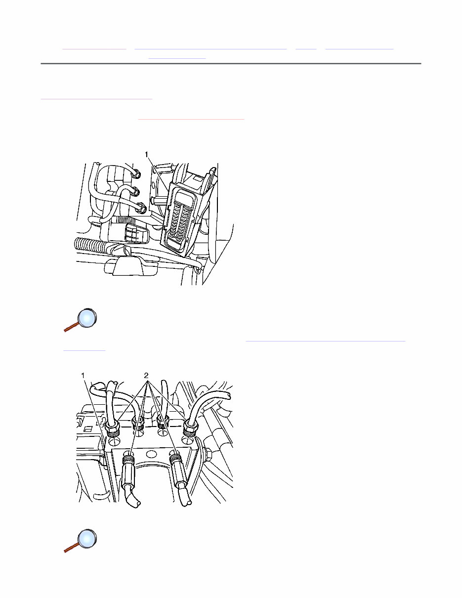
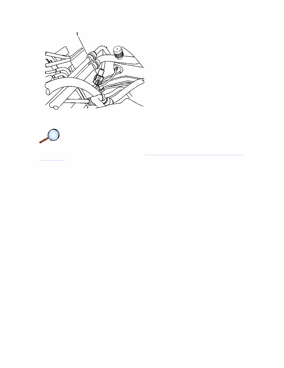
2. Disconnect the electronic brake control module (EBCM) connector (1).
© 2010 General Motors Corporation. All rights reserved.
Page 1 of 3 Document ID: 2038940
7/5/2010 http://localhost:9001/si/showDoc.do?docSyskey=2038940&pubCellSyskey=1199&pubObj...
Note: Take care not to allow air into the hydraulic unit or into the brake pipes from the
master cylinder. If air gets into the hydraulic unit, it will require a bleeding procedure using a
scan tool programmed for the ABS 5.3 system. As long as no air enters the hydraulic unit, a
simple bleeding procedure is all the system will require.
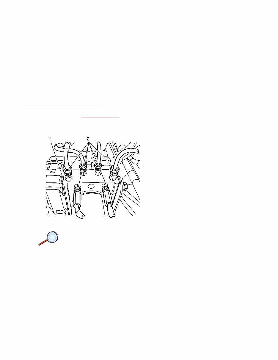
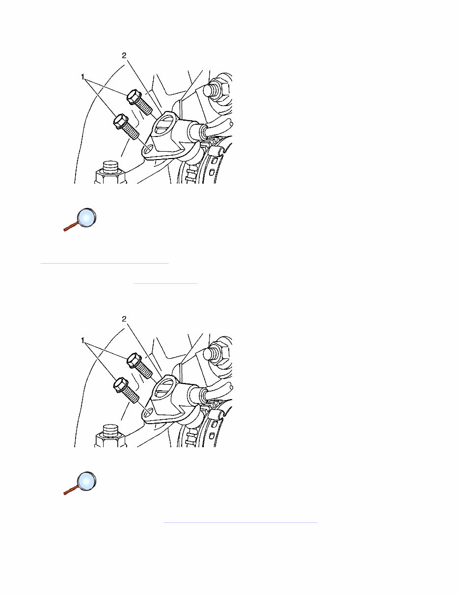
3. Remove the brake pipes from the brake pressure modulator valve (BMPV) assembly.
4. Plug the brake pipes.
5. Loosen the mounting nuts (2) on the BPMV assembly (1).
6. Position the brake pipes aside far enough to allow for lifting the BPMV assembly from the
mounting bracket. It may be necessary to loosen the brake pipes on the master cylinder to
allow for moving those pipes out of the way.
7. Remove the BPMV assembly from the mounting bracket.
Installation Procedure
Caution: Refer to Fastener Caution in the Preface section.
1. Install the BPMV assembly (1) into the mounting bracket. Secure with two nuts (2) and
tighten to 15 N·m (11 lb ft).
2. Remove the plugs from the brake pipes and connect the brake pipes to the BPMV
assembly (1) and tighten to 22 N·m (16 lb ft).
Page 2 of 3 Document ID: 2038940
7/5/2010 http://localhost:9001/si/showDoc.do?docSyskey=2038940&pubCellSyskey=1199&pubObj...
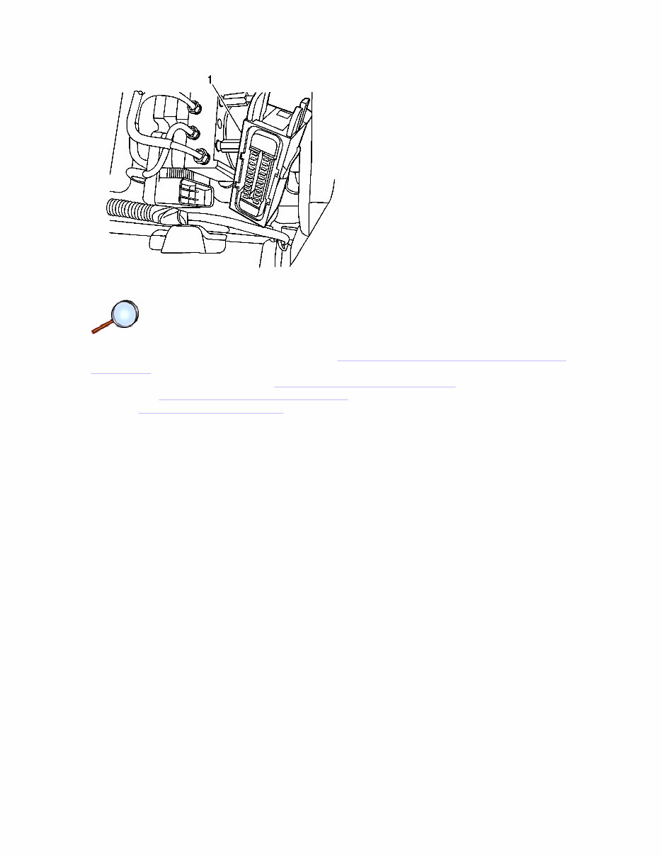
3. Connect the EBCM connector (1).
4. Connect the negative battery cable. Refer to Battery Negative Cable Disconnection and
Connection .
5. Bleed the brake system. Refer to Hydraulic Brake System Bleeding .
6. Perform the Diagnostic System Check - Vehicle .
7. Refer to Control Module References for programming and setup information.
Page 3 of 3 Document ID: 2038940
7/5/2010 http://localhost:9001/si/showDoc.do?docSyskey=2038940&pubCellSyskey=1199&pubObj...
2009 Chevrolet Aveo | Aveo, Wave, G3, Barina (VIN S/T) Service Manual | Brakes | Antilock Brake System |
Repair Instructions | Document ID: 2038925
Front Wheel Speed Sensor Replacement
Removal Procedure
Warning: Refer to Battery Disconnect Warning in the Preface section.
1. Disconnect the negative battery cable. Refer to Battery Negative Cable Disconnection and
Connection .
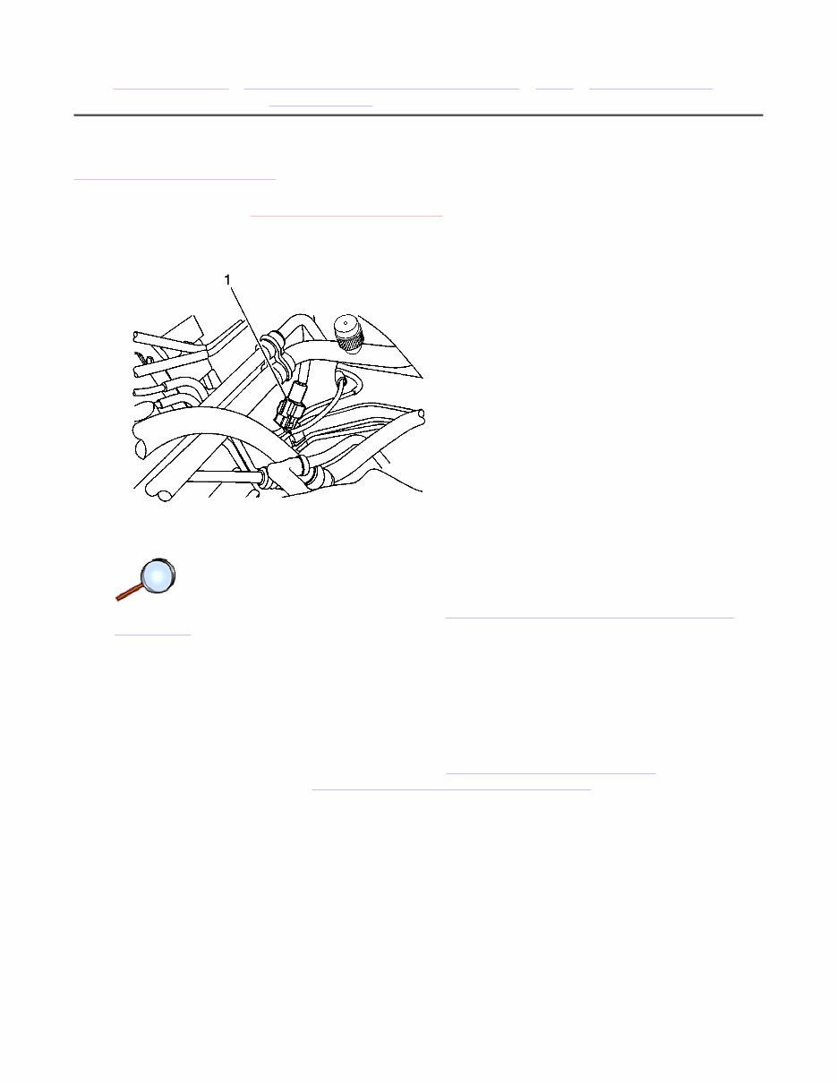
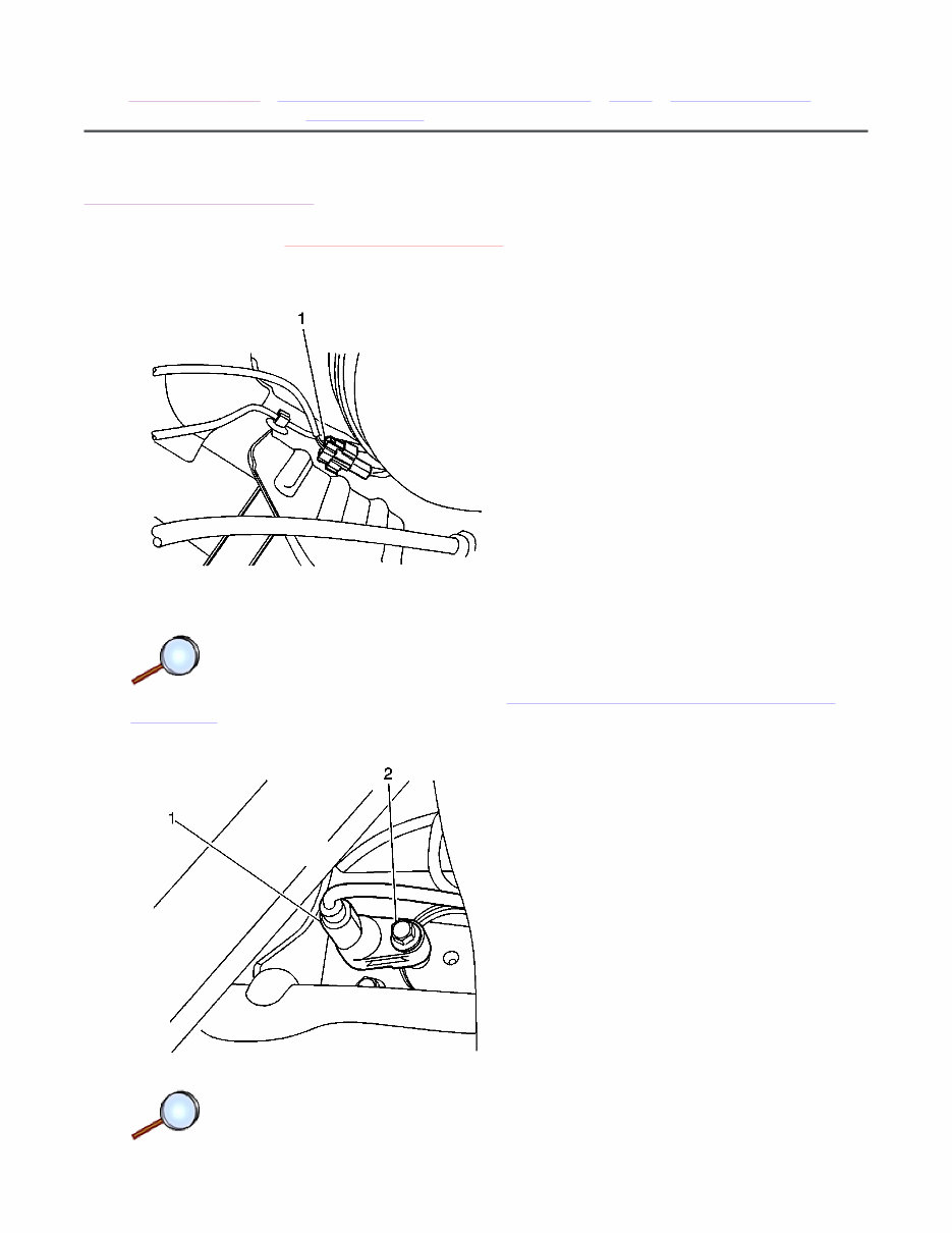
2. Disconnect the front wheel speed sensor electrical connector (1).
Danger: To avoid any vehicle damage, serious personal injury or death when major
components are removed from the vehicle and the vehicle is supported by a hoist, support
the vehicle with jack stands at the opposite end from which the components are being
removed and strap the vehicle to the hoist.
3. Raise and suitably support the vehicle. Refer to Lifting and Jacking the Vehicle .
4. Remove the wheel. Refer to Tire and Wheel Removal and Installation .
© 2010 General Motors Corporation. All rights reserved.
Page 1 of 3 Document ID: 2038925
7/5/2010 http://localhost:9001/si/showDoc.do?docSyskey=2038925&pubCellSyskey=1415&pubObj...
5. Remove the bolts (1) and the front wheel speed sensor (2) from the steering knuckle.
Installation Procedure
Caution: Refer to Fastener Caution in the Preface section.
1. Install the front wheel speed sensor (2) to the steering knuckle. Secure it with the bolts (1)
and tighten to 8 N·m (71 lb in).
2. Install the wheel. Refer to Tire and Wheel Removal and Installation .
3. Lower the vehicle.
Page 2 of 3 Document ID: 2038925
7/5/2010 http://localhost:9001/si/showDoc.do?docSyskey=2038925&pubCellSyskey=1415&pubObj...
4. Connect the front wheel speed sensor electrical connector (1).
5. Connect the negative battery cable. Refer to Battery Negative Cable Disconnection and
Connection .
Page 3 of 3 Document ID: 2038925
7/5/2010 http://localhost:9001/si/showDoc.do?docSyskey=2038925&pubCellSyskey=1415&pubObj...
2009 Chevrolet Aveo | Aveo, Wave, G3, Barina (VIN S/T) Service Manual | Brakes | Antilock Brake System |
Repair Instructions | Document ID: 2154891
Rear Wheel Speed Sensor Replacement
Removal Procedure
Warning: Refer to Battery Disconnect Warning in the Preface section.
1. Disconnect the negative battery cable. Refer to Battery Negative Cable Disconnection and
Connection .
2. Disconnect the rear wheel speed sensor electrical connector (1).
© 2010 General Motors Corporation. All rights reserved.
Page 1 of 3 Document ID: 2154891
7/5/2010 http://localhost:9001/si/showDoc.do?docSyskey=2154891&pubCellSyskey=1416&pubObj...
You're Reading a Preview
What's Included?
Fast Download Speeds
Offline Viewing
Access Contents & Bookmarks
Full Search Facility
Print one or all pages of your manual
$41.99
Viewed 84 Times Today


Secure transaction
What's Included?
Fast Download Speeds
Offline Viewing
Access Contents & Bookmarks
Full Search Facility
Print one or all pages of your manual
$41.99
The Holden Barina Complete Workshop Service Repair Manual is a comprehensive guide covering various models from 2002 to 2011. It provides detailed step-by-step instructions, diagrams, illustrations, and specifications for proper maintenance, servicing, and repairs.
- 2002 Holden Barina
- 2003 Holden Barina
- 2004 Holden Barina
- 2005 Holden Barina
- 2006 Holden Barina
- 2007 Holden Barina
- 2008 Holden Barina
- 2009 Holden Barina
- 2010 Holden Barina
- 2011 Holden Barina
Whether you are a professional mechanic or a DIY enthusiast, this manual is a valuable resource for saving time and money on repairs. It caters to basic maintenance tasks and complex repairs, ensuring your Holden Barina remains in top condition.
Acquire the Holden Barina Complete Workshop Service Repair Manual today to take charge of your car's maintenance and repair requirements.


