Preface With the increase of automobile demand in China, our automobile industry also experiences a rapid development. The trucks including SUV, manufactured by Great Wall Motor Co., Ltd, which are sold all over China, are in the leading place in terms of their sales volume, in order to satisfy the demands of various maintain- ing staff, technicians and managing staff of Changcheng Co., Ltd, we compile this maintenance manual accord- ing to the latest technological data. This manual covers six vehicle models including Deer, Safe, Sailor, Sing, So Cool and Pegasus, its main content includes: Part I is general introduction, which introduces the application index of this manual. Part II introduces the chassis system, which mainly includes the technologies of dismantle, inspection, adjustment, repairing, assembly and mount of the clutch, gear box, transfer box, drive shaft, suspension system and automobile axle, braking system and steering system, etc. each operation approach is illustrated with figure, which not only presents the maintenance procedure, but also clearly describes the technical requirements and application limit. Part III introduces the electric system and air-conditioning system of the automobile body, which mainly covers such items as the location and content of protective box, power supply system, starting system, lighting system, combination instrument, backup radar system, wiping and washing system, center control locking and power window system, acoustical equipment system, full wire harness and air-conditioning system, etc. Electric- ity diagrams for those electric systems are given in this manual so as to facilitate the maintaining technicians to find out the problem easily and quickly. Part IV introduces the external and internal body decoration, which mainly covers the dismantling, inspect- ing and assembling requirements of the engine cover, front and rear doors, adhesive strip of body collision avoidance, wheel shield, wrapping angle of wheel-shield and exterior trim panel, front and rear windshields, side-window glass, rear-door glass, rear platform of cargo compartment, rear door, instrument panel, safety belt, seat, tail-fin, luggage rack, and reserve tire bracket etc. The dimensions of vehicle body and frame are also given to maintaining staff for reference during their repairing. During the narrations of each part, items such as troubleshooting, maintenance notice, maintenance data and application limit, fastening torques of bolts and nuts for special purpose, SST, SSM and lubricant materials and so on are also introduced. Various maintenance data are briefed in attachment for reference. Altogether, this manual is comprehensive in content, visual in illustration, clarifying in requirement and plain in language. It can be referred by the maintaining staff, technicians and professional managing staff. Even though we try our best to compile this manual in a strict earnest manner, we cannot guarantee that all contents in this manual are correct. Therefore, users shall not put forward any claim with Great Wall Company according to this manual; we are not in the position to hold the responsibility for the loss caused by usage of this manual. Due to our limited knowledge, it is unavoidable to find error in this manual, any criticism and correction from you is welcomed. The final explanation power for this manual is subject to Great Wall Motor Co., Ltd Compiler May 2006
Service manual for chassis and body General IN Clutch CL Gear box MT Transfer box TF Drive shaft PR Suspension system and automobile axle SA Braking system BR Steering system SR Body electric system BE Air-conditioning system AC Vehicle body BO Maintenance and Up-keeping A Special Tool B
IN-1 Page How to use this manual ................................................. IN-2 Instruction for overall repairing ...................................... IN-4 Body lifting height and support position ........................ IN-5 fk Introduction
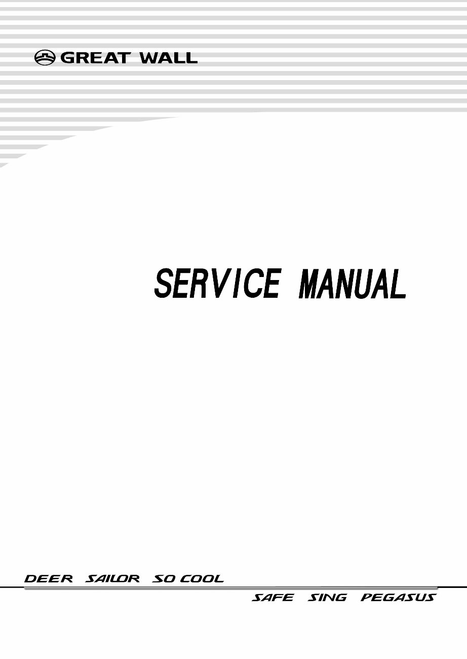
IN-2 How to use this manual In order to help you to look in this manual, we marked the chapter name and main theme at the top of each page. In order to introduce the repairing items to you, we make the index on the first page of each chapter, and notices need to be taken during all repairing operation are also given in the related chapter. Please read these notices carefully before the repairing work. The troubleshooting form for each system will help you to diagnose the system trouble and its cause. We furnish with the repairing approaches for each possible cause in the repairing approach column, which will help you to acquire the solution in a short time. Introduction How to Use This Manual Repairing approach Most repairing operation can begin with referring to these illustrations. These illustrations can help you identify the parts and their coordina- tion situation Example snapping ring front minor half-shaft front speed reducer and differential oil seal-front semi-axle front long semi-axis snapping ring 88 N*m specified torque Parts that cannot be reused after being used
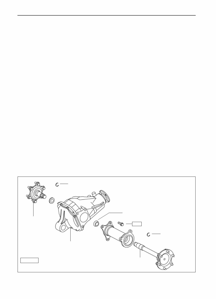
IN-3 Introduction How to Use This Manual Introductionóhow to use this manual The repairing approaches are described step by step: The illustrations show you what to do and at which position. The theme of repairing operation tell you what you need to do. The detailed instruction show you how to accomplish the repairing and introduce to you other related affairs, such as specification, warning etc. Example: Check and adjust the flange bounce (a) Attach the dial indicator seat to the reducer housing, and touch the flange face with the measuring head of dial indicator, run the flange and observe the pendular range of the indicator carefully. Full bounce tolerance of face : 0.10mm Illustration: what to do and at which position Specification This formula can help the experienced technicians find out the failure causes in short time. Overhauling staff can browse the operation theme and refer to the detailed description thereunder where necessary; impor- tant specifications and warnings are written out in boldface. Specification The corresponding specifications are given in boldface in each repairing approach of this manual, which allows the overhauling staff to check the specification while keeping on repairing work. Warning, Notice and Remark Warning written out in boldface means there is possibility of self- injury or harm to others. Notice written out in boldface means there is possibility of damage to parts under repairing. Remarks singled out independently, but not in boldface, serve as supplementary descriptions to help you accomplish the work more efficiently. Vehicle Code There are six vehicle models in this manual, the model codes are as follows: Deer modelDr Sailor modelSL SO COOL modelSK Safe modelSF Sing model SY PEGASUS modelSJ Abbreviation used in this manual A/Cair-conditioner ECUelectronic controller unit SSTspecial service tool 2WDtwo-wheel drive 4WDfour-wheel drive PMãã Topic:what to do ? Detailed introductionz;How to do?
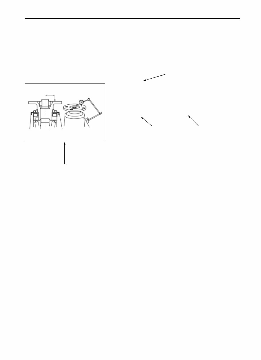
IN-4 Overall Repairing Description 1. Keep the vehicle clean and prevent it from damage with guard plate, seat and floor cover cloth. 2. Put down the dismantled parts in order during the dismantle process so as to facilitate the re- assembly 3. Observe the following items: a) Disconnect the cable cathode from the accumulator terminal before the electric operation;. b) Disconnect the cable from the cathode connected to the vehicle body when check- ing or repairing the accumulator where necessary. c) In order to avoid the damage of terminal post of accumulator, loose the bolts first, then pull up the cable vertically when dismantling, dont wring it or prize it. d) Clean the terminal posts of the accumula- tor with dishcloth, and do not scrape them with file or other similar tools to avoid damage. e) Mount the cable terminal on the post with loosened nut, then fasten the nut. donít tap the terminal onto the post with hammer. f) Be sure to check whether the cover of positive terminal (+) is well located or not. 4. Check all hoses and wire plugs to verify whether they are connected solidly and correctly. 5. Parts that cannot be reused after being used. a) The following parts should be changed with new one regularly: split pin, sealing washer, O-ring and oil seal, etc. b) parts that cannot be reused after being used is marked with in the element figure. 6. Pre-coated parts The pre-coated parts including the bolt and nut are coated with locking seal glue in factory. a) In case the pre-coated parts are moved due to its fastening, loosening or other causes, they must be coated again with the specified seal glue. b) Coating procedure of pre-coated parts 1) Clear away the former seal glue from the screw thread of the said parts. 2) Dry the parts with compressed air. 3) Coat the screw thread of the parts with the specified locking seal glue. c) The pre-coated parts are marked with the in element figure. 7. When necessary, sealing agent or sealing ring to prevent the leakage. 8. Each specification shall be followed strictly. And the torque spanners should be used. 9. Determine the necessity of using the special service tools (SST) or special service materials (SSM) according to the real situation. SST and SSM must be used where necessary and the repairing should be in accordance with the repairing approach. SST list and SSM list are attached to this manual. 10. Be sure to check whether the rated current of the new fuse is correct when changing the fuse. The fuse rated current should not larger than that of securing fitting and the fuse of smaller rated current must not be used. 11. Be careful to hang or support the vehicle on the suitable place when propping up or raising it. a) In case prop up the vehicle at the front or back part, the wheels must be blocked to guarantee the safety work. Introduction Overall Repairing Rescription tighten seal glue
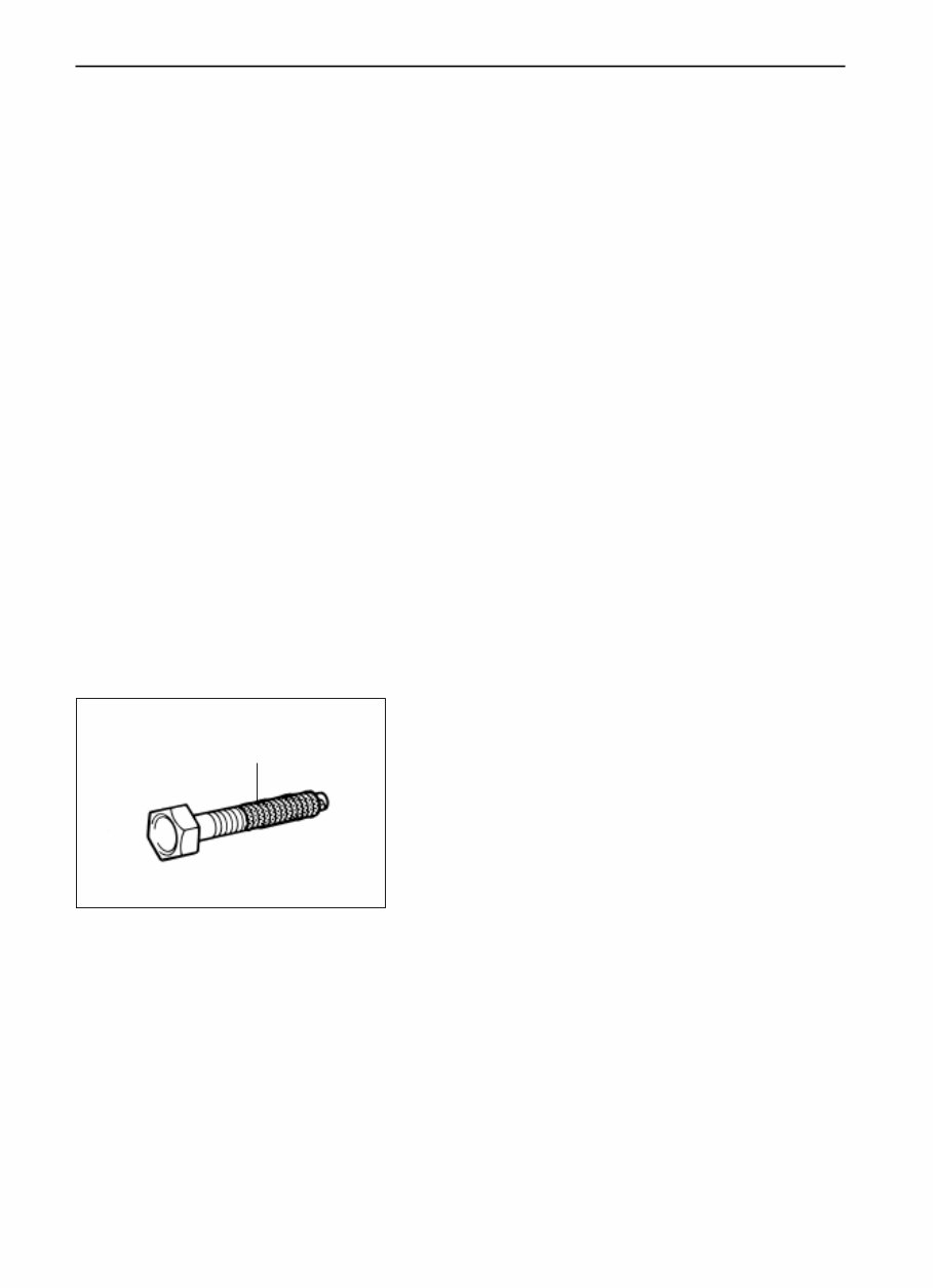
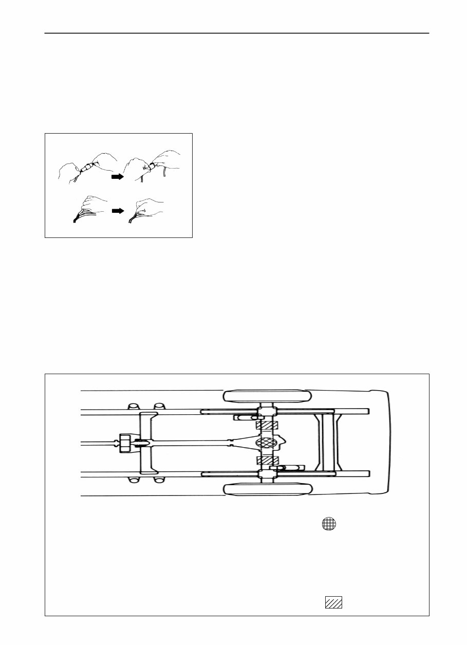
IN-5 Body lifting height and supporting position wrong correct Introduction Body Lifting Height and Supporting Position Jack lifting position ........................................................................................................... Front......the front the beam center Rear..... rear differential Supporting position safety bracket ............................................................................................. front b) The raised vehicle must be supported with the bracket; it is dangerous to conduct the repairing work on the vehicle propped up with one jack, even though such repairing can be finished in short time. 12. The following items shall be taken notice to avoid the parts damage: a) Do not open the covers of ECU and various computers where not necessary absolutely. (if the IC terminal is touched, it be leaded into static damage) . b) Pull the hose at its ends when dismantling it, do not pull it at the center section. c) Pull the wire joint instead of the wire when pulling the joint away. d) Take notice to avoid of the drop of electric parts such as the sensors or repeaters. In case those parts drop to the hard ground, they must be changed instead of being reused. e) Do not use the striking spanner to dismantle or mount the thermostatic switch or thermostatic sensor. f) Plug the needles of the multi-meter into the wire connector carefully when checking its conductance and do not bend the terminals. g) Do not sheath the hose of the vacuum gauge into the very large connector when using the gauge, instead, the stage joint shall be used because once the hose expands, it is possible to lead into the leakage.
CL-1 CL Page Troubleshooting .......................................................... CL-2 Inspection and adjustment of clutch pedal ................... CL-3 Air exhausting of clutch ................................................ CL-3 Clutch master cylinder ................................................ CL-4 Clutch wheel-brake cylinder ......................................... CL-6 Clutch cluster ............................................................... CL-7 Clutch
Whether you're a professional mechanic or a DIY enthusiast, this repair manual equips you with the necessary resources to address vehicle issues. It encompasses comprehensive troubleshooting and replacement procedures, complete with step-by-step instructions, clear images, and exploded-view illustrations.
While your vehicle's durability is undeniable, regular maintenance is essential. Over time, certain parts will wear out and require replacement. This manual provides manufacturer-recommended troubleshooting charts and replacement procedures, enabling you to effectively address your vehicle's needs, save on repairs, and enhance its reliability.
Featuring step-by-step instructions, exploded-view illustrations, and clear images, this manual eliminates the need to sift through numerous pages to locate specific information. Say goodbye to greasy, torn, or misplaced pages. You can conveniently carry, search, screenshot, and bookmark the digital manual, offering a more practical alternative to traditional bound manuals.
Should you prefer a physical copy, you have the option to print it out as well.
Format: .pdf Printable: Yes Language: English Compatibility: Compatible with various electronic devices, including PC, Mac computers, Android and Apple smartphones, and tablets, etc. Requirements: Adobe Reader (free)