

2007-2009 GMC Sierra HD 2500 3500 Pickup Truck Service & Repair Manual
What's Included?
Fast Download Speeds
Offline Viewing
Access Contents & Bookmarks
Full Search Facility
Print one or all pages of your manual
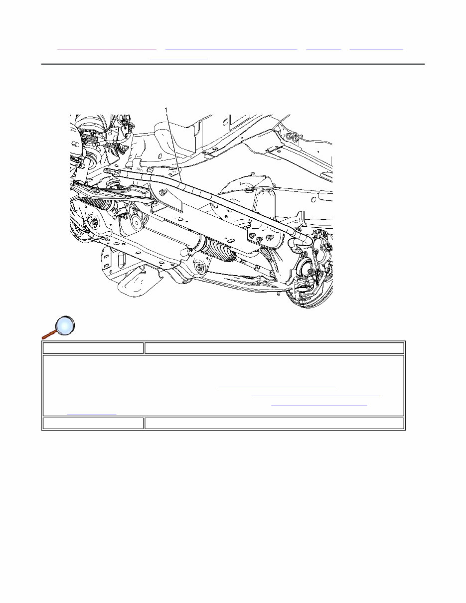
2009 Chevrolet Silverado - 4WD | Sierra, Silverado (VIN C/K) Service Manual | Suspension | Front Suspension |
Repair Instructions | Document ID: 1865385
Stabilizer Shaft Replacement (1500)
Callout Component Name
Preliminary Procedures
1. Raise and support the vehicle. Refer to Lifting and Jacking the Vehicle .
2. Remove the front stabilizer shaft links. Refer to Stabilizer Shaft Link Replacement .
3. Remove the front stabilizer shaft insulators. Refer to Stabilizer Shaft Insulator
Replacement .
1 Front Stabilizer Shaft
© 2010 General Motors Corporation. All rights reserved.
Page 1 of 1 Document ID: 1865385
9/15/2010 http://localhost:9001/si/showDoc.do?docSyskey=1865385&pubCellSyskey=47663&pubO...
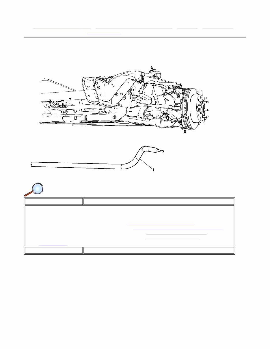
2009 Chevrolet Silverado - 4WD | Sierra, Silverado (VIN C/K) Service Manual | Suspension | Front Suspension |
Repair Instructions | Document ID: 1869385
Stabilizer Shaft Replacement (2500, 3500)
Callout Component Name
Preliminary Procedure
1. Raise and support the vehicle. Refer to Lifting and Jacking the Vehicle .
2. Remove the front tire and wheel. Refer to Tire and Wheel Removal and Installation .
3. Remove the engine shield, if equipped. Refer to Engine Shield Replacement .
4. Remove the stabilizer shaft insulators. Refer to Stabilizer Shaft Insulator
Replacement .
1 Front Stabilizer Shaft
© 2010 General Motors Corporation. All rights reserved.
Page 1 of 1 Document ID: 1869385
9/15/2010 http://localhost:9001/si/showDoc.do?docSyskey=1869385&pubCellSyskey=47663&pubO...
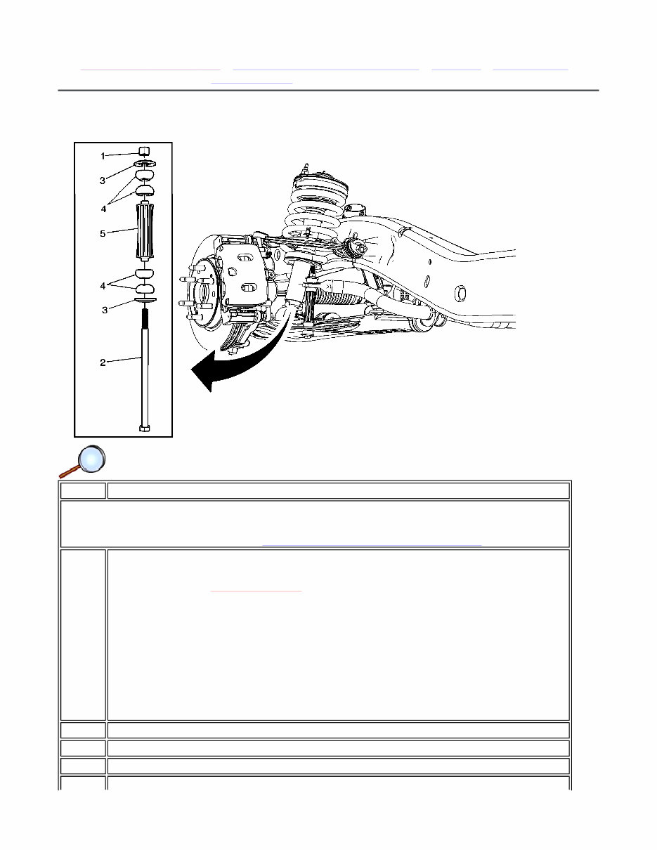
2009 Chevrolet Silverado - 4WD | Sierra, Silverado (VIN C/K) Service Manual | Suspension | Front Suspension |
Repair Instructions | Document ID: 2163681
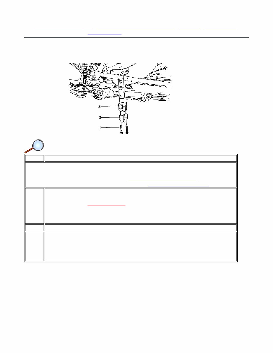
Stabilizer Shaft Link Replacement (1500)
Callout Component Name
Preliminary Procedure
Remove the tire and wheel. Refer to Tire and Wheel Removal and Installation .
1
Stabilizer Shaft Link Nut
Caution: Refer to Fastener Caution in the Preface section.
Procedure
1. Remove all traces of the original adhesive patch.
2. Apply Threadlocker GM P/N 12345382 (Canadian P/N 10953489) BLUE
LOCTITE # 242 on the threads of the bolts.
Tighten
23 N·m (17 lb ft)
2 Stabilizer Shaft Link Bolt
3 Stabilizer Shaft Link Washer (Qty: 2)
4 Stabilizer Shaft Link Insulator (Qty: 4)
© 2010 General Motors Corporation. All rights reserved.
Page 1 of 2 Document ID: 2163681
9/15/2010 http://localhost:9001/si/showDoc.do?docSyskey=2163681&pubCellSyskey=47741&pubO...

5 Stabilizer Shaft Link Spacer
Page 2 of 2 Document ID: 2163681
9/15/2010 http://localhost:9001/si/showDoc.do?docSyskey=2163681&pubCellSyskey=47741&pubO...
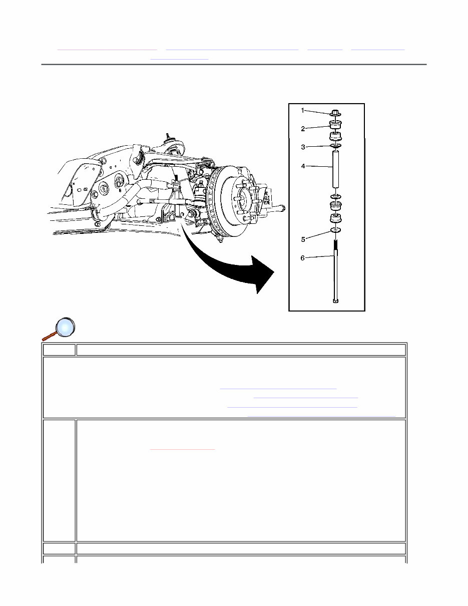
2009 Chevrolet Silverado - 4WD | Sierra, Silverado (VIN C/K) Service Manual | Suspension | Front Suspension |
Repair Instructions | Document ID: 2171208
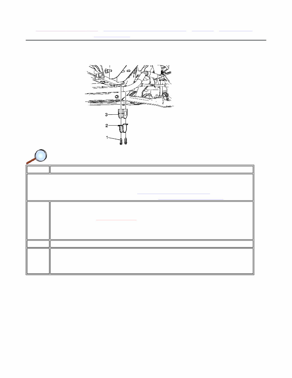
Stabilizer Shaft Link Replacement (2500, 3500)
Callout Component Name
Preliminary Procedure
1. Raise and support the vehicle. Refer to Lifting and Jacking the Vehicle .
2. Remove the engine shield, if equipped. Refer to Engine Shield Replacement .
3. Remove the stabilizer shaft link. Refer to Stabilizer Shaft Link Replacement .
4. Remove the stabilizer shaft insulator. Refer to Stabilizer Shaft Insulator Replacement .
1
Stabilizer Shaft Link Retaining Nut
Caution: Refer to Fastener Caution in the Preface section.
Procedure
1. Remove all traces of the original adhesive patch.
2. Apply Threadlocker GM P/N 12345382 (Canadian P/N 10953489) BLUE
LOCTITE # 242 on the threads of the bolt.
Tighten
23 N·m (17 lb ft)
2 Front Stabilizer Shaft Insulator (Qty: 4)
© 2010 General Motors Corporation. All rights reserved.
Page 1 of 2 Document ID: 2171208
9/15/2010 http://localhost:9001/si/showDoc.do?docSyskey=2171208&pubCellSyskey=47741&pubO...

3 Front Stabilizer Shaft Washer (Qty: 2)
4 Front Stabilizer Shaft Spacer
5 Front Stabilizer Shaft Washer
6 Front Stabilizer Shaft Bolt
Page 2 of 2 Document ID: 2171208
9/15/2010 http://localhost:9001/si/showDoc.do?docSyskey=2171208&pubCellSyskey=47741&pubO...
2009 Chevrolet Silverado - 4WD | Sierra, Silverado (VIN C/K) Service Manual | Suspension | Front Suspension |
Repair Instructions | Document ID: 2163683
Stabilizer Shaft Insulator Replacement (1500)
Callout Component Name
Preliminary Procedure
1. Raise and support the vehicle. Refer to Lifting and Jacking the Vehicle .
2. Remove the engine shield, if equipped. Refer to Engine Shield Replacement .
1
Stabilizer Shaft Clamp Bolt (Qty: 2)
Caution: Refer to Fastener Caution in the Preface section.
Tighten
50 N·m (37 lb ft)
2 Stabilizer Shaft Clamp
3
Stabilizer Shaft Insulator
Tip
Ensure that the slit in the stabilizer shaft insulator is installed toward the rear of the
vehicle.
© 2010 General Motors Corporation. All rights reserved.
Page 1 of 1 Document ID: 2163683
9/15/2010 http://localhost:9001/si/showDoc.do?docSyskey=2163683&pubCellSyskey=47744&pubO...
2009 Chevrolet Silverado - 4WD | Sierra, Silverado (VIN C/K) Service Manual | Suspension | Front Suspension |
Repair Instructions | Document ID: 2171209
Stabilizer Shaft Insulator Replacement (2500, 3500)
Callout Component Name
Preliminary Procedure
1. Raise and support the vehicle. Refer to Lifting and Jacking the Vehicle .
2. Remove the engine shield, if equipped. Refer to Engine Shield Replacement .
1
Stabilizer Shaft Clamp Bolt (Qty: 2)
Caution: Refer to Fastener Caution in the Preface section.
Tighten
50 N·m (37 lb ft)
2 Stabilizer Shaft Clamp
3
Stabilizer Shaft Insulator
Tip
Ensure the slit in the insulator is facing front of the vehicle when installed.
© 2010 General Motors Corporation. All rights reserved.
Page 1 of 1 Document ID: 2171209
9/15/2010 http://localhost:9001/si/showDoc.do?docSyskey=2171209&pubCellSyskey=47744&pubO...

2009 Chevrolet Silverado - 4WD | Sierra, Silverado (VIN C/K) Service Manual | Suspension | Front Suspension |
Repair Instructions | Document ID: 2173359
Lower Control Arm Ball Joint Replacement
Removal Procedure
Note: The following service procedure applies to vehicle equipped with cast iron lower control arms
only. For those vehicles equipped with an aluminum lower control arm, the ball joint is NOT
serviced separately. If the ball joint in the aluminum lower control arm is found to have excessive
wear and is damaged replace the lower control arm as an assembly.
1. Raise and support the vehicle. Refer to Lifting and Jacking the Vehicle .
2. Remove the tire and wheel assembly. Refer to Tire and Wheel Removal and Installation .
3. Remove the lower control arm from the vehicle. Refer to Lower Control Arm Replacement .
4. Place the lower control arm in a vise.
5. Using a chisel, remove the securing crimps from the ball joint body, if equipped.
6. Using a press, remove the ball joint from the lower control arm.
Installation Procedure
Note: Use the outer flange of the ball joint in order to press the ball joint into place.
1. Install the ball joint using a press.
2. Place the lower control arm a bench vise.
Note: Use the replaced ball joint as a reference.
3. Using a punch, install the crimps to the ball joint.
4. Install the lower control arm in the vehicle. Refer to Lower Control Arm Replacement
5. Install the tire and wheel. Refer to Tire and Wheel Removal and Installation .
6. Remove the safety stand and lower the vehicle.
7. Verify the wheel alignment. Refer to Wheel Alignment Specifications .
© 2010 General Motors Corporation. All rights reserved.
Page 1 of 1 Document ID: 2173359
9/15/2010 http://localhost:9001/si/showDoc.do?docSyskey=2173359&pubCellSyskey=47657&pubO...
2009 Chevrolet Silverado - 4WD | Sierra, Silverado (VIN C/K) Service Manual | Suspension | Front Suspension |
Repair Instructions | Document ID: 1869841
Steering Knuckle Replacement (1500)
Removal Procedure
1. Raise and support the vehicle. Refer to Lifting and Jacking the Vehicle .
2. Remove the tire and wheel. Refer to Tire and Wheel Removal and Installation .
3. Remove the wheel drive shaft, if equipped. Refer to Wheel Drive Shaft Replacement .
4. Remove the wheel bearing and hub assembly. Refer to Front Wheel Hub, Bearing, and Seal
Replacement .
5. Remove the outer tie rod end from the knuckle. Refer to Steering Linkage Outer Tie Rod
Replacement .
6. Separate the upper control arm from the knuckle. Refer to Upper Control Arm Replacement .
7. Separate the lower control arm from the knuckle. Refer to Lower Control Arm Replacement .
8. Remove the knuckle from the vehicle.
Installation Procedure
© 2010 General Motors Corporation. All rights reserved.
Page 1 of 2 Document ID: 1869841
9/15/2010 http://localhost:9001/si/showDoc.do?docSyskey=1869841&pubCellSyskey=47664&pubO...
You're Reading a Preview
What's Included?
Fast Download Speeds
Offline Viewing
Access Contents & Bookmarks
Full Search Facility
Print one or all pages of your manual
$41.99
Viewed 46 Times Today


Secure transaction
What's Included?
Fast Download Speeds
Offline Viewing
Access Contents & Bookmarks
Full Search Facility
Print one or all pages of your manual
$41.99
The 2007-2009 GMC Sierra 2500/3500 HD OEM Service & Repair Manual is a comprehensive guide covering maintenance, repair, and troubleshooting specifically for the GMC Sierra 2500 and 3500 HD pickup trucks.
Designed for model years 2007, 2008, and 2009, this manual is an invaluable resource for professional mechanics and DIY enthusiasts alike.
- Detailed step-by-step instructions, diagrams, and illustrations for engine maintenance, transmission repairs, electrical system troubleshooting, and more.
- Covers essential maintenance procedures for both GMC Sierra 2500 HD and GMC Sierra 3500 HD pickup trucks.
- An indispensable tool for keeping your truck in top condition, saving time and reducing repair costs.


