FORWARD The information contained in this service manual has been prepared for the professional automotive technician involved in daily repair oper- ations. Information describing the operation and use of standard and optional equipment is included in the Owner’s Manual provided with the vehicle. Information in this manual is divided into groups. These groups con- tain description, operation, diagnosis, testing, adjustments, removal, installation, disassembly, and assembly procedures for the systems and components. To assist in locating a group title page, use the Group Tab Locator. The solid bar after the group title is aligned to a solid tab on the first page of each group. The first page of the group has a contents section that lists major topics within the group. If you are not sure which Group contains the information you need, look up the Component/System in the alphabetical index located in the rear of this manual. A Service Manual Comment form is included at the rear of this manu- al. Use the form to provide with your comments and suggestions. Tightening torques are provided as a specific value throughout this manual. This value represents the midpoint of the acceptable engi- neering torque range for a given fastener application. These torque values are intended for use in service assembly and installation pro- cedures using the correct OEM fasteners. When replacing fasteners, always use the same type (part number) fastener as removed. Global Electric Motorcars, L.L.C. reserves the right to change testing procedures, specifications, diagnosis, repair methods, or vehicle wiring at any time without prior notice or incurring obligation.
GROUP TAB LOCATOR 0 - INTRODUCTION 2 - SUSPENSION AND STEERING 3 - DRIVETRAIN 4 - BRAKES 5 - ELECTRICAL 6 - WHEELS & TIRES 7 - BODY 8 - WORD INDEX
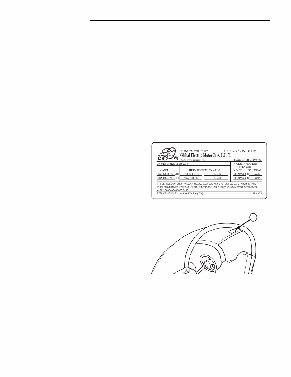
0 - 2 INTRODUCTION VEHICLE IDENTIFICATION/SAFETY CERTIFICATION LABEL Description A label, containing the Vehicle Identification Number (VIN) and safety certification, is located above the bench seat on the underside of the rear roof panel on the driver's side. The information on the label includes: • Vehicle Identification Number • Month and year of manufacture • Gross Vehicle Weight Rating • Gross Front and Rear Axle Ratings • Wheel size • Tire size • Cold tire pressure Figure 1 - VIN/Certification Label Figure 2 - VIN/Certification Location 1. VIN/Certification Label Location (Typical - 2-passenger model shown) NOTE: The last six digits of the VIN are also stamped into the rear support for the bench seat cushion. USING THIS MANUAL Appropriate service methods and proper repair proce- dures are essential for the safe, reliable operation of your vehicles, as well as the safety of the individual doing the work. This service manual provides general directions for accomplishing service and repair work with recom- mended techniques. Following them will help assure reliability. There are numerous variations in procedures, techniques, tools, and parts for servicing your vehicle, as well as in the skill levels of the individuals doing the work. This manual cannot possibly anticipate all such variations and provide advice or cautions for each. Accordingly, anyone who departs from the instructions provided in this manu- al must first establish that he/she compromises neither their personal safety nor vehicle integrity by their choice of methods, tools, or parts. GENERAL WARNINGS The following should be followed whenever you are working on your vehicle: • Always wear safety glasses for eye protection. • Use safety stands whenever a procedure requires you to be under the vehicle. • Be sure that the Ignition Switch is always in the "OFF" position and that the "KEY" is removed. • Be sure to switch the 72-volt Master Disconnect to "OFF". • Set the Parking Brake and place wood blocks (4" x 4" or larger) to the front and rear surfaces of the tires to restrain the vehicle from movement. • Do not smoke while working on your vehicle. Batteries produce hydrogen gas that is extremely flammable and will explode upon exposure to any ignition source. • Remove rings, watches, loose jewelry, and loose clothing when working on your vehicle to avoid injury. NOTE: The terms right-hand (RH) and left- hand (LH) are relative to one sitting in the driver's seat. Therefore, right-hand refers to the passenger side, and left-hand refers to the driver's side of the vehicle. 0001 1
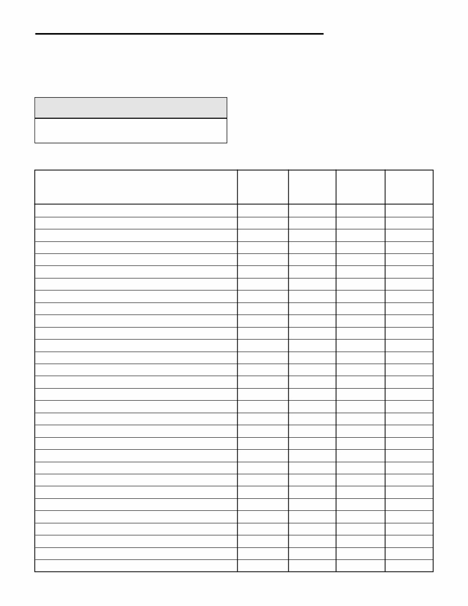
INTRODUCTION 0 - 3 Fasteners and torque specifications references in this Service Manual are identified SAE format. During any maintenance or repair procedure, it is impor- tant to salvage all fasteners (nuts, bolts, etc.) for re- assembly. If the fastener is not salvageable, a fastener of equivalent specification must be used. NOTE: Nylon lock nuts must always be replaced. TORQUE SPECIFICATIONS DESCRIPTION THREAD Use INCH- FOOT- SIZE Loctite® POUNDS POUNDS 242 Battery Cables to Battery Post NO 70 --- Brake line to Wheel/Master Cylinder NO --- 37 Brake Master Cylinder to Frame 5/16 - 18 NO 225 --- Brake Pedal Assembly to Frame 5/16 - 18 NO 225 --- Brake Pedal to Push Rod 3/8 - 16 NO --- 30 Brake, Drum Assembly to Steering Knuckle M8 x 1.25 NO 225 --- Brake, Parking - Cable Mount to Rear Suspension 1/2" x 13 NO --- 90 Control Arm to Frt. Suspension Frame M12 x 1.75 NO --- 60 Differential to Frt. Suspension Frame 5/16" -- 18 NO 225 --- Front Suspension Frame to Frame (Lower) M12 x 1.75 YES --- 60 Front Suspension Frame to Frame (Upper) 3/8 - 16 YES --- 30 Half Shaft to Drum Brake Assembly M16 x 1.5 YES --- 74 King Pin Pinch Bolt M6 - 1 YES 65 --- Motor to Differential 1/4 - 20 YES 65 --- Rack & Pinion to Frt. Suspension Frame M8 x 1.25 NO 225 --- Rear Suspension Frame to Frame M12 x 1.75 NO --- 60 Seat Belt D-Ring to Frame NO --- 60 Seat Belt End to Frame NO --- 60 Seat Belt Latch Assembly to Frame NO --- 60 Seat Belt Latch Assembly to Bracket - Bucket Seat NO --- 60 Seat Belt Retractor to Bracket - Bucket Seat NO --- 60 Seat Belt Retractor to Frame - Bench Seat NO --- 60 Shock Absorber Lower Bolt M12 x 1.75 NO --- 60 Shock Absorber Upper Bolt M12 x 1.75 NO --- 60 Steering Column Pinch Bolt 3/8 - 16 NO --- 30 Steering Column to Dash Frame 5/16 - 18 NO 225 --- Steering Wheel to Steering Shaft NO 225 Tie Rod Stud Nut M10 x 1.5 NO --- 35 Wheel Lug Nuts M10 x 1.5 NO --- 50 Yoke to Control Arm M12 x 1.75 NO --- 60 FASTENER USAGE Description WARNING! Use of an incorrect fastener may result in component damage or personal injury.
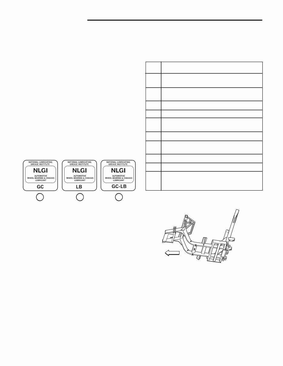
0 - 4 INTRODUCTION MAINTENANCE SCHEDULES Perform the following inspections, and correc- tions as necessary, on a monthly basis. Item Description 1. Check all six batteries for proper water levels. 2. Check battery terminals for tight connections. 3. Check battery terminals for corrosion. 4. Check tires for correct PSI and wear. 5. Check zerc fittings on each kingpin and grease if needed. 6. Check for proper operation of hand brake. 7. Check Master cylinder for proper brake fluid levels. 8. Check brake lines for leaks. 9. Check seat belts for proper operation. 10. Check headlights, horn, turn signals, windshield wiper and brake lights for proper operation. HOISTING AND JACKING Figure 4 - Hoisting/Jacking Locations A vehicle can be lifted with: • A single-post frame-contact hoist • A twin-post, chassis hoist • A ramp-type drive-on hoist. NOTE: When a frame-contact type hoist is used, verify that the lifting pads are posi- tioned properly. PARTS AND LUBRICANT RECOMMENDATION When service is required, GEM recommends that only GEM replacement parts be used. GEM provides the best engineered products for servicing GEM vehicles. Description - Lubricants and Grease Only lubricants bearing designations defined by The Society for Automotive Engineers (SAE) should be used to service a GEM vehicle. The National Lubricating Grease Institute (NLGI) rates lubricating grease for quality and usage. All approved products have the NLGI symbol (Fig. 3) on the label. At the bottom of the symbol is the usage and quality identi- fication letters. The letter "G" identifies wheel-bearing lubricant. The letter "L" identifies chassis lubricant. The letter following the usage letter indicates the quality of the lubricant. The following symbols indicate the high- est quality. Figure 3 - NLGI Symbols 1. Wheel Bearing Lubrication 2. Chassis Lubrication 3. Chassis and Wheel Bearing Lubrication Description - Differential Use SAE 30 weight motor oil. Description - King Pin Lubricant Use only grease with NLGI "L" or "LB" symbol. Description - Brake Fluid Use only DOT3 brake fluid from an unopened container when filling the master cylinder to prevent contaminants from entering the brake system. 0080 1 2 3 0066 FWD
INTRODUCTION 0 - 5 WARNING! The hoisting and jack lifting points provided are for a complete vehicle. When a chassis or drivetrain component is removed from a vehicle, the center of gravity is altered making some hoisting conditions unstable. Properly support or secure vehicle to hoisting device when these conditions exist. CAUTION! Do not attempt to lift a vehicle with a floor jack positioned under: • An axle tube • Body side panel or sill • Front control arm When properly positioned, a floor jack can be used to lift a GEM vehicle. Support the vehicle in the raised position with jack stands at the locations indicated.
2002-2004 GEM E825 Electric Cars Service & Repair Manual
Manuals Included:
2002-2004 GEM E825 Service & Repair Manual
2002-2004 GEM E825 Owner’s Manual
2002-2004 GEM E825 Parts Catalog
This 2002-2004 GEM E825 Electric Cars Service & Repair Manual provides all the critical service procedures, diagnostics, and maintenance data needed for your electric GEM vehicle. Designed for both professional technicians and knowledgeable DIYers, this manual covers major components including suspension, drivetrain, braking systems, and electrical schematics.
Detailed diagrams and clear repair instructions make it easier to troubleshoot problems and ensure proper part replacement. From motor control and battery schematics to accessory harness layouts and drive system servicing, this manual gives you complete support for keeping your GEM E825 running smoothly.
Content Overview:
Suspension and Steering Systems
Drivetrain and Drive System
Brake System
Electrical System and Component Diagrams
Battery, Charger, and Contactors
DC-DC Converter and Motor Controller
Wiring Schematics and Harness Layouts
Lighting, Horns, Wipers, and Accessory Systems
Whether you're servicing a single GEM or maintaining a fleet, this manual gives you structured, factory-style guidance every step of the way.
Printable: Yes Language: English Compatibility: Windows, macOS, Linux Requirements: PDF reader software
Recently Viewed
5,521,897Happy Clients
2,594,462eManuals
1,120,453Trusted Sellers
15Years in Business
Price:
Actual Price:
2002-2004 GEM E825 Electric Cars Service & Repair Manual