

FORD ELM320 OBD PWM To RS323 INTERPRETER HOW To Make YOUR
What's Included?
Fast Download Speeds
Online & Offline Access
Access PDF Contents & Bookmarks
Full Search Facility
Print one or all pages of your manual
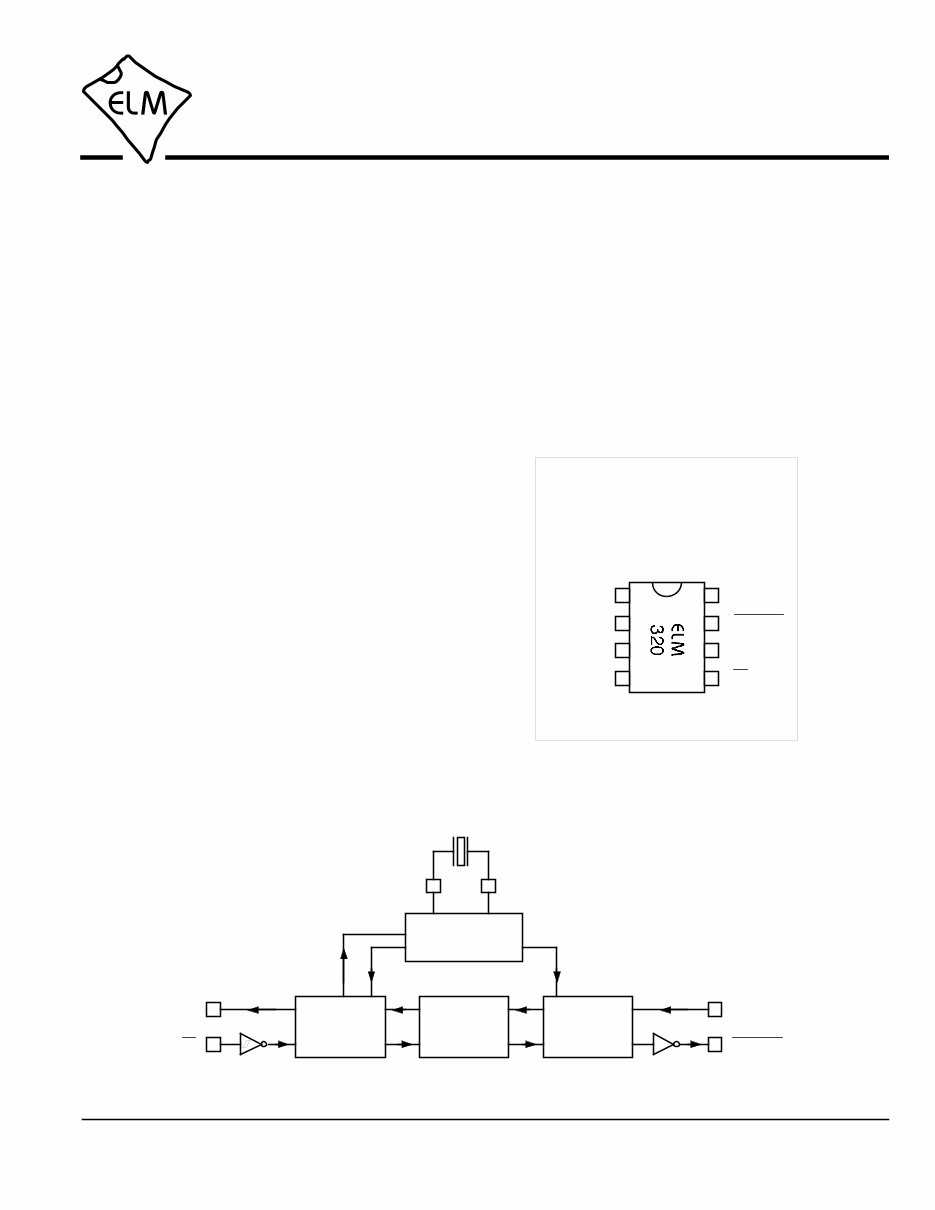
Connection Diagram
PDIP and SOIC
(top view)
VDD VSS
Since the 1996 model year, North American
automobiles have been required to provide an OBD,
or On Board Diagnostics, port for the connection of
test equipment. Data is transferred serially between
the vehicle and the external equipment using this
connection, in a manner specified by the Society of
Automotive Engineers (SAE) standards. In addition
to operating at different voltage levels, these ports
also use a data format that is not compatible with the
standard used for personal computers.
The ELM320 is an 8 pin integrated circuit that is
able to change the data rate and reformat the OBD
signals into easily recognized ASCII characters. This
allows virtually any personal computer to
communicate with an OBD equipped vehicle using
only a standard serial port and a terminal program.
By also enhancing it with an interface program,
hobbyists can create their own custom scan tool.
This integrated circuit was designed to provide a
cost-effective way for experimenters to work with an
OBD system, so a few features such as RS232
handshaking, variable baud rates, etc., have not
been implemented. In addition, this device is only
able to communicate using the 41.6KHz J1850 PWM
protocol that is commonly used in Ford Motor
Company vehicles.
• Low power CMOS design
• High current drive outputs
• Crystal controlled for accuracy
• Fully configurable using AT commands
• Standard ASCII character output
• High speed RS232 communications
• 41.6KHz J1850 PWM protocol
• Diagnostic trouble code readers
• Automotive scan tools
OBDOut
Tx
Description
Applications
Block Diagram
Features
OBDIn Rx
1
2
3
8
7
6
5 4
XT1
XT2
Tx
RS232
Interface
3.58MHz
2 3
XT1 XT2
Rx
5
6
Timing and
Control
Interpreter
OBD
Interface
OBDOut
4
7
OBDIn
Elm Electronics – Circuits for the Hobbyist
< http://www.elmelectronics.com/ >
OBD (PWM) to RS232 Interpreter
1 of 16 ELM320DSD
ELM320

Elm Electronics – Circuits for the Hobbyist
< http://www.elmelectronics.com/ >
Pin Descriptions
Ordering Information
These integrated circuits are available in either the 300 mil plastic DIP format, or in the 208 mil SOIC surface
mount type of package. To order, add the appropriate suffix to the part number:
300 mil Plastic DIP............................... ELM320P 208 mil SOIC..................................... ELM320SM
2 of 16
All rights reserved. Copyright 2001 to 2009 by Elm Electronics Inc.
Every effort is made to verify the accuracy of information provided in this document, but no representation or warranty can be
given and no liability assumed by Elm Electronics with respect to the accuracy and/or use of any products or information
described in this document. Elm Electronics will not be responsible for any patent infringements arising from the use of these
products or information, and does not authorize or warrant the use of any Elm Electronics product in life support devices and/or
systems. Elm Electronics reserves the right to make changes to the device(s) described in this document in order to improve
reliability, function, or design.
VDD (pin 1)
This pin is the positive supply pin, and should
always be the most positive point in the circuit.
Internal circuitry connected to this pin is used to
provide power on reset of the microprocessor, so
an external reset signal is not required. Refer to
the Electrical Characteristics section for further
information.
XT1 (pin 2) and XT2 (pin 3)
A 3.579545 MHz NTSC television colourburst
crystal is connected between these two pins.
Crystal loading capacitors (typically 27pF) will
also normally be connected between each of the
pins and the circuit common (Vss).
OBDIn (pin 4)
The OBD data is input to this pin, with a high
logic level representing the active state (and a
low, the passive). No Schmitt trigger input is
provided, so the OBD signal should be buffered
to minimize transition times for the internal
CMOS circuitry. The external level shifting
circuitry is usually sufficient to accomplish this –
see the Example Application section for a typical
circuit.
Rx (pin 5)
The computer’s RS232 transmit signal can be
directly connected to this pin from the RS232
line, as long as a current limiting resistor
(typically about 47KΩ) is installed in series.
(Internal protection diodes will pass the input
currents safely to the supply connections,
protecting the ELM320.) Internal signal inversion
and Schmitt trigger waveshaping provide the
necessary signal conditioning.
Tx (pin 6)
The RS232 data output pin. The signal level is
compatible with most interface ICs, and there is
sufficient current drive to allow interfacing using
only a single PNP transistor, if desired.
OBDOut (pin 7)
This is the active low output signal which is used
to drive the OBD bus to the active state. Since
the J1850 PWM standard requires a differential
bus signal, the user must create the complement
of this signal to drive the other bus line. See the
Example Application section for more details.
VSS (pin 8)
Circuit common is connected to this pin. This is
the most negative point in the circuit.
ELM320DSD
ELM320

Elm Electronics – Circuits for the Hobbyist
< http://www.elmelectronics.com/ >
Electrical Characteristics
Absolute Maximum Ratings
Storage Temperature....................... -65°C to +150°C
Ambient Temperature with
Power Applied.................................... -40°C to +85°C
Voltage on VDD with respect to VSS............ 0 to +7.5V
Voltage on any other pin with
respect to VSS........................... -0.6V to (VDD + 0.6V)
Note:
Stresses beyond those listed here will likely damage
the device. These values are given as a design
guideline only. The ability to operate to these levels
is neither inferred nor recommended.
3 of 16
All values are for operation at 25°C and a 5V supply, unless otherwise noted. For further information, refer to note 1 below.
Characteristic Minimum Typical Maximum Conditions Units
Supply voltage, VDD 4.5 5.0 5.5 V
VDD rate of rise 0.05 V/ms
Average supply current, IDD 1.0 2.4 mA
Notes:
1. This integrated circuit is produced with a Microchip Technology Inc.’s PIC12C509A as the core embedded
microcontroller. For further device specifications, and possibly clarification of those given, please refer to the
appropriate Microchip documentation (available at http://www.microchip.com/).
2. This spec must be met in order to ensure that a correct power on reset occurs. It is quite easily achieved
using most common types of supplies, but may be violated if one uses a slowly varying supply voltage, as
may be obtained through direct connection to solar cells, or some charge pump circuits.
3. Device only. Does not include any load currents.
4. This specification represents the current flowing through the protection diodes when applying large voltages
to the Rx input (pin 5) through a current limiting resistance. Currents quoted are the maximum that should be
allowed to flow continuously.
5. Nominal data transfer rate when a 3.58 MHz crystal is used as the frequency reference. Data is transferred
to and from the ELM320 with 8 data bits, no parity, and 1 stop bit (8 N 1).
Input low voltage VSS 0.15 VDD V
Input high voltage VDD V 0.85 VDD
Output low voltage 0.6 V
Output high voltage V VDD - 0.7
Current (sink) = 8.7mA
Current (source) = 5.4mA
see note 2
ELM320DSD
see note 3
Rx pin input current mA see note 4 -0.5
RS232 baud rate baud see note 5 9600
+0.5
ELM320

4 of 16 ELM320DSD Elm Electronics – Circuits for the Hobbyist
< http://www.elmelectronics.com/ >
Overview
The ELM320 relies on a standard RS232 type
serial connection to communicate with the user. The
data rate is fixed at 9600 baud, with 8 data bits, no
parity bit, 1 stop bit, and no handshaking (often
referred to as 9600 8N1). All responses from the IC
are terminated with a single carriage return character
and, by default, a line feed character as well. Make
sure your software is configured properly for the mode
you have chosen.
Properly connected and powered, the ELM320 will
initially display the message:
ELM320 v2.0
>
In addition to identifying the version of the IC,
receipt of this string is a convenient way to be sure
that the computer connections and the settings are
correct. However, at this point no communications
have taken place with the vehicle, so the state of that
connection is still unknown.
The ‘>’ character displayed above is the ELM320’s
prompt character. It indicates that the device is in its
idle state, ready to receive characters on the RS232
port. Characters sent from the computer can either be
intended for the ELM320’s internal use, or for
reformatting and passing on to the vehicle’s OBD bus.
Commands for the ELM320 are distinguished from
those to the vehicle by always beginning with the
characters ‘AT’ (as is common with modems), while
commands for the OBD bus must contain only the
ASCII characters for hexadecimal digits (0 to 9 and A
to F). This allows the ELM320 to quickly determine
where the received characters are to be directed.
Whether an ‘AT’ type internal command or a hex
string for the OBD bus, all messages to the ELM320
must be terminated with a carriage return character
(hex ‘0D’) before it will be acted upon. The one
exception is when an incomplete string is sent and no
carriage return appears. In this case, an internal timer
will automatically abort the incomplete message after
about 10 seconds, and the ELM320 will print a single
question mark to show that the input was not
understood (and was ignored).
Messages that are misunderstood by the ELM320
(syntax errors) will always be signalled by a single
question mark (‘?’). These include incomplete
messages, invalid hexadecimal digit strings, or
incorrect AT commands. It is not an indication of
whether or not the message was understood by the
vehicle. (The ELM320 is a protocol interpreter that
makes no attempt to assess OBD messages for
validity – it only ensures that an even number of hex
digits were received, combined into bytes, and sent
out the OBD port, so it cannot determine if the
message sent to the vehicle is in error.)
Incomplete or misunderstood messages can also
occur if the controlling computer attempts to write to
the ELM320 before it is ready to accept the next
command (as there are no handshaking signals to
control the data flow). To avoid a data overrun, users
should always wait for the prompt character (‘>’)
before issuing the next command.
Finally, a few convenience items to note. The
ELM320 is not case-sensitive, so ‘ATZ’ is equivalent to
‘atz’, and to ‘AtZ’. The device ignores space characters
as well as control characters (tab, linefeed, etc.) in the
input, so they can be inserted anywhere to improve
readability and, finally, issuing only a single carriage
return character will repeat the last command (making
it easier to request updates on dynamic data such as
engine rpm).
Communicating with the ELM320
The following describes how to use the ELM320 to
obtain a great deal of information from your vehicle. To
many, the quantity of information will be overwhelming,
and to others it is not nearly enough.
We begin by discussing just how to talk to the IC,
then how to adjust some options through the use of
‘AT’ commands, and finally go on to actually talk to the
vehicle, obtaining trouble codes and resetting them.
For the more advanced experimenters, there are also
sections on how to use some of the programmable
features of this product as well.
It is not as daunting as it first appears. Many users
will never need to issue an ‘AT’ command, adjust
timeouts or change the headers. For most, all that is
required is a PC or a PDA with a terminal program
(such as HyperTerminal or ZTerm), and knowledge of
one or two OBD commands, which we provide in the
following…
ELM320

5 of 16 ELM320DSD Elm Electronics – Circuits for the Hobbyist
< http://www.elmelectronics.com/ >
AT Commands
Several parameters within the ELM320 can be
adjusted in order to modify its behaviour. These do not
normally have to be changed before attempting to talk
to the vehicle, but occasionally the user may wish to
customize the settings, for example by turning the
character echo off, adjusting the timeout value, or
changing the header addresses. In order to do this,
internal ‘AT’ commands must be issued.
Those familiar with PC modems will immediately
recognize AT commands as a standard way in which
modems are internally configured. The ELM320 uses
essentially the same method, always watching the
data sent by the PC, looking for messages that begin
with the character ‘A’ followed by the character ‘T’. If
found, the next characters will be interpreted as
internal configuration or ‘AT’ commands, and will be
executed upon receipt of a terminating carriage return
character. The ELM320 will reply with the characters
‘OK’ on the successful completion of a command, so
the user knows that it has been executed.
Some of the following commands allow passing
numbers as arguments in order to set the internal
values. These will always be hexadecimal numbers
which must be provided in pairs. The hexadecimal
conversion chart in the next section may prove useful
if you wish to interpret the values. Also, one should be
aware that for the on/off types of commands, the
second character is a number (1 or 0), the universal
terms for on and off, respectively.
The following is a summary of all of the AT
commands that are recognized by the current version
of the ELM320, sorted alphabetically. Users of
previous versions of this product (v1.x) should note
that their ICs will only support the E, H and Z options.
AR [ A utomatically set the R eceive address ]
Responses from the vehicle will be acknowledged
and displayed by the ELM320, if its internally stored
receive address matches the address that the
message is being sent to. With the auto receive
mode in effect, the value used for the receive
address will be chosen based on the current header
bytes, and will automatically be updated whenever
the header bytes are changed.
The value that is used for the receive address is
determined based on the contents of the first header
byte. If it shows that the message uses physical
addressing, the third header byte of the header is
used for the receive address, otherwise (for
functional addressing) the second header byte,
increased in value by 1, will be used. Auto Receive
is turned on by default.
D [ set all to D efaults ]
This command is used to set the E, H, L, and R
options to their default (or factory) settings, as when
power is first applied. Additionally, the Auto Receive
mode (AR) will be selected, data will be transmitted
in the standard formatted way (as if chosen by FD),
the ‘NO DATA’ timeout will be set to its default value,
and the header bytes will be set to the proper values
for the OBDII operation.
E0 and E1 [ E cho off (0) or on(1) ]
These commands control whether or not characters
received on the RS232 port are retransmitted (or
echoed) back to the host computer. To reduce traffic
on the RS232 bus, users may wish to turn echoing
off by issuing ATE0. The default is E1 (echo on).
FD [ send F ormatted D ata ]
This command requests that all responses be
returned as standard ASCII characters which are
readable on virtually any standard terminal program.
Hex digits are shown as two ASCII characters, and
spaces are provided between each byte as a
separator. Also, every line will end with a carriage
return character and (optionally) a linefeed
character, ensuring that every response appears on
a new line. This is the default mode.
H0 and H1 [ H eaders off (0) or on(1) ]
These commands control whether or not the header
information is shown in the responses. All OBD
messages have an initial (header) string of three
bytes and a trailing check digit which are normally
not displayed by the ELM320. To see this extra
information, users can turn the headers on by
issuing an ATH1. The default is H0 (headers off).
ELM320

6 of 16 ELM320DSD Elm Electronics – Circuits for the Hobbyist
< http://www.elmelectronics.com/ >
AT Commands (continued)
I [ I dentify yourself ]
Issuing this command causes the chip to identify
itself, by printing the startup product ID string (this is
currently ‘ELM320 v2.0’). Software can use this to
determine exactly which integrated circuit it is talking
to, without resorting to resetting the entire IC.
L0 and L1 [ L inefeeds off (0) or on(1) ]
Whether the ELM320 transmits a linefeed character
after each carriage return character is controlled by
this option. If an ATL1 is issued, linefeed generation
will be turned on, and for ATL0, it will be off. Users
may wish to have this option on if using a terminal
program, but off if using a custom interface (as the
extra characters transmitted will only serve to slow
the vehicle polling down). The default setting is L1
(linefeeds on)
MA [ M onitor A ll messages ]
Using this command places the ELM320 into a bus
monitoring mode, in which it displays all messages
as it sees them on the OBD bus. This continues
indefinitely until stopped by activity on the RS232
input. To stop the monitoring, one should send any
single character then wait for the ELM320 to respond
with a prompt character (‘>’). Waiting for the prompt
is necessary as the response time is unpredictable,
varying depending on the IC was doing when
interrupted. If for instance it is in the middle of
printing a line, it will first complete the line then
return to the command state, issuing the prompt
character. If it were simply waiting for input, it would
return immediately. The character which stops the
monitoring will always be discarded, and will not
affect subsequent commands.
MR hh [ M onitor for R eceiver hh ]
This command also places the IC in a bus monitoring
mode, displaying only messages that were sent to
the hex address given by hh (i.e. messages which
are found to have that value in their second byte).
Any RS232 activity (single character) aborts the
monitoring, as with the MA command.
MT hh [ M onitor for T ransmitter hh ]
Another monitoring command, which displays only
messages sent by Transmitter address hh. As with
the MA and MR monitoring modes, any RS232
activity (single character) aborts the monitoring.
PD [ send P acked D ata ]
This option is for those that are building a computer
interface and want the fastest data transfer rate
possible while still operating at 9600 baud. When
selected, responses from the vehicle will be
formatted as an initial length byte followed by the
actual response bytes from the vehicle, with no
trailing carriage returns or linefeed characters. The
data will not be altered in any way, except for the
conversion to standard RS232 bytes.
Note that the length byte only represents the total
number of data bytes following, and does not include
itself. Also, if there was a data (checksum) error, the
length byte will have its most significant bit set, so
the user should always check first to see if the length
is greater than 127. (The other 7 bits still provide a
valid byte count if there is an error, so one need only
ignore the msb, or subtract 128 from the value.)
A ‘NO DATA’ response has no data bytes, but still
sends a length byte with value ‘0’.
R0 and R1 [ R esponses off (0) or on(1) ]
These commands control the ELM320’s automatic
display of responses. If responses have been turned
off, the IC will not wait for anything to be returned
from the vehicle after sending a request, and will
return immediately to waiting for RS232 commands.
This is useful if sending commands blindly when
using the IC for a non-OBD network application, or
simulating an ECU, in a basic learning environment.
It is not recommended that this option normally be
used, however, as the vehicle may have difficulty if it
is expecting an acknowledgement byte and never
receives one. The default is R1 (responses on).
SH xx yy zz [ S et the H eader to xx yy zz ]
This command allows the user to control the values
that are sent as the three header bytes in the
message. The value of hex digits xx will be used for
the first or priority/type byte, yy will be used for the
second or target byte, and zz will be used for the
third or source byte. These remain in effect until set
again, or until restored to the default values with the
AT D, or AT Z commands. The default header values
ELM320

7 of 16 ELM320DSD Elm Electronics – Circuits for the Hobbyist
< http://www.elmelectronics.com/ >
AT Commands (continued)
ELM320 AT Commands
general
responses
requests
set all to Defaults D
show the ID string I
reset all Z
repeat last command <CR>
Echo on/off E1/0
Headers on/off H1/0
Linefeeds on/off L1/0
Responses on/off R1/0
ST hh Set Timeout (hh*4ms)
SH xx yy zz Set Header
SR hh Set Rx address
AR Auto Receive
MA Monitor All
MR hh Monitor for Rxer hh
use Packed Data PD
use Formatted Data FD
MT hh Monitor for Txer hh
are 61 6A F1, as required by the SAE J1979
Diagnostic Test Modes (OBDII) standard.
SR hh [S et the R eceive address to hh ]
Depending on the application, users may wish to
manually set the address to which the ELM320 will
respond. Issuing this command will turn off the AR
mode, and force the IC to only accept responses
addressed to hh. Use caution with this setting, as
depending on what you set it to, you may end up
accepting (acknowledging with an IFR) a message
that was actually meant for another module.
ST hh [ S et T imeout to hh ]
After sending a request, the ELM320 waits a preset
time before declaring that there was no response
from the vehicle (the ‘NO DATA’ response).
Depending on the application (and priority of the
request), users may want modify this timeout period
before declaring the request a failure. The ST
command is used to do that.
The actual time used is (approximately) 4 ms x the
byte value passed as the hexadecimal argument.
Passing a value of FF thus results in a maximum
time of about 1020 ms. Values less than 08 will be
ignored and forced to a value of 8, providing a
minimum time of 32ms. The default value is 32
(decimal 50) providing a timeout of 200 ms.
Z [ reset all ]
This command causes the chip to perform a
complete reset as if power were cycled off and then
on again. All settings are returned to their default
values, and the chip will be put in the idle state,
waiting for characters on the RS232 bus.
AT Command Summary
Figure 1 (at the right) shows all of the ELM320
commands in one convenient chart. In order to help
with the understanding of these, we have grouped
the commands into three functional areas, but this
has no bearing on how the commands are to be
used, it is only for clarity. You may find this chart to
be useful when experimenting with the IC.
Figure 1. ELM320 AT Commands
ELM320

If the bytes received on the RS232 bus do not
begin with the letters A and T, they are assumed to be
commands for the vehicle’s OBD bus. The bytes will
be tested to ensure that they are valid pairs of
hexadecimal digits and, if they are, will be combined
into bytes for transmitting to the vehicle. Recall that no
checks are made as to the validity of the OBD
command – data is simply retransmitted as received.
OBD commands are actually sent to the vehicle
embedded in a data message. The standards require
that every message begin with three header bytes and
end with a checksum byte, which the ELM320 adds
automatically to every message. The ELM320 powers-
on expecting to be used for the OBDII mandated
emissions diagnostics, and sets the header bytes
accordingly. If you wish to perform more advanced
functions, these bytes may be changed through the
use of AT commands. To view the extra bytes that are
received with the vehicle’s messages, turn the header
display on by issuing an ATH1 command.
The command portion of most OBD messages is
usually only one or two bytes in length, but can
occasionally be longer as the standard allows for as
many as seven. The current version of the ELM320
will accept the maximum seven command bytes (or 14
hexadecimal digits) per message, while users of
previous versions (v1.x) were limited to only three
command bytes. In either case, attempts to send more
than the maximum number of bytes allowed will result
in a syntax error, with the entire command being
ignored and a single question mark printed.
The use of hexadecimal digits for all of the data
exchange was chosen as it is the most common data
format used in the relevant SAE standards. It is
consistent with mode request listings and is the most
frequently used format for displaying results. With a
little practice, it should not be very difficult to deal in
hex numbers, but some may initially find the table in
Figure 2 or a calculator to be invaluable. All users will
eventually be required to manipulate the results in
some way, though (combine bytes and divide by 4 to
obtain rpm, divide by 2 to obtain degrees of advance,
etc.), and may find a software front-end more helpful.
As an example of sending a command to the
vehicle, assume that A6 (or decimal 166) is the
command that is required to be sent. In this case, the
user would type the letter A, then the number 6, then
would press the return key. These three characters
would be sent to the ELM320 on the RS232 bus. The
ELM320 would store the characters as they are
received, and when the third character (the carriage
return) is received, begin to assess the other two. It
would see that they are both valid hex digits, and
would convert them to a one byte value (with a
decimal value of 166). Three header bytes and a
checksum byte would be added, so a total of five bytes
would be sent to the vehicle. Note that the carriage
return character is only a signal to the ELM320, and is
not sent on to the vehicle.
After sending a command, the ELM320 listens on
the OBD bus for any responses that are directed to it.
Each received byte is converted to the equivalent
hexadecimal pair of ASCII characters and transmitted
on the RS232 port for the user. Rather than send
control characters which are unprintable on most
terminals, the digits are sent as numbers and letters
(e.g. the hex digit ‘A’ is transmitted as decimal value
65, and not 10).
If there was no response from the vehicle, due to
no data being available, or because the command is
not supported, a ‘NO DATA’ message will be sent. See
the error messages section for a description of this
message and others.
8 of 16 ELM320DSD Elm Electronics – Circuits for the Hobbyist
< http://www.elmelectronics.com/ >
OBD Commands
Figure 2. Hex to Decimal Conversion
Hexadecimal
Number
Decimal
Equivalent
0
1
3
2
4
5
6
0
1
3
2
4
5
6
7 7
8 8
9 9
A 10
B 11
C 12
D 13
E 14
F 15
ELM320

9 of 16 ELM320DSD Elm Electronics – Circuits for the Hobbyist
< http://www.elmelectronics.com/ >
Talking to the Vehicle
The ELM320 cannot be directly connected to a
vehicle as it is, but needs support circuitry as shown in
the Example Applications section. Once incorporated
into such a circuit, you only need to use a terminal
program to send bytes to, and receive them from, the
vehicle.
SAE standards specify that command bytes sent
to the vehicle must adhere to a set format. The first
byte (known as the ‘mode’) always describes the type
of data being requested, while the second, third, etc.
bytes specify the actual information required (given by
a ‘parameter identification’ or PID number). The
modes and PIDs are described in detail in the SAE
standard documents J1979 and J2190, and may also
be expanded on by the vehicle manufacturers.
Normally, one is only concerned with the nine
diagnostic test modes described in J1979 (although
there is provision for more). Note that it is not a
requirement for all of them to be supported. These are
the nine modes:
01 : show current data
02 : show freeze frame data
03 : show diagnostic trouble codes
04 : clear trouble codes and stored values
05 : test results, oxygen sensors
06 : test results, non-continuously monitored
07 : test results, continuously monitored
08 : special control mode
09 : request vehicle information
Within each mode, PID 00 is normally reserved to
show which PIDs are supported by that mode. Mode
01, PID 00 is required to be supported by all vehicles,
and can be accessed as follows…
Ensure that the ELM320 is properly connected to
your vehicle, and powered. Most vehicles will not
respond without the ignition key in the ON position, so
turn the ignition on, but do not start the vehicle. At the
prompt, issue the mode 01 PID 00 command:
>01 00
A typical response could be as follows:
41 00 BE 1F B8 10
The 41 00 signifies a response (4) from a mode 1
request with PID 00 (a mode 2, PID 00 request is
answered with a 42 00, etc.). The next four bytes (BE,
1F, B8, and 10) represent the requested data, in this
case a bit pattern showing which of PIDs 1 through 32
are supported by this mode (1=supported, 0=not).
Although this information is not very useful for the
casual user, it does serve to show that you are
communicating with the vehicle.
Another example requests the current engine
coolant temperature (ECT). This is PID 05 in mode 01,
and is requested as follows:
>01 05
The response will be of the form:
41 05 7B
This shows a mode 1 response (41) from PID 05,
with value 7B. Converting the hexidecimal 7B to
decimal, one gets 7 x 16 + 11 = 123. This represents
the current temperature in degrees Celsius, with the
zero value offset by 40 degrees to allow operation at
subzero temperatures. To convert to the actual coolant
temperature, simply subtract 40 from the value. In this
case, then, the ECT is 123 - 40 = 83 degrees Celsius.
A final example shows a request for the OBD
requirements to which this vehicle was designed. This
is PID 1C of mode 01, so at the prompt, type:
>01 1C
A typical response would be:
41 1C 01
The returned value (01) shows that this vehicle
conforms to OBDII (California ARB) standards. The
presently defined responses are :
01 : OBDII (California ARB)
02 : OBD (Federal EPA)
03 : OBD and OBDII
04 : OBD I
05 : not intended to meet any OBD requirements
06 : EOBD (Europe)
Some modes may provide multi-line responses
(09, if supported, can display the vehicle’s serial
number). The ELM320 will attempt to display all
responses in these cases, but only if it is allowed
sufficient time to process each. There may be
occasions when the vehicle responds too quickly to
allow time for reprocessing, and lines could be lost.
Hopefully this has shown how typical requests
proceed. It has not been meant to be a definitive
source on modes and PIDs – this information can be
obtained from the manufacturer of your vehicle, from
the SAE (www.sae.org), ISO (www.iso.org), or from
various other sources on the web.
ELM320

Interpreting Trouble Codes
10 of 16 ELM320DSD Elm Electronics – Circuits for the Hobbyist
< http://www.elmelectronics.com/ >
Likely the most common use that the ELM320 will
be put to is in obtaining the current Diagnostic Trouble
Codes or DTCs. Minimally, this requires that a mode
03 request be made, but first one should determine
how many trouble codes are presently stored. This is
done with a mode 01 PID 01 request as follows:
>01 01
To which a typical response might be:
41 01 81 07 65 04
The 41 01 signifies a response to our request, and
the first data byte (81) is the result that we are looking
for. Clearly there would not be 81(hex) or 129(decimal)
trouble codes if the vehicle is operational. In fact, this
byte does double duty, with the most significant bit
being used to indicate that the malfunction indicator
lamp (MIL, or ‘Check Engine’) has been turned on by
one of this module’s codes (if there are more than
one), while the other 7 bits provide the actual number
of stored codes. To determine the number of stored
codes, then, one needs to subtract 128 (or 80 hex)
from the number if it is greater than 128, and otherwise
simply read the number of stored codes directly.
The above response then indicates that there is
one stored code, and it was the one that set the MIL or
‘Check Engine’ lamp on. The remaining bytes in the
response provide information on the types of tests
supported by that particular module (see SAE
document J1979 for further information).
In this instance, there was only one line to the
response, but if there were codes stored in other
modules, they each could have provided a line of
response. To determine which module is reporting the
trouble code, one would have to turn the headers on
(ATH1) and then look at the third byte of the three byte
header for the address of the module that sent the
information.
Having determined the number of codes stored,
the next step is to request the actual trouble codes
with a mode 03 request:
>03
A response to this could be:
43 01 33 00 00 00 00
The ‘43’ in the above response simply indicates
that this is a response to a mode 03 request. The other
6 bytes in the response have to be read in pairs to
show the trouble codes (the above would be
interpreted as 0133, 0000, and 0000). Note that there
is only one trouble code here. The response has been
padded with 00’s as is required by the standard, and
the extra 0000’s do not represent actual trouble codes.
As was the case when requesting the number of
stored codes, the most significant bits of each trouble
code also contain additional information. It is easiest to
use the following table to interpret the first digit of
trouble codes as follows:
Powertrain Codes - SAE defined
0
“ “ - manufacturer defined
“ “ - SAE defined
“ “ - jointly defined
1
2
3
If the first hex digit received is this,
Replace it with these two characters
Chassis Codes - SAE defined
4
“ “ - reserved for future
5
6
7
Body Codes - SAE defined
8
9
A
B
Network Codes - SAE defined
C
D
E
F
P0
P1
P2
P3
C0
C1
C2
C3
B0
B1
B2
B3
U0
U1
U2
U3
“ “ - reserved for future
“ “ - manufacturer defined
“ “ - manufacturer defined
“ “ - manufacturer defined
“ “ - manufacturer defined
“ “ - manufacturer defined
“ “ - manufacturer defined
“ “ - reserved for future
Taking the example trouble code (0133), the first
digit (0) would then be replaced with P0, and the 0133
reported would become P0133 (which is the code for
an ‘oxygen sensor circuit slow response’). As for
further examples, if the response had been D016, the
code would be interpreted as U1016, while 1131 would
be P1131.
Had there been codes stored by more than one
module, or more than three codes stored in the same
module, the above response would have consisted of
multiple lines. To determine which module is reporting
each trouble would then require turning the headers on
with an ATH1 command.
ELM320
You're Reading a Preview
What's Included?
Fast Download Speeds
Online & Offline Access
Access PDF Contents & Bookmarks
Full Search Facility
Print one or all pages of your manual
$31.99
Viewed 81 Times Today


Secure transaction
What's Included?
Fast Download Speeds
Online & Offline Access
Access PDF Contents & Bookmarks
Full Search Facility
Print one or all pages of your manual
$31.99
If you're looking to create your own cable for the FORD ELM320 OBD PWM to RS323 interpreter, you'll need to follow these steps:
- First, gather the necessary materials, including an OBD-II connector, RS232 connector, and appropriate cables.
- Next, refer to the pinout diagram for the ELM320 and identify the corresponding pins for the OBD-II and RS232 connectors.
- Then, carefully solder the cables to the respective pins on the connectors, ensuring proper connections.
- After the soldering is complete, insulate the connections with heat shrink tubing to prevent any short circuits.
- Finally, test the cable to ensure it is functioning correctly with the FORD ELM320 OBD PWM to RS323 interpreter.
Creating your own cable can be a cost-effective solution for connecting the FORD ELM320 OBD PWM to RS323 interpreter, and it's a useful skill for both professional mechanics and DIY enthusiasts.


