A/C COMPRESSOR OIL CHECKING A/C General Servicing COMPRESSOR OIL CHECKING REFRIGERANT OIL Only new, pure, moisture-free refrigerant oil should be used in the air conditioning system. This oil is highly refined and dehydrated to a point where moisture content is less than 10 parts per million. The oil container must be tightly closed at all times when not in use, or moisture will be absorbed from the air and introduced into the refrigeration system. DISCHARGING SYSTEM If compressor has stem-type service valves, it can be isolated and removed without discharging entire system. Otherwise, discharge system completely using approved refrigerant recovery/recycling equipment before loosening any fittings. DISCONNECTING LINES & FITTINGS After system is discharged, carefully clean area around all fittings to be opened. Always use 2 wrenches when tightening or loosening fittings to avoid twisting or distorting lines. Cap or plug all openings as soon as lines are removed. Do not remove caps until immediately before connections are made. This will keep entry of air and moisture to a minimum, reducing the chance of damage to components. PLACING SYSTEM IN OPERATION After component service or replacement has been completed and all connections have been made, evacuate system thoroughly with a vacuum pump. Charge system with proper amount of refrigerant and perform a leak test. Be sure to check all fittings that have been opened. After system has been leak tested, make a system performance check. FORD & NIPPONDENSO 6-CYLINDER MODELS FS-6, 6E-171 & 6P-148 6-CYLS. When inspecting the system to determine oil loss, check for signs of leaking (a wet, shiny looking spot on system components). If a component is removed after the system has been operated, some oil will remain in the component. If oil leak is noted or components replacement is required, oil will have to be restored to original level, as follows: DURING COMPRESSOR REPLACEMENT CAUTION: When discharging air conditioning system, use only approved refrigerant recovery/recycling equipment. Make every attempt to avoid discharging refrigerant into the atmosphere.
Discharge system using approved refrigerant recovery/recycling equipment and replace components as necessary. A new compressor contains 10 ounces of new refrigeration oil. Prior to installing new compressor, drain 4 ounces of the oil from new compressor. This will maintain total system charge of 10 ounces. DURING COMPONENT REPLACEMENT When replacing components other than the compressor, oil must be added to new component to maintain system charge at 10 ounces. If evaporator is replaced, add 3 ounces; if the condenser is replaced, add 1 ounce. If accumulator is to be replaced, remove accumulator. Drain oil from old accumulator and measure amount removed. Before installing new accumulator, add the same amount of oil plus 1 ounce. COMPRESSOR FAILURE & SYSTEM CONTAMINATED If either of these situations exists, discharge system using approved refrigerant recovery/recycling equipment and remove compressor, accumulator and orifice tube. Inspect orifice tube for contaminants. Clean and replace as necessary. Flush entire system. Install a new compressor (if necessary) and a new accumulator. New compressors are charged with proper amount of oil, 10 ounces. If reinstalling old compressor, add 10 ounces of new refrigeration oil through suction port. Evacuate and charge system. NIPPONDENSO 10-CYLINDER MODELS 10P15, 10P15C & 10PA20 10-CYLS. To ensure that the Nippondenso 10-cylinder compressor has the proper amount of lubricating oil, discharge the system using approved refrigerant recovery/recycling equipment and remove the compressor. Remove the service valve assembly. Turn the compressor upside down and drain the oil from it. Once the oil has been drained, refill the compressor with 2.0-3.4 oz. of Denso oil 6, Suniso No. 5GS or equivalent compressor oil. TECUMSEH HR 980, 4-CYLINDER The Tecumseh 4-cylinder compressor system requires a refrigeration oil charge of 8 ounces. If a component is removed from the system, some oil is lost with that component. The procedures for replacing oil are as follows: DURING COMPRESSOR REPLACEMENT A new compressor comes charged with 8 ounces of refrigeration oil. Before installing the compressor, drain out 4 ounces from the new compressor. This will maintain the system total charge within the 8 ounce limit. DURING COMPONENT REPLACEMENT When replacing the evaporator, add 3 ounces; for the condenser, add 1 ounce. If an accumulator is replaced, drain oil from accumulator through the pressure sensing switch fitting (Schrader valve removed). Measure the amount of oil removed, and add that amount plus 1 ounce to the new accumulator. No oil needs to be added to compensate for loss when valves or hoses are replaced.
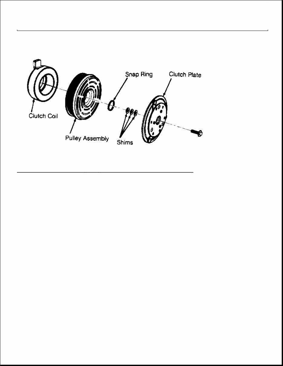
A/C COMPRESSOR OVERHAUL - 10-CYL A/C GENERAL SERVICING Nippondenso/Ford 10-Cylinder Compressor Overhaul DESCRIPTION The Nippondenso/Ford 10-cyl. compressor is a reciprocating piston type. The pistons are operated by a swashplate which moves the pistons back and forth in the cylinders as the shaft is rotated. There are 10 separate cylinders, 5 at the rear of the compressor and 5 at the front. Reed valves are provided for each cylinder. CLUTCH ASSEMBLY R & I FORD FX-15 10-CYLINDER 1. Using Spanner (T70P-4067-A), remove clutch plate retaining bolt and discard. Using an 8 mm bolt threaded into clutch plate, remove clutch plate. Remove clutch plate shims. 2. Remove snap ring and remove pulley assembly. Remove snap ring. Disconnect electrical wiring and remove clutch coil. To install, reverse removal procedure. Install pulley assembly snap ring with beveled side out. 3. Install new clutch plate retaining bolt and tighten to 96-120 INCH lbs. (11-14 N.m). Using a feeler gauge, rotate clutch assembly and check clearance in 3 places. Proper clearance is .018-.038" (.46-.97 mm). If clearance is not correct, add or remove shims. NOTE: This article covers shaft seal, pulley bearing and clutch coil replacement procedures for Ford & Nippondenso 10-cyl. compressors. The shaft seal assembly is precision-machined with its critical parts finished to extremely close tolerance and as such must be handled with great care. Its slip face demands particularly careful handling.
Fig. 1: Exploded View of FX - 15 10 - Cylinder Compressor Clutch Assembly NIPPONDENSO 10P15, 10P15F Removal 1. Using Spanner (T81P-19623-MH), hold clutch plate and remove crankshaft nut. Using Clutch Plate Remover (T80L-19703-B), pull clutch plate from compressor. Remove clutch plate shims. 2. Remove snap ring and clutch pulley assembly. If pulley assembly cannot be removed by hand, use Shaft Protector (T80L-19703-G) and 3-jaw puller. Remove snap ring. Disconnect electrical wiring and remove clutch coil. Installation 1. Install clutch coil over locating pin and install snap ring. Connect electrical wiring. 2. Install pulley assembly, using Pulley Installer (T80L-19703-J) and hammer (if necessary). Install snap ring with beveled side outward. Install clutch plate shims. 3. Ensure clutch plate aligns with crankshaft key. Using Clutch Plate Installer (T80L-19703-F), install clutch plate. Install crankshaft nut. Using spanner, tighten nut to 10-14 ft. lbs. (13-20 N.m). DO NOT tighten nut with air tools. 4. Using feeler gauge, check clearance between clutch plate and pulley. Rotate compressor clutch and check clearance in more than one place. Proper clearance is .021-.036" (.53-.91 mm). If clearance is not correct, add or remove shims. NOTE: Remove compressor when clearance is not adequate for clutch assembly removal.
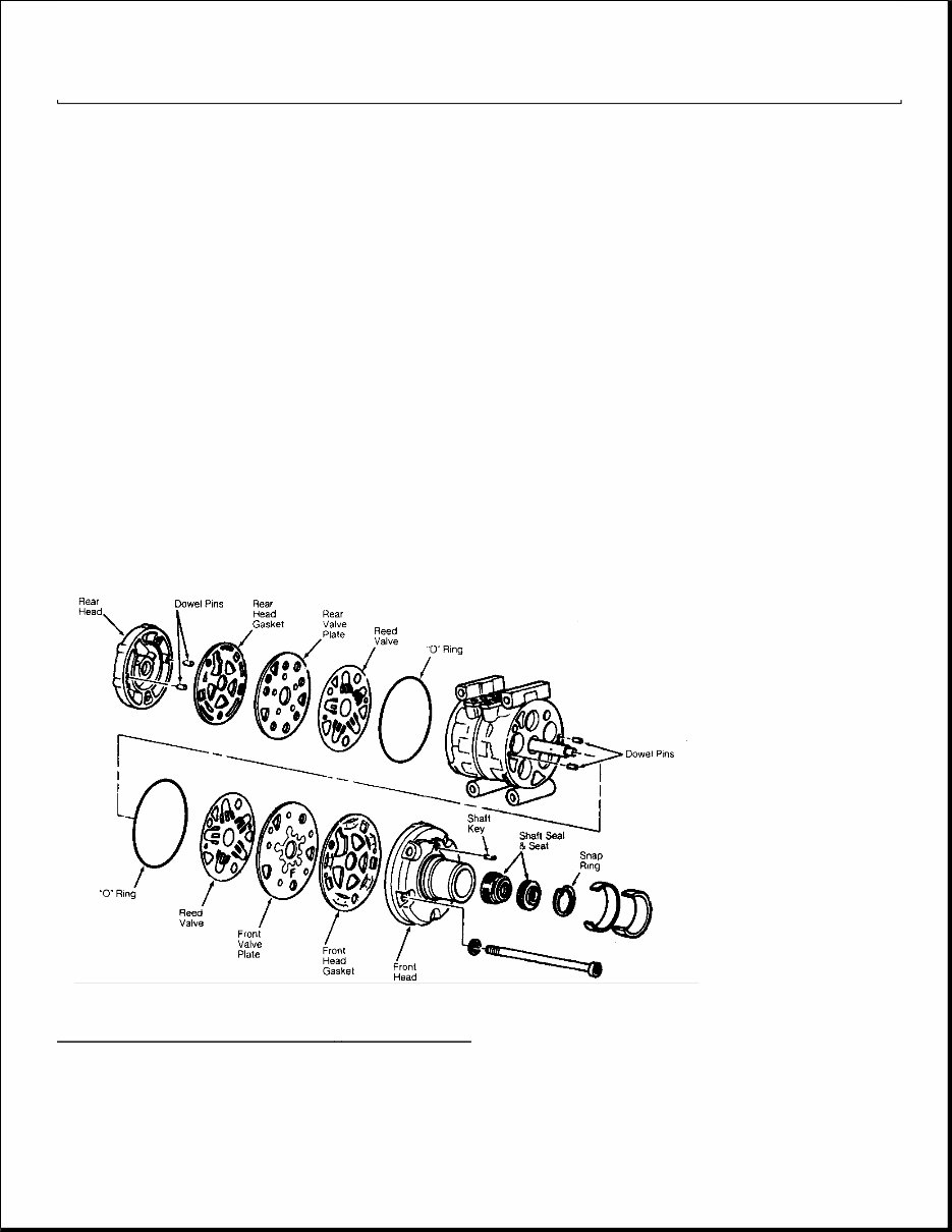
NIPPONDENSO 10P15A Removal 1. Hold pulley assembly with Strap Wrench (D85L-6000-A). Apply battery voltage to clutch coil assembly and remove crankshaft nut. Screw Clutch Plate Remover (T88C-19703-BH) into clutch plate and remove clutch plate from compressor. Remove clutch plate shims. 2. Remove snap ring and clutch pulley assembly. If pulley cannot easily be removed, use plastic hammer and tap pulley from shaft. Remove snap ring. Disconnect electrical wiring and remove clutch coil. Installation 1. Install clutch coil over locating pin and install snap ring. Connect electrical wiring. Install pulley. 2. Ensure pulley bearing is aligned with compressor head. Gently tap pulley on shaft with plastic hammer (if necessary). Install pulley retaining snap ring. 3. Install shims and clutch plate. Install crankshaft nut and tighten to 10-12 ft. lbs. (14-16 N.m). DO NOT tighten nut with air tools. Using feeler gauge, measure clearance between clutch plate and pulley in several different areas. Proper clearance is .016-.028" (.41-.71 mm). If clearance is not correct, add or remove shims. Fig. 2: View of 10P15 & 10P15F 10 - Cyl Compressor Courtesy of FORD MOTOR CO. NIPPONDENSO/FORD 10PA17A
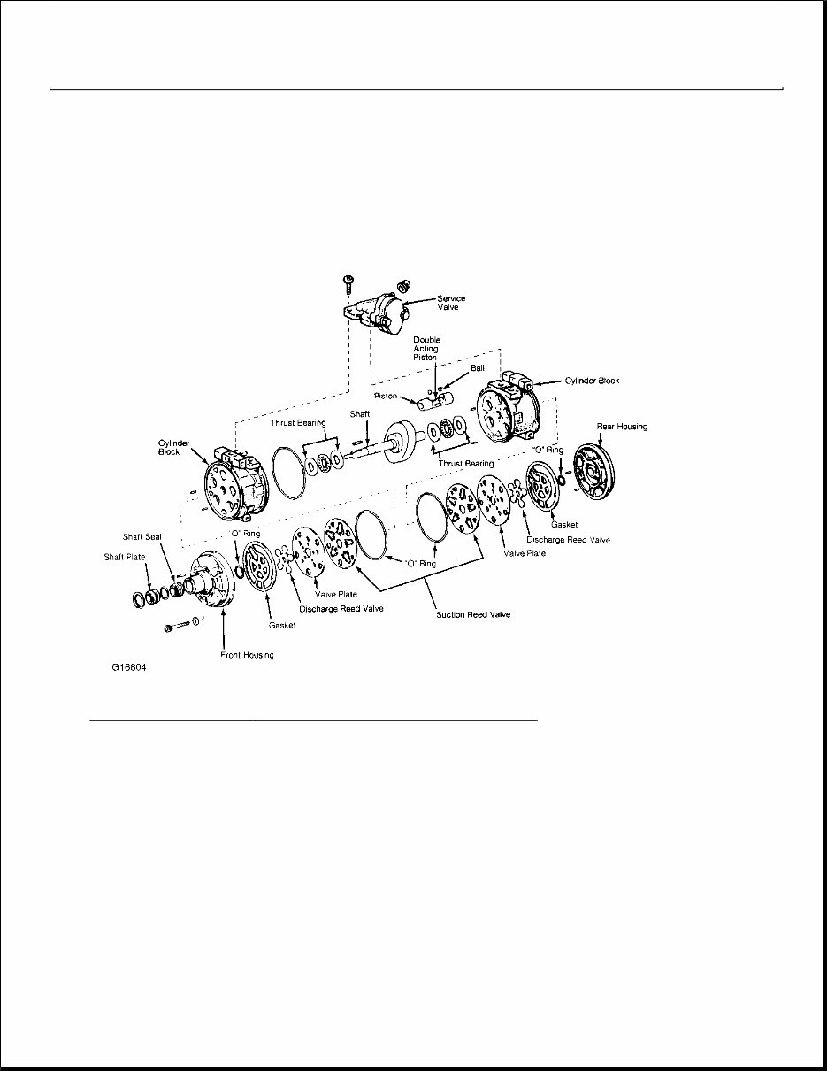
Removal 1. Remove clutch plate retaining bolt and discard. Using 8 mm bolt, thread bolt into crankshaft and remove clutch plate. Remove clutch plate shims. 2. Remove pulley assembly snap ring. Remove pulley assembly. Remove snap ring and disconnect clutch coil electrical wiring. Remove clutch coil. Installation 1. Install clutch coil over locating tab. Install snap ring. Install pulley assembly and install snap ring. Apply a thin coat of White grease to compressor shaft splines. 2. Install clutch plate spacer shims. Slide compressor clutch on crankshaft and install new retaining bolt. Tighten bolt to 96-120 INCH lbs. (11-14 N.m). Using a feeler gauge, rotate clutch assembly and check clearance in 3 places. Proper clearance is .014-.026" (.36-.66 mm). If clearance is not correct, add or remove shims. Fig. 3: Exploded View of Nippondenso 10PA17A 10 - Cyl. Compressor SHAFT SEAL R & I FORD FX-15 10-CYLINDER Removal 1. Remove clutch hub. Using "O" Ring Remover (T71P-19703-C) remove shaft seal felt. Thoroughly clean
seal area of compressor. Using snap ring pliers, remove shaft seal snap ring. 2. Position Shaft Seal Remover (T89P-19623-BH) over compressor shaft and push remover down against seal. Ensure end of remover is in seal and turn remover handle clockwise to expand remover tip. Pull shaft seal straight out. Installation 1. Place a well lubricated Shaft Seal Protector (T89P-19623-CH) over crankshaft. Dip shaft seal in new refrigerant oil and position seal with lip pointing toward compressor. 2. Using Shaft Seal Installer (T89P-19623-AH), slowly push shaft seal down protector until seated. Remove installer and protector. Install shaft seal snap ring. Using seal installer, push on snap ring until it snaps into snap ring groove. Install new shaft seal felt. To complete installation, reverse removal procedure. NIPPONDENSO 10P15, 10P15F Removal 1. Discharge system using approved refrigerant recovery/recycling equipment and remove compressor. Drain oil from compressor and record amount for reassembly. 2. Mount compressor in vise claMFIng on mounting ears. Using Spanner (T81P-19623-MH), hold clutch plate and remove crankshaft nut. Pull clutch plate from compressor using Clutch Plate Remover (T80L- 19703-B). Remove clutch plate shims. 3. Clean compressor front hub area. Remove felt packing and dust seal retainer from inside compressor nose. See Fig. 2 . Using Shaft Key Remover (T81P-19623-NH), remove key from shaft. 4. Remove seal seat retaining snap ring. Clean inner bore of compressor nose. Using Shaft Seat Remover/Installer (T87P-19623-B), remove seal seat. 5. Using Shaft Seal Remover/Installer (T87P-19623-C), remove seal by pushing downward on shaft seal remover/installer and rotating clockwise to engage seal tangs. Pull seal from compressor. Installation 1. Place Shaft Seal Protector (T71P-19703-H) over compressor shaft. Lubricate shaft seal and nose of compressor with new refrigerant oil. DO NOT touch sealing surface of seal or shaft. Engage seal tangs on shaft seal remover/installer. 2. Align flats of seal with flats on crankshaft and push new seal on compressor shaft. Push downward on shaft seal remover/installer and turn counterclockwise to disengage seal tangs. 3. Attach shaft seal seat to shaft seal seat remover/installer and lubricate with new refrigerant oil. Install seal seat and push inward against seal. Install seal seat retaining snap ring. 4. Install dust seal retainer and felt packing. Install clutch plate shims. Ensure clutch plate aligns with crankshaft key. Using Clutch Plate Installer (T80L-19703-F), install clutch plate. 5. Install crankshaft nut. Using spanner to hold clutch, tighten crankshaft nut to 10-14 ft. lbs. (13-20 N.m). DO NOT tighten nut with air tools. 6. Using feeler gauge, check clearance between clutch plate and pulley. Rotate compressor clutch and check clearance in more than one place. Proper clearance is .021-.036" (.53-.91 mm). If clearance is not correct, add or remove shims.
7. Add same amount new refrigerant oil to compressor as was drained. Rotate compressor 10 revolutions to distribute oil. Install compressor. Evacuate and recharge system. Perform leak test. NIPPONDENSO 10P15A Removal 1. Discharge system using approved refrigerant recovery/recycling equipment and remove compressor. Drain oil from compressor and record amount for reassembly. Remove clutch assembly. See NIPPONDENSO 10P15A under CLUTCH ASSEMBLY R & I in this article. 2. Remove manifold assembly from top of compressor. Clean compressor front hub area. Using Ring Remover (T71P-19703-C), remove retaining ring from front of compressor shaft. 3. Remove felt seal from front of compressor. Remove front head retaining bolts and front head from compressor. Remove snap ring from rear of front head. Remove seal from rear of front head. Installation 1. Install seal and snap ring in front head. Install front head on compressor. Tighten bolts to 18-20 ft. lbs. (24-27 N.m). Install felt packing and retaining ring. 2. Install manifold assembly and tighten bolts to 18-20 ft. lbs. (24-27 N.m). Add same amount of new refrigerant oil to compressor as that drained from compressor. Rotate compressor 10 revolutions to distribute oil in compressor. Install compressor. Evacuate and recharge system. Perform leak test. NIPPONDENSO/FORD 10PA17A Removal 1. Install compressor in Holding Fixture (T89P-19623-D) and clamp fixture in a vise. Remove clutch plate, pulley assembly and clutch coil. Using a 6 mm Allen wrench, remove 5 compressor through bolts. Pull front head from compressor using care not to scratch sealing surface. 2. Reach down inside front head and remove felt seal and retainer. Using "O" Ring Remover (T71P-19703- C), remove "O" ring. Position compressor front head nose up on cardboard on flat surface. Using Shaft Seal Remover (T89P-19623-E), push shaft seal from head. Inspect front head for damage to sealing surface. Replace if needed. Installation 1. Lubricate new "O" ring with refrigerant oil and install. Using Shaft Seal Installer (T89P-19623-F), press seal into front head. Install felt seal and retainer. 2. Install a well lubricated Shaft Seal Protector T89D-19623-C) on crankshaft. Install a new front head "O" ring on compressor housing and coat with refrigerant oil. 3. Position front head on compressor aligning dowel pins. Use care when guiding shaft seal protector through seal opening. Remove shaft seal protector. Install 5 compressor through bolts using new brass washers. Diagonally tighten bolts to 19 ft. lbs. (26 N.m). To complete installation, reverse removal procedure.
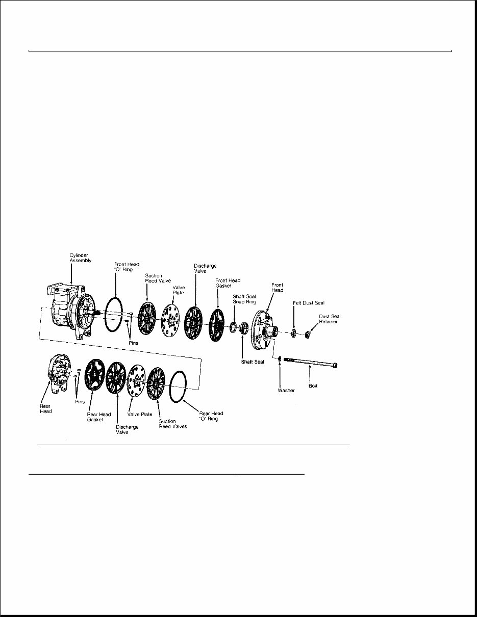
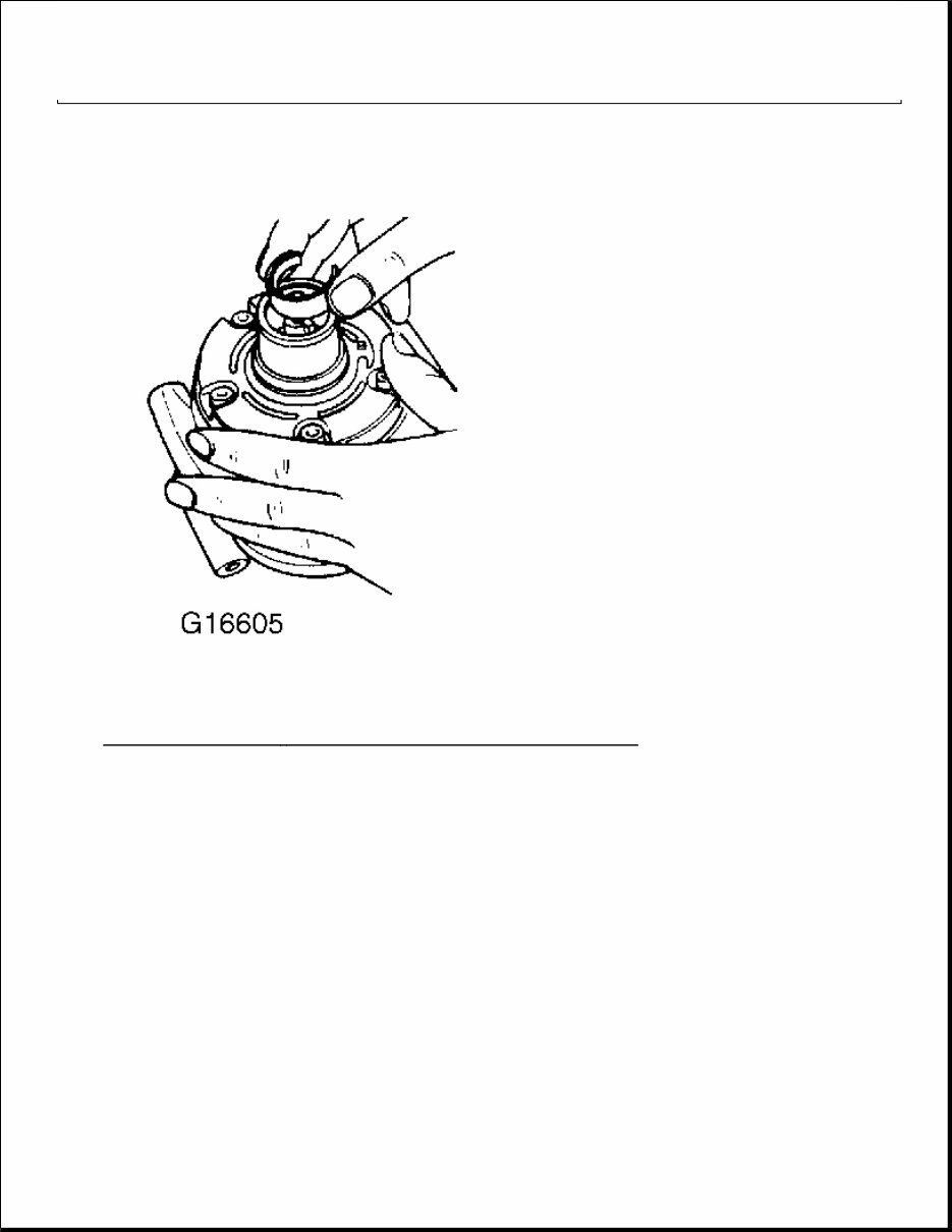
SEAL REPLACEMENT NIPPONDENSO EXCEPT 10PA17A 1. Remove Clutch Coil - Refer to CLUTCH COIL REPLACEMENT in this article. Remove inner felt with needle nose pliers. Fig. 4: Nippondenso 10 - Cylinder Compressor (Except 10PA17A)
Fig. 5: Removing Felt - Nippondenso Except 10PA17A Compressor 2. Remove Internal Snap Ring - Remove the internal snap ring with internal snap ring pliers.
The 1990 Ford Taurus Service & Repair Manual provides instructions for maintaining and repairing Taurus models equipped with the 3.0L SFI Vulcan V6. Designed for both professional mechanics and DIY owners, it lays out step-by-step procedures backed by technical specifications and service data.
Inside, you’ll find detailed coverage of engine testing, overhaul procedures, and fuel system servicing, along with complete guidance on cooling, exhaust, and emission control systems. Transmission and driveline sections cover both automatic gearbox service and axle troubleshooting, while brake, suspension, and steering system chapters include inspection, adjustment, and component replacement procedures.
Content overview:
Complete general information and safety guidelines
Full coverage of engine mechanical, engine testing, and overhaul procedures
Air intake, cooling system, and exhaust system service and troubleshooting
Detailed fuel injection system, fuel pump, and EVAP system instructions
Automatic transmission (AT) diagnosis, service, removal, and overhaul
Clutches and driveline/axle service, including front and rear axle troubleshooting
Brake system bleeding, disc, drum, and parking brake service
Suspension systems (front and rear) with wheel alignment specs and theory
Steering system diagnostics: power steering, steering gear, steering column, and switches
Electrical system and wiring diagrams with component locations and troubleshooting
HVAC system repair, heating and air conditioning troubleshooting, and diagnosis
Computer relearn procedures, EEC theory, and electronic controls
Emission control system: EGR, catalytic converter, thermactor, and related components
Interior and body systems: seats, mirrors, windshield, windows, and power accessories
Lighting, instrument panel, ignition, starter, and service indicators
Keyless entry, trunk release, and autolamp system coverage
Vacuum diagrams, fuse and circuit breaker locations, and drive belt routing
Full set of wiring diagrams for complete electrical troubleshooting
Printable: Yes Language: English Compatibility: Pretty much any electronic device, incl. PC & Mac computers, Android and Apple smartphones & tablet, etc. Requirements: Adobe Reader (free)