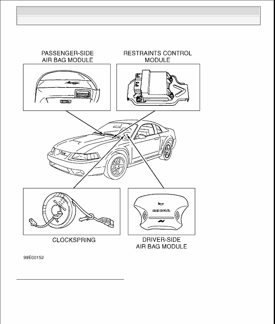
AIR BAG RESTRAINT SYSTEM 1999 Ford Motor Co. DESCRIPTION & OPERATION The Supplemental Restraint System (SRS) is designed to provide increased accident protection for driver and passenger by deploying air bags in a front-end collision. The air bags, stored in center of steering wheel and in instrument panel above glove box, deploy in about 40 milliseconds after impact sensors close. Air bag system is designed to be used with 3-point safety belts. During a front-end collision of sufficient force, impact and safing sensors will activate simultaneously to inflate air bag. When impact sensor and safing sensor are closed at same time, electrical current will flow, igniting the driver-side and passenger-side air bag module. Air bag system includes following components: Restraints Control Module (RCM) or diagnostic monitor, driver-side air bag module, passenger-side air bag module, AIR BAG warning light, impact sensor (in RCM), safing sensor (in RCM), ignitor assemblies (in air bag modules), clockspring (also known as sliding contact) and associated wiring harnesses. See Fig. 1 . WARNING: To avoid injury from accidental air bag deployment, read and carefully follow all WARNINGS and SERVICE PRECAUTIONS . 1999 Ford Mustang AIR BAG RESTRAINT SYSTEM 1999 Ford Motor Co. 1999 Ford Mustang AIR BAG RESTRAINT SYSTEM 1999 Ford Motor Co.
Fig. 1: Locating Restraint System Components Courtesy of FORD MOTOR CO. BACK-UP POWER SUPPLY Back-up power supply is located inside restraints control module. If battery or battery cables are damaged in a collision, back-up power supply will supply electrical power to deploy air bags. Back-up power supply will hold a deployment charge for approximately one minute after battery is disconnected. 1999 Ford Mustang AIR BAG RESTRAINT SYSTEM 1999 Ford Motor Co.
CLOCKSPRING The steering column contains a clockspring assembly (also known as sliding contact) to transfer electrical signals from steering column wiring harness to driver-side air bag module. Clockspring is mounted on the steering column between combination switch and steering wheel. DRIVER-SIDE AIR BAG MODULE The driver-side air bag module is mounted on front face of steering wheel, covered by steering wheel trim cover. When impact and safing sensors close, signaling an impact, ignitor triggers inflator. During ignition, sodium azide reacts with copper oxide, producing nitrogen gas, which inflates air bag. When air bag deploys, tear-seams molded into steering wheel trim cover separate, allowing inflation of air bag assembly. Driver-side air bag module is not serviceable and must be replaced as a complete assembly. PASSENGER-SIDE AIR BAG MODULE The passenger-side air bag module is mounted in right side of instrument panel, above glove box. When impact and safing sensors close, signaling an impact, air bag igniters trigger inflator. Since passenger-side air bag is larger than driver-side air bag, inflator contains more gas generant in a different configuration to produce more gas. When air bag is activated, instrument panel trim cover tears at seams and hinges, allowing inflation. Passenger-side air bag module is only serviced as a complete assembly. RESTRAINTS CONTROL MODULE (RCM) The Restraints Control Module (RCM) is located on center tunnel below climate control assembly. See Fig. 1 . The RCM contains a microcomputer, which monitors electrical system components and connections. RCM performs a system self-check of air bag system internal circuits every time ignition switch is turned to RUN position. RCM also illuminates the AIR BAG warning light during initial system self-check and flashes a Lamp Fault Code (LFC) whenever a fault is detected. If a system fault exists and/or AIR BAG warning light is malfunctioning, an audible tone will sound, indicating need for service. ELECTRICAL SYSTEM Air bag system is powered from battery through ignition circuit. System can function when driver-side and passenger-side seats are unoccupied. The 3 main functions performed by electrical subsystem are: detecting an impact, switching electric power to igniters for air bags, and monitoring readiness of air bag system. SERVICE PRECAUTIONS The following precautions should be observed when working with air bag system: Disable air bag system before servicing any air bag system or steering column components. Failure to do so may result in accidental air bag deployment and personal injury. See procedures under DISABLING 1999 Ford Mustang AIR BAG RESTRAINT SYSTEM 1999 Ford Motor Co.
& ACTIVATING AIR BAG SYSTEM . Wait one minute after disabling air bag system before working on vehicle. Back-up power supply holds a deployment charge for approximately one minute after negative battery cable is disconnected. Servicing air bag system before one minute may cause accidental air bag deployment and possible personal injury. Because of critical system operating requirements, DO NOT service clockspring, restraints control module or air bag modules. Repairs are made by replacement only. Always wear safety glasses whenever servicing an air bag equipped vehicle or handling an air bag. When carrying a live air bag module, ensure air bag module and trim cover are pointed away from your body. This minimizes chance of injury in event of an accidental deployment. When placing a live air bag module on a bench or other surface, always face air bag module and trim cover facing up and away from surface. This will reduce motion of module if it is accidentally deployed. After deployment, air bag surface may contain deposits of sodium hydroxide, which may irritate skin. Sodium hydroxide is a product of gas generant combustion. Always wear gloves and safety glasses when handling a deployed air bag. Wash your hands using mild soap and water. Follow correct disposal procedures. See DISPOSAL PROCEDURES . If scrapping a vehicle with an undeployed air bag module, air bag must be deployed. See DISPOSAL PROCEDURES . If a part is replaced and new part does not correct condition, reinstall original part and perform diagnostic procedure again. Never probe connectors on air bag module. Doing so may cause air bag deployment and/or personal injury. Instruction to disconnect always refers to connector. DO NOT remove component from vehicle if instructed to disconnect. After any servicing, ensure AIR BAG warning light does not indicate any fault codes. See SYSTEM OPERATION CHECK . Replace air bag module if trim cover (deployment doors) is marred or damaged. DO NOT repaint trim cover. Paint may degrade cover material. Replace air bag module as necessary. See SCRAPPED VEHICLE under DISPOSAL PROCEDURES . If vehicle is involved in collision in which center tunnel area is damaged, inspect RCM mounting bracket for deformation. If damaged, RCM must be replaced whether or not air bags have deployed. Additionally, ensure RCM mounting area is restored to its original condition. ADJUSTMENTS CLOCKSPRING Information is not available from manufacturer. Wiring from clockspring to air bag module must align with hole in steering wheel. If wiring is not aligned properly, wiring may be damaged when steering wheel is installed and rotated. DISABLING & ACTIVATING AIR BAG SYSTEM WARNING: Wait one minute after disabling air bag system before working on vehicle. 1999 Ford Mustang AIR BAG RESTRAINT SYSTEM 1999 Ford Motor Co.
DISABLING SYSTEM For Component Replacement Record pre-set radio frequencies for reprogramming (if equipped). Disconnect negative battery cable. Wait at least one minute for back-up power supply to deplete stored energy. For Diagnosis & Testing 1. Record pre-set radio frequencies for reprogramming. Disconnect negative battery cable. Wait at least one minute for back-up power supply to deplete stored energy. 2. Remove driver-side air bag module. See DRIVER - SIDE AIR BAG MODULE under REMOVAL & INSTALLATION. Connect Air Bag Simulator (105-R0012) to clockspring connector at top of steering column (in place of air bag). See Fig. 2 . 3. Remove passenger-side air bag module. See PASSENGER - SIDE AIR BAG MODULE under REMOVAL & INSTALLATION. Connect Air Bag Simulator (105-R0012) to passenger-side air bag vehicle harness connector (in place of air bag). Connect negative battery cable. To reactivate air bag system, see ACTIVATING SYSTEM . AIR BAG SIMULATOR To remove risk of accidental air bag deployment while diagnostics are performed, an Air Bag Simulator (105- 00012) or equivalent is required. See Fig. 2 . An air bag simulator is a 2-ohm resistor with appropriate connector and is used to simulate air bag module connection to the system. DO NOT short-circuit air bag module connections with a zero-ohm jumper wire. If zero-ohm jumper is used, a Light Flash Code (LFC) will be displayed. Back-up power supply holds a deployment charge for approximately one minute after negative battery cable is disconnected. Servicing air bag system before one minute may cause accidental air bag deployment and possible personal injury. CAUTION: When battery is disconnected, vehicle computer and memory systems may lose memory data. Driveability problems may exist until computer systems have completed a relearn cycle. See COMPUTER RELEARN PROCEDURES in GENERAL INFORMATION. WARNING: DO NOT use radio key code (memory) savers when working on air bag system. Unintentional air bag module deployment and personal injury may result. 1999 Ford Mustang AIR BAG RESTRAINT SYSTEM 1999 Ford Motor Co.
Introducing the FORD MUSTANG 1994-99 Service Repair Manual. This comprehensive manual is specially designed to assist owners in maintaining and repairing their Ford Mustang models from 1994 to 1999. With detailed step-by-step instructions, diagrams, illustrations, and specifications, this manual is a must-have for all Mustang enthusiasts.
This Service Repair Manual covers a wide range of Mustang models, including:
FORD MUSTANG 1994
FORD MUSTANG 1995
FORD MUSTANG 1996
FORD MUSTANG 1997
FORD MUSTANG 1998
FORD MUSTANG 1999
Whether you need to perform routine maintenance or tackle more complex repairs, this manual provides the necessary guidance and information you need. From engine troubleshooting to electrical system repairs, suspension adjustments to brake replacements, this manual covers it all.
Invest in the FORD MUSTANG 1994-99 Service Repair Manual and empower yourself with the knowledge and confidence to keep your Mustang running smoothly. Experience the joy of DIY repairs and save on costly visits to the mechanic. Order your copy today!