DESCRIPTION AND OPERATION > ABOUT THIS SERVICE INFORMATION > INTRODUCTION WARNING: Before beginning any service procedure in this article, refer to health and safety warnings in this article. Failure to follow this instruction may result in serious personal injury. For additional information, refer to: Health and Safety Precautions . This article describes and directs repair procedures specified by Ford Motor Company for the vehicle. Critical health and safety precautions are included. Anyone who deviates from these instructions risks compromising personal safety or vehicle integrity. ARTICLE CONTENT This service information is divided into articles. Article contents may include: Specifications Fluid capacities, component specifications and torque values not covered in other procedures Description and Operation Overview of the system, component locations, and system operation Diagnosis and Testing Symptom charts, DTC charts and diagnostic tests See the Diagnosis and Testing Information in this article General Procedures Service adjustments, electronic programming and other special procedures Removal and Installation Component removal and installation instructions Removal Component removal instructions Installation Component installation instructions Disassembly and Assembly Component disassembly and assembly instructions Service Manual: GENERAL INFORMATION Ford Mustang
Disassembly and Assembly of Subassemblies Assembly disassembly and assembly instructions IMPORTANT INFORMATION General Information articles contains the following important information (including this article): Critical Health and Safety Precautions - service safety precautions applicable to the entire article. For additional information, refer to: Health and Safety Precautions . A Symbols Glossary - definitions of the action directed by each symbol. For additional information, refer to: Symbols Glossary . Diagnostic Methods - support information for diagnostics. DESCRIPTION AND OPERATION > ABOUT THIS SERVICE INFORMATION > WARNINGS, NOTICES AND NOTES WARNINGS Warnings provide information to avoid personal injury and to make sure service actions on critical safety systems are performed correctly. Warnings that apply to an entire system or service information article are located in Health and Safety Precautions . NOTICES (in some publications, CAUTIONS) Notices provide information to avoid damage to the vehicle or a component. NOTES Notes provide information critical for a complete and effective repair. Warnings, Notices, or Notes that apply to an entire procedure will be placed at the beginning of the procedure. Warnings, Notices, or Notes that apply to a single step are placed at the beginning of the step. Those that apply to a group of steps will be placed at the first step requiring it. DESCRIPTION AND OPERATION > ABOUT THIS SERVICE INFORMATION > SPECIFIED CHEMICALS OR MATERIALS Throughout this service information, chemicals or materials are specified that must be used to properly complete a service procedure or diagnostic step. In the event a specific material is not readily available, a substitute material meeting the same specification may be used. Ford has not reviewed third party products for compliance with environmental, health or safety regulations and is not responsible for their use. Use of third party products is at your own risk. Additionally, such products may cause degraded performance, premature failures, and/or vehicle component damage. All chemicals or materials used for vehicle servicing should be checked for compliance with local environmental and health and safety regulations.
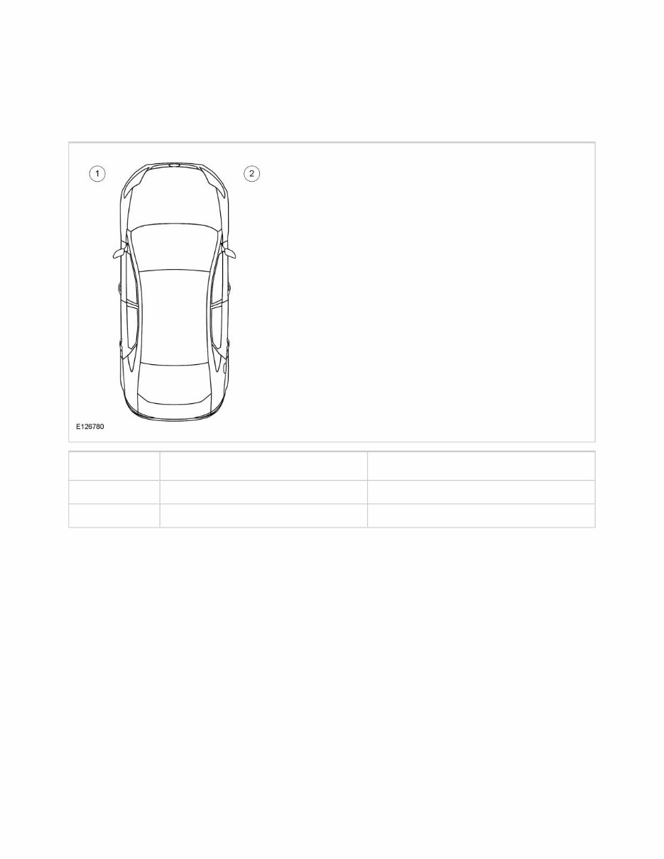
DESCRIPTION AND OPERATION > ABOUT THIS SERVICE INFORMATION > LH AND RH DESIGNATIONS All LH and RH designations are oriented from the driver's seat position looking forward. Vehicle LH and RH definition Item Part Number Description 1 - LH (left-hand) 2 - RH (right-hand) All LH and RH engine designations are oriented from the flywheel position looking toward the crankshaft pulley. Powertrain LH and RH definition
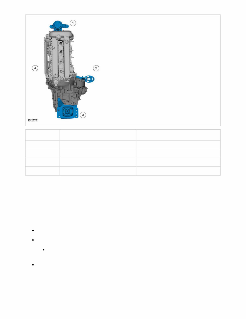
Item Part Number Description 1 - Front 2 - RH (right-hand) 3 - Rear 4 - LH (left-hand) DESCRIPTION AND OPERATION > ABOUT THIS SERVICE INFORMATION > STANDARD PRACTICES The following rules apply, unless specified differently in the procedure: FASTENERS Reuse standard fasteners. Replace fasteners with self-locking features. Examples of fastener self-locking coatings or mechanical locking (with the locking features highlighted yellow) are shown in the illustration. Replace fasteners with torque angle specifications (those tightened a specified number of degrees). Examples of self-locking nuts and bolts
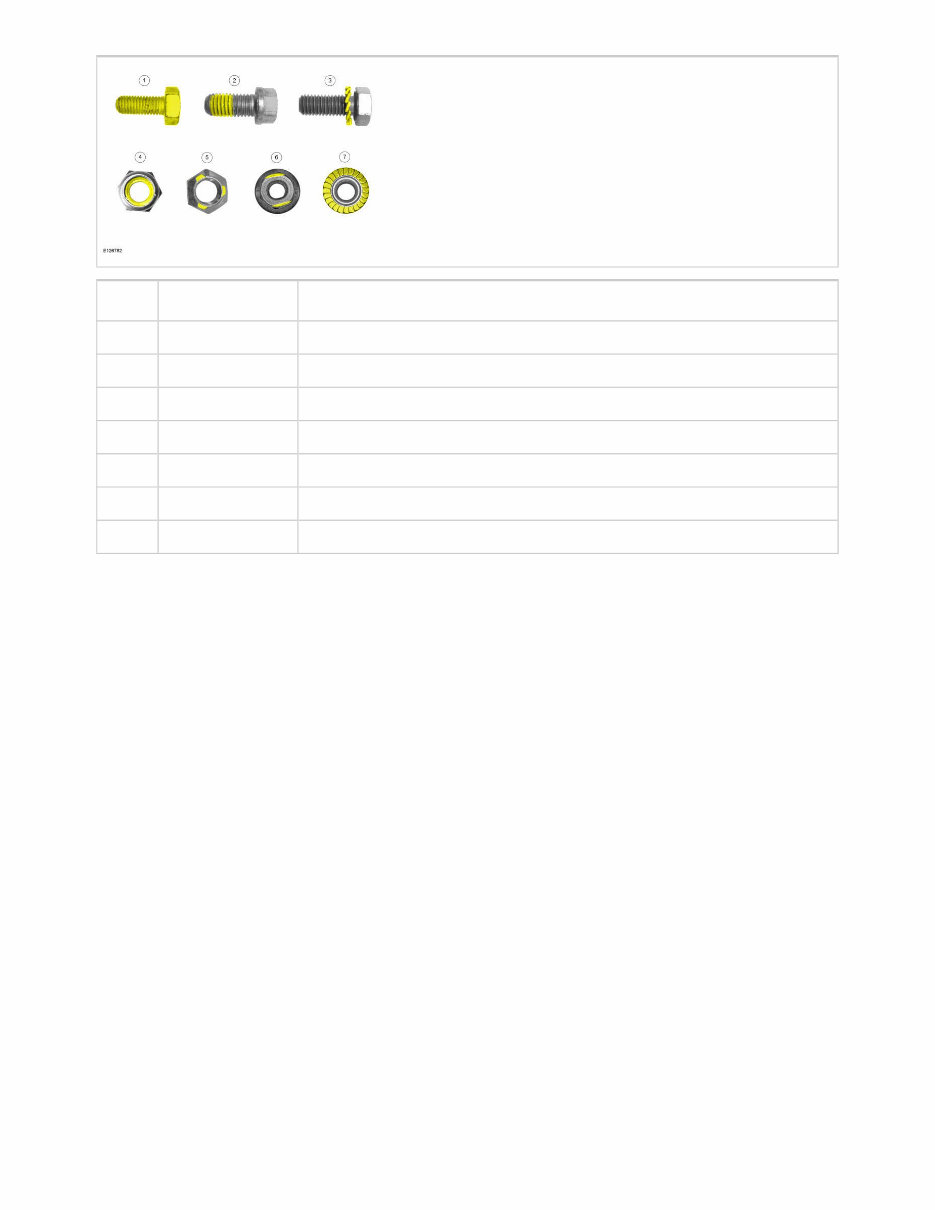
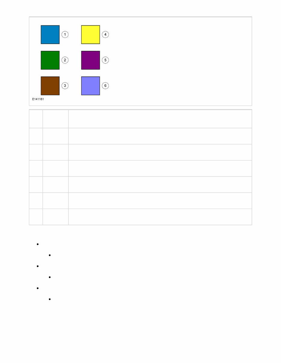
Item Part Number Description 1 - Completely coated self-locking bolt 2 - Partially coated self-locking bolt 3 - Self-locking bolt with a locking washer 4 - Self-locking nut with a plastic locking insert 5 - Self-locking nut with thread deformation (3 indentations) 6 - Self-locking nut with thread deformation (to oval shape) 7 - Self-locking nut with integrated locking ring SEALS AND GASKETS Replace seals and gaskets, unless specified differently in the procedure. EXTERIOR TRIM PARTS Replace exterior trim parts fastened with glue or adhesive tape, unless specified differently in the procedure. DESCRIPTION AND OPERATION > ABOUT THIS SERVICE INFORMATION > MECHANICAL PROCEDURES Illustrations in this service information may be used instead of written step instructions. Color-coding (see color scheme illustration) is used to communicate the required step action or actions. Service action icons may be used to add information regarding the required action. For additional information, refer to: Symbols Glossary . Illustration Color-coding
Item Part Number Description 1 - Blue - Target or primary component to be removed/installed (or disassembled/assembled). 2 - Green - Components that need to be removed prior to or installed after the target/primary. 3 - Brown - Components that need to be removed prior to or installed after the target/primary. 4 - Yellow - Components to be set aside for access, but not removed. Also highlighted areas to inspect or adjust. 5 - Magenta - Electrical connectors and fasteners such as nuts, bolts, clamps, or clips to be: detached, attached, loosened, moved, removed or installed. 6 - Pale Blue - Special tool(s), general equipment, or common tools used in an uncommon way. Other color coding Alternating Blue and White Chemical, adhesive or sealer apply areas Red Sectioned or cut-away areas Grey Background components shown for location information ILLUSTRATION TASK SEQUENCE Components that must be removed or installed in a specific sequence are identified with a numbered callout. Any associated step text is numbered accordingly. Simple procedure example showing color-coding and task sequence.
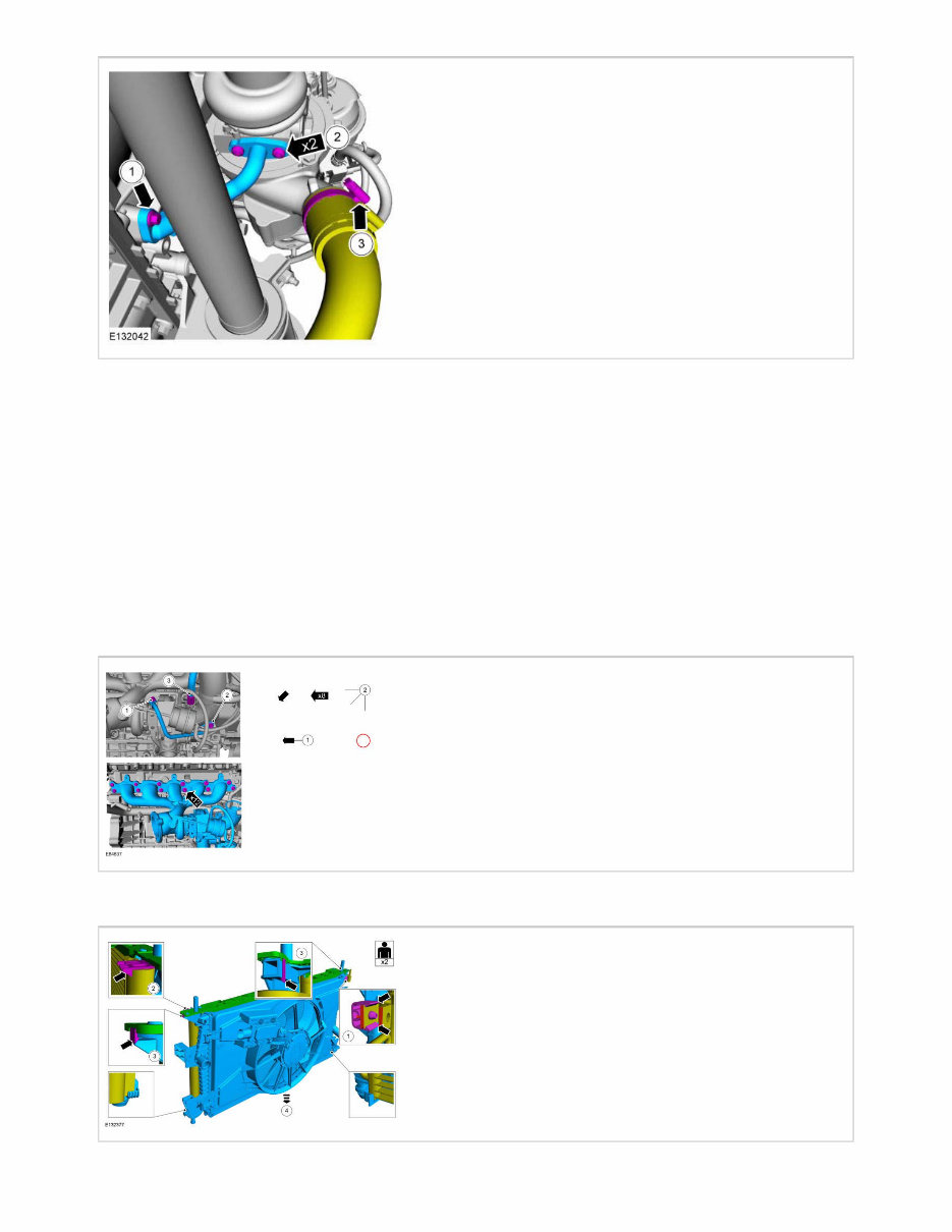
Black arrows are used to draw attention to components (usually fasteners). Arrows with multiples specified (here, x2) identify an identical number of fasteners or items. Callouts (numbers inside circles) show a required sequence or tightening torque. In the illustration, the callouts indicate the removal sequence, which is reversed for installation . The yellow coloring of the hose indicates it is to be positioned aside (not removed). Two identical (magenta- colored) fasteners are indicated by the x2 arrow. The fasteners in this illustration require different torques (same torque for the x2 fasteners) so numbered callouts are used to identify them with torque values in the associated step text. The (magenta-colored) hose clamp is another fastener to be removed. Examples of fastener removal sequence and an identical service action for 12 fasteners. Other possible symbols are shown on the right. Example of fastener sequence information with two persons required for the service action
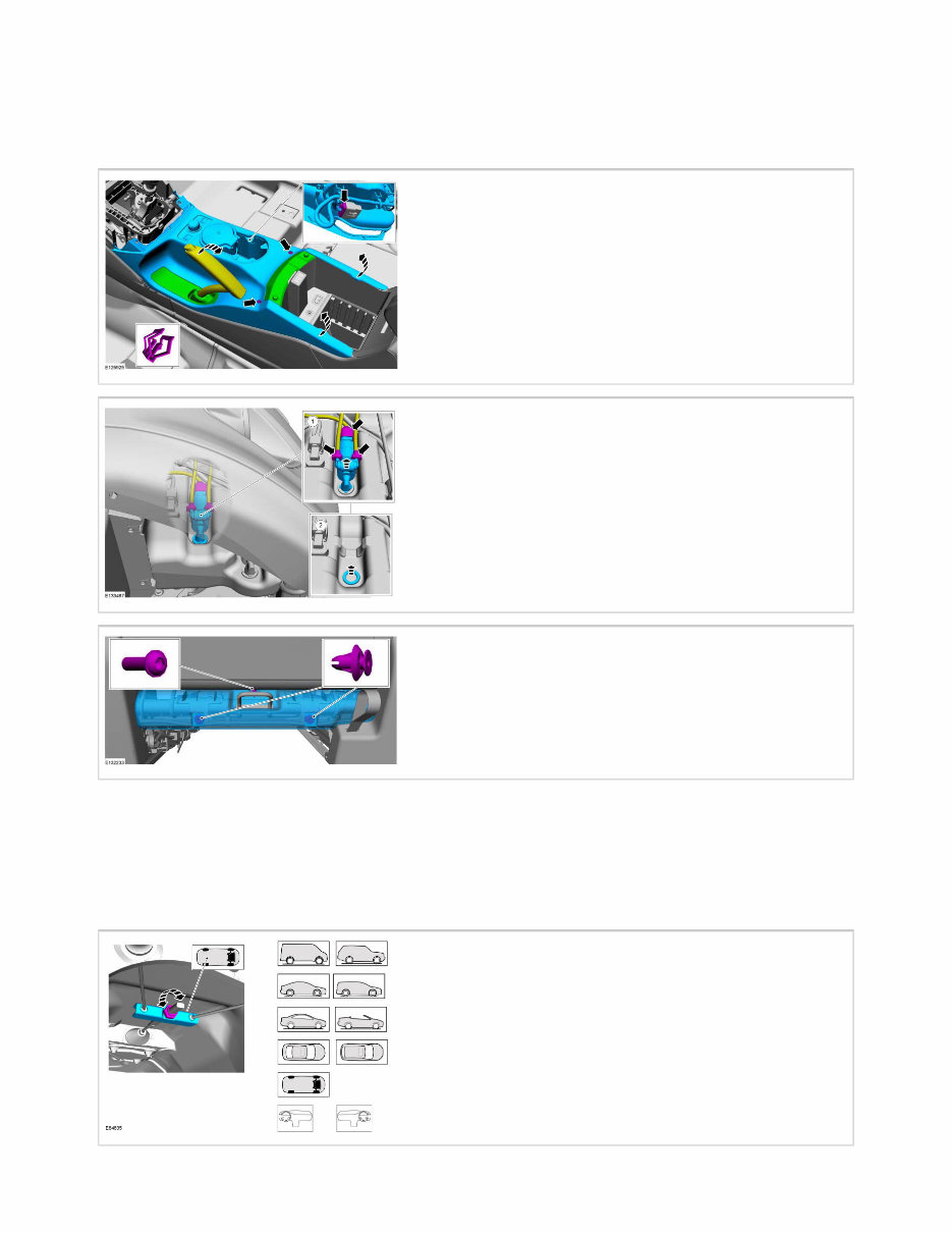
HIDDEN DETAILS Separate detail boxes or transparent components may be used to show hidden items in an illustration. Example of hidden fastener information SERVICE ACTION ICONS Service action icons may be used to add information regarding the required action. For additional information, refer to: Symbols Glossary . Location symbols show the location of a component or system on the vehicle.
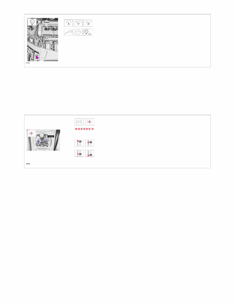
Example of service action icons pointing to highlighted components. Movement arrows and service action icons show three dimensional or rotational movements. Color-coding and service action icons show application of sealer, lubricant, weight, tape or cleaning liquid. Measurement symbols provide the information required to perform a specific measurement. These symbols may include specific values.
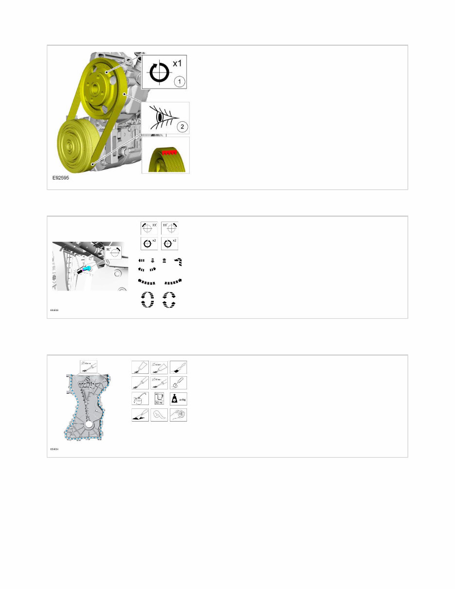
SPECIAL TOOLS, EQUIPMENT, MATERIALS AND TORQUE VALUES When Ford special tools are required for the procedure, the tool and tool number are shown in an illustration. Special tool numbers, general equipment, materials or torque values for the procedure step are shown in the text steps. Example of special service tool and symbol used to hold the gear shift in the required gear position. Other possible symbols are shown on the right. Example of two illustrations used together with sequence steps, service action icons and special service tools
The 2014-2017 Ford Mustang Service & Repair Manual provides factory procedures for models equipped with the 2.3L EcoBoost turbo I4, 3.7L Cyclone V6, and 5.0L Coyote V8 engines. Designed for both professional mechanics and Mustang owners, it includes complete specifications, service intervals, and detailed repair steps.
This manual covers essential systems such as engine mechanical repair and performance diagnostics, transmission service and overhaul, brake system maintenance, driveline and axle repair, and suspension adjustments with alignment procedures. It also details procedures for HVAC servicing, steering system repairs, and restraint system maintenance for seat belts and airbags.
Content overview:
General vehicle information, service specifications, and repair guidelines
Accessories, equipment, and interior component servicing procedures
Body and frame repair, structural components, and exterior panel replacement
Brake system diagnostics, maintenance, and repair procedures
Driveline and axle servicing, including differential and driveshaft repairs
Electrical system diagnostics, wiring, and component replacement
Engine mechanical repairs, specifications, and assembly procedures
Engine performance testing, tuning, and troubleshooting
Heating, ventilation, and air conditioning (HVAC) diagnostics and servicing
Scheduled maintenance procedures and service intervals
Restraint system repair, including seat belts and airbags
Steering system diagnostics, adjustments, and component replacement
Suspension repair and alignment procedures
Transmission servicing, overhaul, and adjustment procedures
Complete wiring diagrams for troubleshooting and electrical repairs
Additional chapters address body and frame repairs, interior and exterior equipment servicing, and electrical system troubleshooting with component replacement. With factory-approved data and step-by-step instructions, this OEM manual is a dependable resource for maintaining and repairing the 2014-2017 Ford Mustang.
Printable: Yes Language: English Compatibility: Pretty much any electronic device, incl. PC & Mac computers, Android and Apple smartphones & tablet, etc. Requirements: Adobe Reader (free)