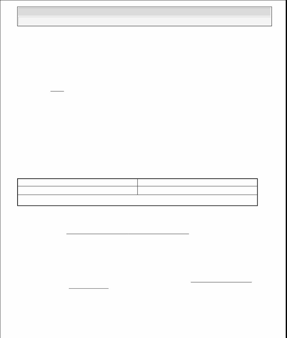
GENERATOR - 4.6L 1998 STARTING & CHARGING SYSTEMS Ford Motor Co. - Mitsubishi Generators DESCRIPTION Generators have an internal fan and electronic voltage regulator. Voltage regulator is part of the brush holder assembly. See Fig. 3 . Voltage regulator incorporates temperature compensation circuitry, so battery charging voltage is maintained at the optimum level. Charging system voltage is maintained within an operating range of 14.1-14.7 volts. ADJUSTMENTS BELT TENSION See BELT TENSION SPECIFICATIONS table. BELT TENSION SPECIFICATIONS TROUBLE SHOOTING ON-VEHICLE TESTING GENERAL INSPECTION Ensure battery posts and cables are clean and tight. Check drive belt tension. Ensure connections at generator, regulator and engine ground are clean and tight. Check fusible links and replace as necessary. NOTE: The terms generator and alternator are interchangeable. Either may be found within illustrations. Application Belt Deflection In. (mm) Mustang (1) (1) Uses automatic belt tensioner. NOTE: See TROUBLE SHOOTING - BASIC PROCEDURES article in GENERAL TROUBLE SHOOTING section. CAUTION: When battery is disconnected, vehicle computer and memory systems may lose memory data. Driveability problems may exist until computer systems have completed a relearn cycle. See COMPUTER RELEARN PROCEDURES article in GENERAL INFORMATION before disconnecting battery. 1998 Ford Mustang GENERATOR - 4.6L 1998 STARTING & CHARGING SYSTEMS Ford Motor Co. - Mitsubishi Generators 1998 Ford Mustang GENERATOR - 4.6L 1998 STARTING & CHARGING SYSTEMS Ford Motor Co. - Mitsubishi Generators
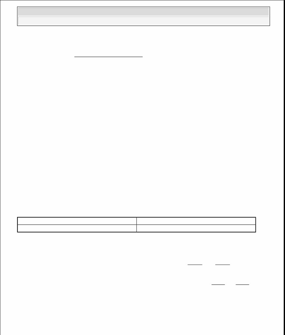
Turn ignition on and ensure charge warning light operates. Check bulb and circuit if necessary. Start engine and verify charge warning light goes out. If warning light goes out, see AMPERAGE OUTPUT TEST. If warning light does not go out, see VOLTAGE OUTPUT TEST . There are 4 conditions that can cause charge indicator light to come on: No Generator Output Overcharging Generator Output Wire Open Voltage Sensing Wire (Terminal "A" Circuit) Open Check Gray or White fuse links (usually located near starter relay). AMPERAGE OUTPUT TEST 1. Ensure drive belt is in good condition and properly tightened. Connect charging system load tester in accordance with manufacturer's instructions. Start and run engine at 2000-3000 RPM and apply load until generator output levels off. 2. Record maximum generator output current. See GENERATOR OUTPUT SPECIFICATIONS table for output values. If generator output is 10-20 percent of rated output amperage, generator output is okay. If generator does not produce rated output, go to VOLTAGE OUTPUT TEST. GENERATOR OUTPUT SPECIFICATIONS VOLTAGE OUTPUT TEST 1. Ensure battery is fully charged. Turn ignition switch to RUN position and leave engine off. Battery voltage should be present at terminals "B+" and "A" at generator connector. See Fig. 1 and Fig. 2 . Approximately one volt should be present at terminal "I". If voltages are correct, go to next step. If voltages are not correct, go to step 3). 2. Start engine and run at 2000 RPM. With generator connected, check voltage at terminals "B+", "A" and "I". At terminals "B+" and "A", 14.1-14.7 volts should be present. At terminal "I", 13-14 volts should be present (engine running). If voltages are not correct, go to next step. If voltages are correct, go to step 4). 3. Check all fuses and fusible links. If fuses are okay, test "B+", "A" and "I" circuits for open, short and excessive resistance. Repair as necessary. If circuits are okay, go to next step. NOTE: Low state of battery charge may occur on vehicles operated under frequent stop and start conditions in high temperatures, coupled with high electrical loads. A new pulley and belt kit is available from manufacturer to correct this condition. Application Amps Rating Mustang 130 NOTE: On some generators, terminal "A" may be identified as terminal "S", and terminal "I" may be identified as terminal "L". See Fig. 1 and Fig. 2 . 1998 Ford Mustang GENERATOR - 4.6L 1998 STARTING & CHARGING SYSTEMS Ford Motor Co. - Mitsubishi Generators
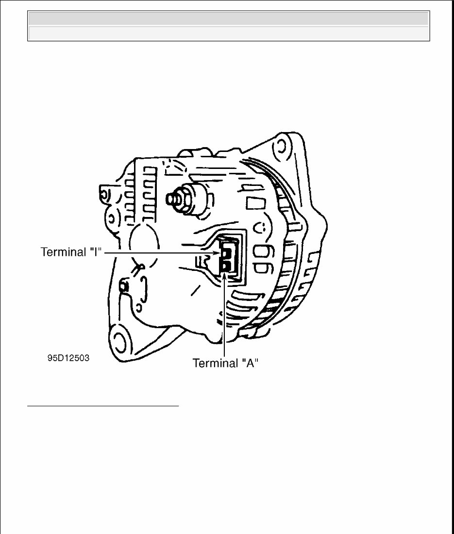
4. Perform voltage drop test on "B+" circuit (between positive battery and terminal "B+" on generator). If voltage drop is .5 volt or more, repair wire between terminal "B+" and positive battery. If voltage is still not correct, repair or replace generator. Fig. 1: Identifying Generator Terminals Courtesy of FORD MOTOR CO. 1998 Ford Mustang GENERATOR - 4.6L 1998 STARTING & CHARGING SYSTEMS Ford Motor Co. - Mitsubishi Generators
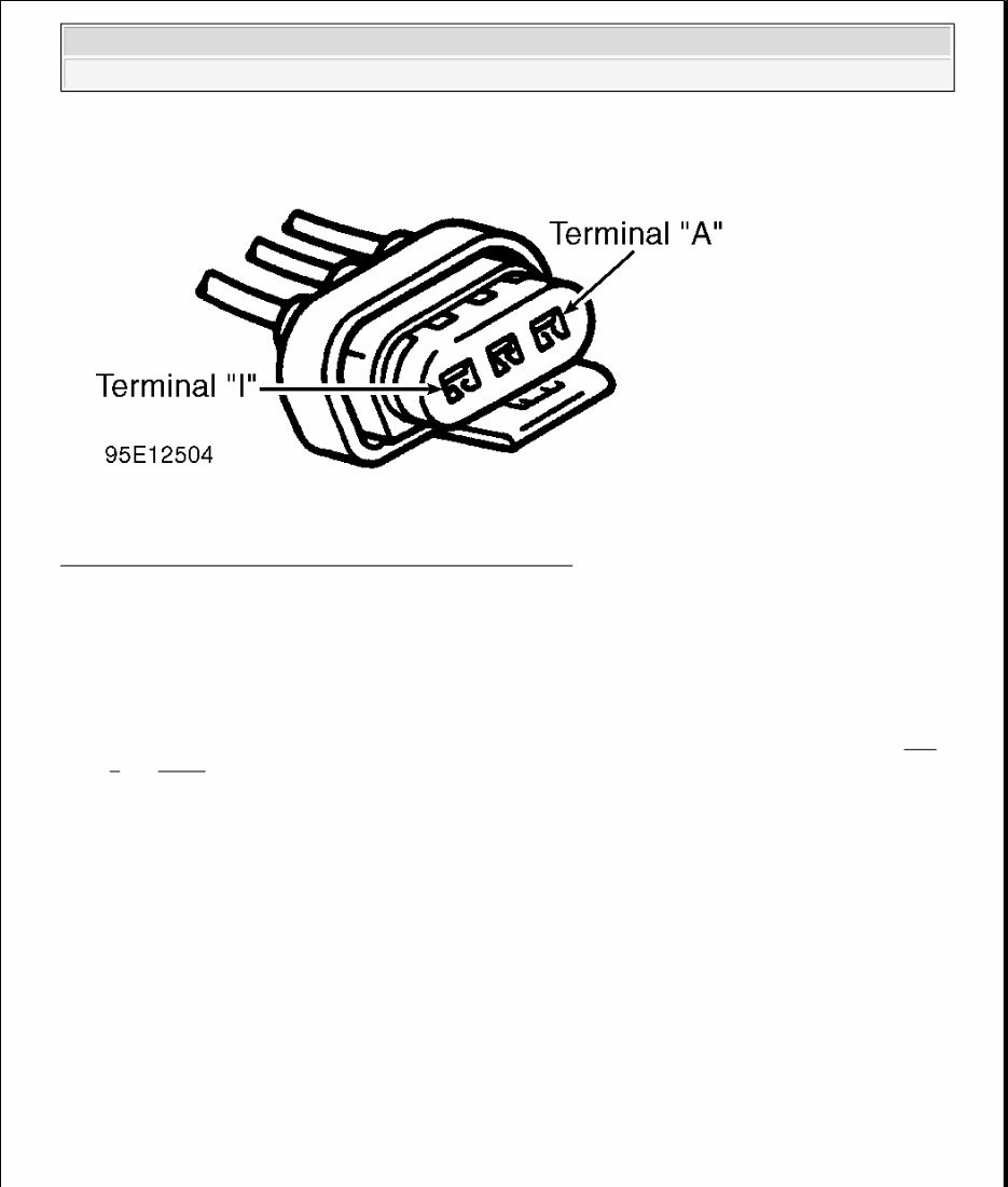
Fig. 2: Identifying Generator Connector Terminals (Typical) Courtesy of FORD MOTOR CO. OVERCHARGE TEST 1. Check battery voltage with engine running at 2000 RPM. If battery voltage is 15.4 volts or more, system is overcharging. Check ground connections of generator, engine and battery. If ground connections are okay, check fuses and fuse links and replace as necessary. 2. With engine running at 2000 RPM, check voltage between ground and terminals "B+" and "A". See Fig. 1 and Fig. 2 . If voltage reading at terminal "A" is less than terminal "B+" by .5 volt or more, check "A" terminal circuit for open or excessive resistance. If voltage reading at terminals "B+" and "A" both exceed 15.4 volts, replace internal regulator or generator assembly. BENCH TESTING RECTIFIER TEST 1. Check for continuity between positive diode lead and positive heat sink. There should be continuity (about 7 ohms) from positive diode lead to heat sink, and no continuity with meter leads reversed. Repeat test for each positive diode. If meter readings are not as specified, replace rectifier assembly. 2. Repeat test for negative diodes. Check for continuity between negative diode lead and negative heat sink. There should be continuity (about 7 ohms) from negative diode lead to heat sink, and no continuity with meter leads reversed. Repeat test for each negative diode. If meter readings are not as specified, replace rectifier assembly. NOTE: DO NOT use a digital ohmmeter for making resistance or continuity measurements on rectifiers. 1998 Ford Mustang GENERATOR - 4.6L 1998 STARTING & CHARGING SYSTEMS Ford Motor Co. - Mitsubishi Generators
STATOR GROUND TEST 1. Inspect stator laminations closely for signs of overheating. A burnt spot usually indicates shorted stator windings. Remove stator from generator. Set ohmmeter to X1000 scale. Connect one ohmmeter probe to one stator lead. Connect other probe to stator core. Ohmmeter should indicate infinite ohms. 2. If meter indicates any continuity, stator winding is shorted to core and must be replaced. Repeat test for each stator lead. DO NOT touch probes or stator leads, or an incorrect reading will result. STATOR WINDINGS CONTINUITY TEST Set ohmmeter to X1 scale. Connect one ohmmeter probe to any stator lead. Connect other probe to another stator lead. Repeat test for each pair of stator leads. Replace stator if any winding is open. Resistance must be less than 0.5 ohm. ROTOR OPEN OR SHORT CIRCUIT TEST 1. Set ohmmeter on X1 scale. Measure resistance between slip rings. On Mustang resistance should be 2.0- 3.9 ohms. 2. Higher resistance indicates damaged slip ring solder connection or broken wire. Lower resistance indicates shorted wire or slip ring. Replace rotor if it does not meet specification. 3. Connect one ohmmeter probe to slip ring and the other probe to rotor core. Replace rotor if ohmmeter indication is other than infinity. Damaged slip ring terminals or solder touching rotor shaft can cause shorted condition. REMOVAL & INSTALLATION GENERATOR Removal & Installation (Mustang 4.6L 4V) Disconnect negative battery cable. Disconnect generator wiring. Release belt tension and remove belt from generator pulley. Remove generator mounting bolts and generator from vehicle. To install, reverse removal procedure. OVERHAUL CAUTION: When battery is disconnected, vehicle computer and memory systems may lose memory data. Driveability problems may exist until computer systems have completed a relearn cycle. See COMPUTER RELEARN PROCEDURES article in GENERAL INFORMATION before disconnecting battery. NOTE: Use illustration for exploded view of generator. See Fig. 3 . 1998 Ford Mustang GENERATOR - 4.6L 1998 STARTING & CHARGING SYSTEMS Ford Motor Co. - Mitsubishi Generators
Introducing the 1999 Ford Mustang Service & Repair Manual:
Ford Mustang 1999 Base Coupe 2-Door
Ford Mustang 1999 GT Convertible 2-Door
Ford Mustang 1999 SVT Cobra Convertible 2-Door
The 1999 Ford Mustang Service & Repair Manual provides comprehensive guidance for maintaining and repairing your Ford Mustang. This manual is designed to assist both professional mechanics and DIY enthusiasts in efficiently handling any service or repair task.
Specifically tailored for the 1999 Ford Mustang models, this manual offers detailed diagrams, step-by-step instructions, and helpful illustrations to facilitate each repair process. Whether you're an experienced mechanic or a hands-on enthusiast, this manual is an essential resource for keeping your Mustang in optimal condition.
Its user-friendly interface allows easy navigation to find the necessary information. From routine maintenance tasks such as oil changes and brake pad replacements to more intricate repairs like engine overhauls and electrical system troubleshooting, this manual covers a wide range of procedures.
Say goodbye to cumbersome physical manuals and welcome the compact and efficient 1999 Ford Mustang Service & Repair Manual. It provides convenient access to all the essential information in one digital platform, saving you time and effort.
Don't let maintenance and repairs hinder your enjoyment of your Ford Mustang. Acquire the 1999 Ford Mustang Service & Repair Manual today to take charge of your Mustang's performance, reliability, and longevity!