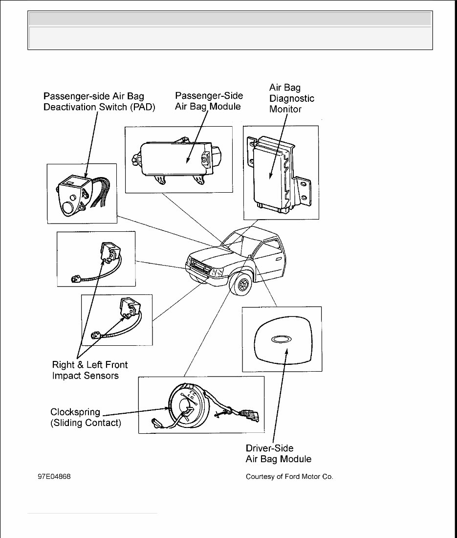
AIR BAG RESTRAINT SYSTEM (F150 & F250 LD) 1997 ACCESSORIES/SAFETY EQUIPMENT Ford Motor Co. - Air Bag Restraint System IDENTIFICATION Vehicle is equipped with driver-side air bag which is identified by a letter "L" in fourth position of Vehicle Identification Number (VIN). VIN is located on top of instrument panel, near lower left corner of windshield. VIN is also stamped on Vehicle Certification (VC) label, mounted on left front door pillar. The words Supplemental Restraint System (SRS) are embossed on steering wheel center hub. A label denoting that vehicle is equipped with air bag is affixed to driver-side sun visor. DESCRIPTION & OPERATION The Supplemental Restraint System (SRS) is designed to provide increased accident protection for driver and passenger by deploying air bags in a front-end collision. The air bags, stored in center of steering wheel and in instrument panel above glove box, deploy in about 40 milliseconds after impact sensors close. SRS is designed to be used with 3-point safety belts. During a front-end collision of sufficient force, both a front impact sensor and a safing sensor will activate simultaneously to inflate air bag. When a front impact sensor and safing sensor are closed at same time, electrical current will flow, igniting the driver-side and passenger-side air bag module. SRS includes following components: diagnostic monitor, driver-side air bag module, passenger-side air bag module and deactivation switch, SRS readiness light (AIR BAG warning light), front impact sensor and safing sensor, ignitor assemblies (in air bag modules), clockspring and associated wiring harnesses. See Fig. 1 . WARNING: To avoid injury from accidental air bag deployment, read and carefully follow all WARNINGS and SERVICE PRECAUTIONS . 1997 Ford Pickup F350 AIR BAG RESTRAINT SYSTEM (F150 & F250 LD) 1997 ACCESSORIES/SAFETY EQUIPMENT Ford Motor Co. - Air Bag Restraint System 1997 Ford Pickup F350 AIR BAG RESTRAINT SYSTEM (F150 & F250 LD) 1997 ACCESSORIES/SAFETY EQUIPMENT Ford Motor Co. - Air Bag Restraint System
Fig. 1: Locating SRS Components Courtesy of FORD MOTOR CO. 1997 Ford Pickup F350 AIR BAG RESTRAINT SYSTEM (F150 & F250 LD) 1997 ACCESSORIES/SAFETY EQUIPMENT Ford Motor Co. - Air Bag Restraint System
BACK-UP POWER SUPPLY A back-up power supply is used on all models and is located inside diagnostic monitor. If battery or battery cables are damaged in a collision before front impact sensors close circuit, back-up power supply will deploy air bag. Back-up power supply will hold a deployment charge for approximately one minute after positive battery cable is disconnected. CLOCKSPRING The steering column contains a clockspring to transfer electrical signals from steering column wiring harness to driver-side air bag module. Clockspring is mounted to steering column behind steering wheel. DIAGNOSTIC MONITOR The diagnostic monitor (located on left side of steering column underneath instrument panel) contains a microcomputer, which monitors electrical system components and connections. Diagnostic monitor performs a system self-check of SRS internal circuits every time ignition switch is turned to RUN position. Monitor also energizes SRS readiness indicator light (AIR BAG warning light) during initial system self-check and whenever a fault is detected. Faults are translated into flash codes and are displayed through AIR BAG warning light. If a system fault exists and/or AIR BAG warning light is malfunctioning, an audible tone will sound, indicating need for service. See TONE GENERATOR . Diagnostic monitor can also disarm SRS if certain faults occur. The air bag diagnostic monitor does not deploy air bags in the event of a collision. The right or left front impact sensors and safing sensor determine air bag deployment. The safing sensor is internal to air bag diagnostic monitor and is not replaced separately. DRIVER-SIDE AIR BAG MODULE The driver-side air bag module is mounted on center of steering wheel, covered by steering wheel trim cover. When a front impact sensor and safing sensor close, signaling an impact, ignitor triggers inflator. During ignition, sodium azide reacts with copper oxide, producing nitrogen gas, which inflates air bag. When air bag deploys, tear-seams molded into steering wheel trim cover separate, allowing inflation of air bag assembly. Driver-side air bag module is not serviceable and must be replaced as a complete assembly. PASSENGER-SIDE AIR BAG MODULE The passenger-side air bag module is mounted in right side of instrument panel, above glove box. When a front impact sensor and safing sensor close, signaling an impact, air bag igniters trigger inflator. Since passenger-side air bag is larger than driver-side air bag, inflator contains more gas generant in a different configuration to produce more gas. When air bag is activated, instrument panel trim cover tears at seams and hinges, allowing inflation. Passenger-side air bag module is only serviced as a complete assembly. PASSENGER-SIDE AIR BAG DEACTIVATION SWITCH 1997 Ford Pickup F350 AIR BAG RESTRAINT SYSTEM (F150 & F250 LD) 1997 ACCESSORIES/SAFETY EQUIPMENT Ford Motor Co. - Air Bag Restraint System
The Passenger-side Air bag Deactivation (PAD) switch is located on center instrument panel, below climate control vent, and contains a light diode (LED) that indicates when PAD switch is activated. This switch allows the passenger-side air bag deployment circuit to be disabled by inserting ignition key into PAD switch lock cylinder and turning key. It should be used whenever child safety seat is being used in front passenger-side seating position. ELECTRICAL SYSTEM SRS is powered directly from battery and can function with ignition switch in any position, including OFF and LOCK. System can also function when driver-side seat is unoccupied. The 3 main functions performed by electrical subsystem are: detecting an impact, switching electric power to igniters for air bag, and monitoring readiness of SRS. FRONT IMPACT SENSORS Front impact sensors are located at right and left sides of radiator support. Each impact sensor reacts to impacts according to direction and force. It discriminates between impacts that require air bag inflation and impacts that do not. When an impact occurs requiring air bag inflation, impact sensor contacts close, completing electrical circuit necessary for system operation. At least 2 sensors, safing sensor and one front impact sensor, must be activated simultaneously to inflate air bag. TONE GENERATOR AIR BAG warning light is prime means of determining SRS condition; however, a series of 5 audible tones, indicating that system requires servicing, will sound if AIR BAG warning light is out, and a fault occurs in system. Unless serviced, SRS may not function properly in an accident. Tone generator is located within diagnostic monitor. SYSTEM OPERATION CHECK 1. When checking SRS operation, and upon completion of each diagnostic test, check for faults in SRS. To check system, turn ignition switch to RUN position. If AIR BAG warning light illuminates for 4-8 seconds and then goes out, SRS is functioning properly and no fault codes exist. 2. If a fault code is detected in SRS during initial system check, AIR BAG warning light will either fail to light, stay on continuously, or flash a code sequence. If AIR BAG warning light flashes, indicating a fault in system, count number of flashes after fault code has cycled twice. Number of flashes represents a code number used to diagnose SRS. See DIAGNOSIS & TESTING . 3. If a system fault exists and AIR BAG warning light fails to light, an audible tone will be heard, indicating AIR BAG warning light is out and service is required. See TONE GENERATOR under DESCRIPTION & OPERATION. SERVICE PRECAUTIONS These precautions should be observed when working with SRS: 1997 Ford Pickup F350 AIR BAG RESTRAINT SYSTEM (F150 & F250 LD) 1997 ACCESSORIES/SAFETY EQUIPMENT Ford Motor Co. - Air Bag Restraint System
Disable SRS before servicing any SRS or steering column components. Failure to do so may result in accidental air bag deployment and personal injury. See procedures under DISABLING & ACTIVATING AIR BAG SYSTEM . Wait one minute after disabling SRS before working on vehicle. Back-up power supply holds a deployment charge for approximately one minute after positive battery cable is disconnected. Servicing SRS before one minute may cause accidental air bag deployment and possible personal injury. Because of critical system operating requirements, DO NOT service impact sensors, clockspring, diagnostic monitor or air bag module. Repairs are made by replacement only. Always wear safety glasses whenever servicing an air bag equipped vehicle or handling an air bag. When carrying a live air bag module, ensure air bag module and trim cover are pointed away from your body. This minimizes chance of injury in event of an accidental deployment. When placing a live air bag module on a bench or other surface, always face air bag module and trim cover facing up and away from surface. This will reduce motion of module if it is accidentally deployed. After deployment, air bag surface may contain deposits of sodium hydroxide, which may irritate skin. Sodium hydroxide is a product of gas generant combustion. Always wear gloves and safety glasses when handling a deployed air bag. Wash your hands using mild soap and water. Follow correct disposal procedures. See DISPOSAL PROCEDURES . If scrapping a vehicle with an undeployed air bag module, air bag must be deployed. See DISPOSAL PROCEDURES . If a part is replaced and new part does not correct condition, reinstall original part and perform diagnostic procedure again. Never probe connectors on air bag module. Doing so may cause air bag deployment and/or personal injury. Instruction to disconnect always refers to connector. DO NOT remove component from vehicle if instructed to disconnect. After any servicing, ensure AIR BAG warning light does not indicate any fault codes. See SYSTEM OPERATION CHECK . Replace air bag module if trim cover (deployment doors) is marred or damaged. DO NOT repaint trim cover. Paint may degrade cover material. Replace air bag module as necessary. See PROCEDURE 1 under SCRAPPED VEHICLE under DISPOSAL PROCEDURES. DISABLING & ACTIVATING AIR BAG SYSTEM WARNING: Wait one minute after disabling SRS before working on vehicle. Back-up power supply holds a deployment charge for approximately one minute after positive battery cable is disconnected. Servicing SRS before one minute may cause accidental air bag deployment and possible personal injury. CAUTION: When battery is disconnected, vehicle computer and memory systems may lose memory data. Driveability problems may exist until computer systems have completed a relearn cycle. See COMPUTER RELEARN PROCEDURES in GENERAL INFORMATION before DISCONNECTING 1997 Ford Pickup F350 AIR BAG RESTRAINT SYSTEM (F150 & F250 LD) 1997 ACCESSORIES/SAFETY EQUIPMENT Ford Motor Co. - Air Bag Restraint System
This 1997 Ford F-350 Service & Repair Manual provides comprehensive information needed to perform repairs, locate parts, and carry out routine maintenance on your vehicle. It includes detailed guidance on:
General Information
Routine Maintenance
Engine Removal and Installation
Fuel System
Lubrication and Cooling System
Engine Specifications
Transmission, Drive Chain & Sprockets
Steering System
Shocks
Body Work
Intake & Exhaust
Electrical System
Advanced Troubleshooting
And more!
With our downloadable repair manual, simply locate the page relevant to your task, print it, and get working on your 1997 Ford F-350. No more struggling with worn-out paper manuals covered in grease and dirt.
Whether you're on the trail or at the work site with just your smartphone, instantly access the information you need to diagnose and repair your truck without delay.
Each manual comes with a Lifetime Protection Policy. If it is lost or damaged, simply contact customer support and we will replace it free of charge, for life.
We offer various electronic repair service manuals, workshop manuals, owner's manuals, parts catalogs, and more – ensuring you have the detailed, technical information for your 1997 Ford F-350, as well as for many other vehicles and equipment.
INSTANT ACCESS
NO SHIPPING COST
GET A MANUAL SO NO WAITING, REPAIR IT NOW
If you are looking for a specific manual and cannot find it or do not see it listed, please contact our customer support team via the contact link above with details of the required manual, and we will do our best to list it for you.