


1999 ACCESSORIES & EQUIPMENT
Cruise Control Systems - F250-F550 Super Duty Pickups
DESCRIPTION
Cruise control system consists of speed control switches (ON, OFF, SET/ACCEL, COAST and RESUME),
speed control servo/actuator assembly, brake pedal position switch, clutch pedal position switch, deactivator
switch (brake pressure switch) and related wiring.
OPERATION
ENGAGING & DISENGAGING SYSTEM
System is operational at speeds greater than 30 MPH. When ON and SET/ACCEL switches have been pressed,
vehicle speed will be maintained until new speed is set, brake or clutch pedal is depressed, or OFF switch is
pressed. To increase or decrease set speed, hold SET/ACCEL or COAST switch until desired speed is reached,
then release switch. Tap SET/ACCEL or COAST switch for one MPH incremental increase or decrease in
speed.
ADJUSTMENTS
ACTUATOR CABLE
Adjustment procedure not available from manufacturer. If there is a problem with high idle due to not enough
NOTE: This article includes Cab & Chassis.
WARNING: Vehicles are equipped with air bag supplemental restraint system. Before
attempting any repairs involving steering column, instrument panel or
related components, see SERVICE PRECAUTIONS and DISABLING &
ACTIVATING AIR BAG SYSTEM in FORD MOTOR CO. - AIR BAG
RESTRAINT SYSTEMS article.
CAUTION: When battery is disconnected, vehicle computer and memory systems
may lose memory data. Driveability problems may exist until computer
systems have completed a relearn cycle. See COMPUTER RELEARN
PROCEDURES -- FORD MOTOR CO. article in GENERAL INFORMATION
before disconnecting battery.
NOTE: On 7.3L diesel, all speed control functions are controlled by the Powertrain
Control Module (PCM). See SELF - DIAGNOSTICS -- 7.3L DIESEL article in
ENGINE PERFORMANCE for diagnostic procedures. For diesel engine cruise
control system wiring diagrams, see WIRING DIAGRAMS .
length in actuator cable, check for proper cable installation. See ACTUATOR CABLE under REMOVAL &
INSTALLATION.
TROUBLE SHOOTING
Perform complete visual inspection of system. Repair as necessary. Ensure speedometer and horn are operating
properly. If there are any problems with speedometer or horn, repair those first. See appropriate ANALOG
INSTRUMENT PANELS article and/or STEERING COLUMN SWITCHES article. If Malfunction Indicator
Light (MIL) is lit or flashes, check Powertrain Control Module (PCM) for stored Diagnostic Trouble Codes
(DTCs). See appropriate SELF-DIAGNOSTICS article in ENGINE PERFORMANCE for diagnostic
procedures.
SYSTEM TESTS
SPEED CONTROL SERVO/ACTUATOR ASSEMBLY CONNECTOR TERMINAL
IDENTIFICATION
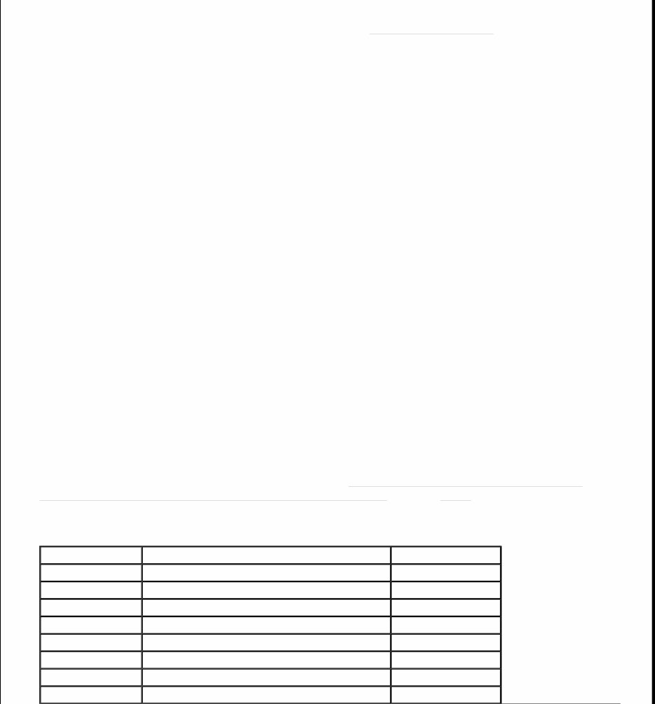
The following test procedures reference various terminals on speed control servo/actuator assembly connector.
For terminal number, circuit description and wire color, see SPEED CONTROL SERVO/ACTUATOR
ASSEMBLY CONNECTOR TERMINAL IDENTIFICATION table. See Fig. 1 .
SPEED CONTROL SERVO/ACTUATOR ASSEMBLY CONNECTOR TERMINAL
IDENTIFICATION
WARNING: Deactivate air bag system before performing any service operation
involving steering column components. See appropriate AIR BAG
RESTRAINT SYSTEMS article. Do not apply electrical power to any
component on steering column without first deactivating air bag system.
Air bag may deploy.
CAUTION: When battery is disconnected, vehicle computer and memory systems
may lose memory data. Driveability problems may exist until computer
systems have completed a relearn cycle. See COMPUTER RELEARN
PROCEDURES article in GENERAL INFORMATION before disconnecting
battery.
Terminal No. Circuit Description Wire Color
1 Not Used Not Used
2 Not Used Not Used
3 Vehicle Speed Input GRY/BLK
4 Brake/Clutch Position Switch Input TAN/LT BLU
5 Speed Control Switch Input LT BLU/BLK
6 Speed Control Switch Return DK GRN/ORG
7 Vehicle Power LT BLU/PNK
8 Not Used Not Used
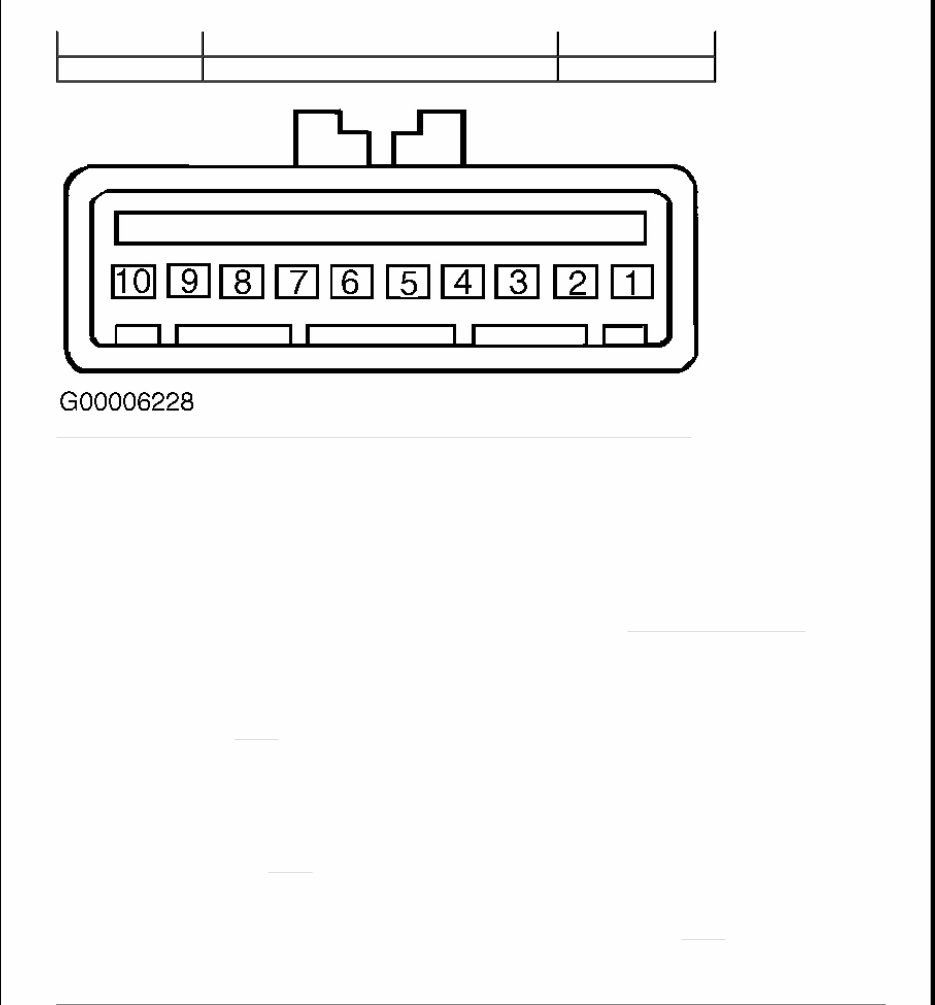
Fig. 1: Identifying Speed Control Servo/Actuator Assembly Connector Terminals
SPEED CONTROL INOPERATIVE
1. Turn ignition switch to LOCK position. Remove accelerator control splash shield. Inspect speed control
actuator cable attachment. Pull on actuator cable and note throttle movement. If actuator cable is okay, go
to next step. If cable is not okay, reattach or replace actuator cable. See ACTUATOR CABLE under
REMOVAL & INSTALLATION.
2. Disconnect speed control servo/actuator assembly 10-pin connector located at right side of engine
compartment near starter motor relay. Turn ignition switch to RUN position. Measure voltage between
speed control servo/actuator assembly connector terminals No. 7 (Light Blue/Pink wire) and No. 10
(Black wire). See Fig. 1 . If battery voltage does not exist, go to next step. If battery voltage exists, go to
step 5 .
3. Turn ignition switch to LOCK position. Check fuse junction panel fuse No. 28 (10-amp). If fuse is okay,
go to next step. If fuse is blown, replace fuse. Test system. If fuse blows again, repair short to ground in
Light Blue/Pink wire.
4. Measure resistance between speed control servo/actuator assembly connector terminal No. 10 (Black
wire) and ground. See Fig. 1 . If resistance is less than 5 ohms, repair open in Light Blue/Pink wire. If
resistance is 5 ohms or more, repair open in Black wire.
5. Turn ignition switch to LOCK position. Measure voltage between speed control servo/actuator assembly
connector terminals No. 4 (Tan/Light Blue wire) and No. 10 (Black wire). See Fig. 1 . If battery voltage
exists, replace brake pedal position switch. If battery voltage does not exist, go to next step.
6. Measure resistance between speed control servo/actuator assembly connector terminals No. 4 (Tan/Light
Blue wire) and No. 10 (Black wire). If resistance is less than 5 ohms, go to next step. If resistance is 5
9 Brake Pressure Input BLK/YEL
10 Ground BLK
NOTE: Ensure horn operates properly before performing this test. Repair as necessary.
See WIRING DIAGRAMS in appropriate STEERING COLUMN SWITCHES article.

ohms or more, go to step 16 .
7. Measure voltage between speed control servo/actuator assembly connector terminals No. 9 (Black/Yellow
wire) and No. 10 (Black wire). If battery voltage exists, go to step 10 . If battery voltage does not exist,
go to next step.
8. Disconnect deactivator switch (brake pressure switch) 2-pin connector located at brake master cylinder.
Measure resistance between switch terminals. If resistance is less than 5 ohms, go to next step. If
resistance is 5 ohms or more, replace switch.
9. Measure voltage between deactivator switch connector Light Green/Red wire terminal and ground. If
battery voltage exists, repair open in Black/Yellow wire. If battery voltage does not exist, repair open in
Light Green/Red wire. See WIRING DIAGRAMS .
10. Measure voltage between speed control servo/actuator assembly connector terminals No. 5 (Light
Blue/Black wire) and No. 10 (Black wire). See Fig. 1 . If battery voltage exists, go to step 17 . If battery
voltage does not exist, go to next step.
11. Measure voltage between speed control servo/actuator assembly harness connector terminals No. 5 (Light
Blue/Black wire) and No. 10 (Black wire) while pressing speed control actuator ON switch. If battery
voltage exists, go to step 14 . If battery voltage does not exist, go to next step.
12. Disconnect speed control/horn switch assembly 6-pin connector in steering wheel. Measure resistance in
Light Blue/Black wire between speed control servo/actuator assembly connector terminal No. 5 and speed
control/horn switch assembly connector terminal No. 1. See Fig. 1 and Fig. 2 . If resistance is less than 5
ohms, go to next step. If resistance is 5 ohms or more, repair open in Light Blue/Black wire.
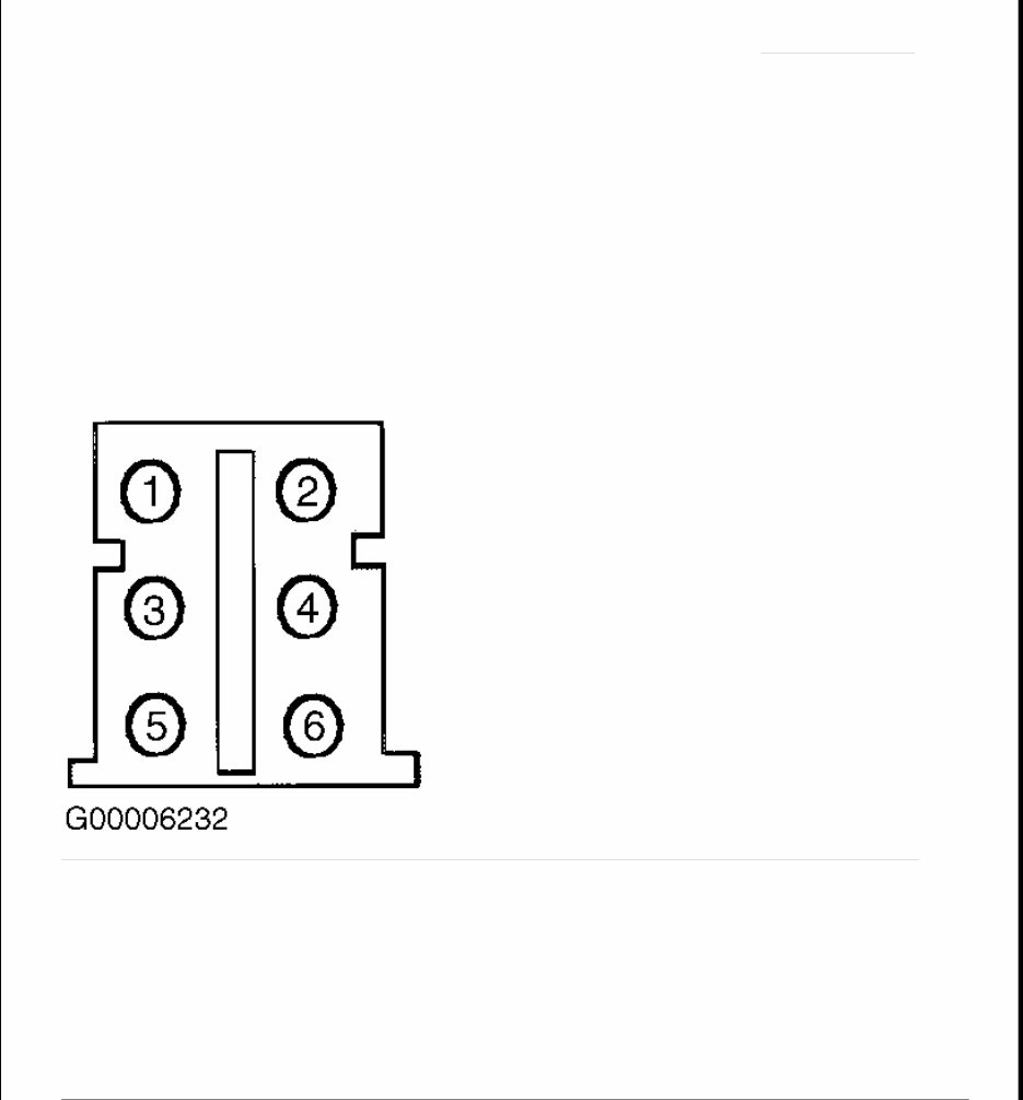
13. Remove driver's air bag. See appropriate AIR BAG RESTRAINT article. Disconnect speed control
switches connector. Measure resistance between speed control/horn clockspring connector terminal No. 1
and top of speed control/horn clockspring terminal No. 5. See Fig. 3 . If resistance is less than one ohm,
replace speed control actuator switch. See SPEED CONTROL SWITCHES under REMOVAL &
INSTALLATION. If resistance is one ohm or more, replace speed control/horn clockspring. See
CLOCKSPRING under REMOVAL & INSTALLATION.
14. With SET/ACCEL switch pressed, measure resistance between speed control servo/actuator assembly
connector terminals No. 5 (Light Blue/Black wire) and No. 6 (Dark Green/Orange wire). See Fig. 1 . If
resistance is 612-748 ohms, go to next step. If resistance is not 612-748 ohms, replace speed control
actuator switch. See SPEED CONTROL SWITCHES under REMOVAL & INSTALLATION.
15. Drive vehicle and observe speedometer. If speedometer operates properly, repair open in Gray/Black
wire. See WIRING DIAGRAMS . If speedometer does not operate properly, repair speedometer as
necessary. See appropriate ANALOG INSTRUMENT PANELS article for diagnostic procedures.
16. Disconnect Brake Pedal Position (BPP) switch 5-pin connector. Measure resistance between BPP switch
connector Pink/Orange wire terminal and ground. If resistance is less than 5 ohms, go to step 19 . If
resistance is 5 ohms or more, repair open in Pink/Orange wire.
17. Turn ignition switch to LOCK position. Disconnect speed control/horn switch assembly 6-pin connector.
Turn ignition switch to RUN position. Measure voltage between speed control servo/actuator assembly
connector terminals No. 5 (Light Blue/Black wire) and No. 10 (Black wire). See Fig. 1 . If battery voltage
exists, go to next step. If battery voltage does not exist, replace speed control actuator switches. See
SPEED CONTROL SWITCHES under REMOVAL & INSTALLATION.
18. Turn ignition switch to LOCK position. Disconnect speed control/horn switch assembly 6-pin connector.
Turn ignition switch to RUN position. Measure voltage between speed control servo/actuator assembly
connector terminals No. 5 (Light Blue/Black wire) and No. 10 (Black wire). If voltage exists, repair short
to power in Light Blue/Black wire. If no voltage exists, replace clockspring. See CLOCKSPRING under
REMOVAL & INSTALLATION.
19. Turn ignition switch to RUN position. Measure voltage between BPP switch connector Light Blue/Black
wire terminal and ground. If battery voltage exists, go to next step. If battery voltage does not exist, repair
open in Light Blue/Black wire.
20. Disconnect Clutch Pedal Position (CPP) switch (M/T) or jumper (A/T) 6-pin connector. Measure
resistance of Red/Light Green wire between BPP switch connector and CPP switch (jumper on A/T)
connector. If resistance is less than 5 ohms, go to next step. If resistance is 5 ohms or more, repair open in
Red/Light Green wire.
21. Measure resistance of Tan/Light Blue wire between CPP switch (jumper on A/T) connector and speed
control servo/actuator assembly connector terminal No. 4. If resistance is less than 5 ohms, go to next
step. If resistance is 5 ohms or more, repair open in Tan/Light Blue wire.
22. Measure resistance between CPP switch (jumper on A/T) terminals No. 3 and 4 (center terminals). If
resistance is less than 5 ohms, replace BPP switch. If resistance is 5 ohms or more, replace CPP switch or
jumper.
Fig. 2: Identifying Speed Control/Horn Switch Assembly Connector Terminals (Female Side Shown)
Courtesy of FORD MOTOR CO.
You're Reading a Preview
What's Included?
Fast Download Speeds
Offline Viewing
Access Contents & Bookmarks
Full Search Facility
Print one or all pages of your manual
$41.99
2010 Ford F-250 Super Duty Service & Repair Manual
Viewed 95 Times Today

What's Included?
Fast Download Speeds
Offline Viewing
Access Contents & Bookmarks
Full Search Facility
Print one or all pages of your manual
$41.99

Secure transaction
What's Included?
Fast Download Speeds
Offline Viewing
Access Contents & Bookmarks
Full Search Facility
Print one or all pages of your manual
2010 Ford F-250 Super Duty Service & Repair Manual
This comprehensive manual for the 2010 Ford F250 Super Duty provides all the necessary information for repairing, maintaining, rebuilding, refurbishing, or restoring your vehicle. It covers all diagnostic and repair procedures in great detail, making it useful for both professional technicians and DIY enthusiasts.
Service Manual Details:
- Printable: YES
- Requirements: PDF Reader
- File Type: PDF
- Compatibility: All Versions of Windows, Mac, and Linux
Table of Content (example):
- GENERAL INFORMATION
- ENGINE
- Engine Mechanical
- Engine Lubrication System
- Engine Cooling System
- Engine Control System
- Fuel System
- Exhaust System
- TRANSMISSION/TRANSAXLE
- Clutch
- Manual Transaxle
- Automatic Transaxle
- DRIVELINE/AXLE
- Front Axle
- Rear Axle
- SUSPENSION
- Front Suspension
- Rear Suspension
- Road Wheels & Tyres
- BRAKES
- Brake System
- Parking Brake System
- Brake Control System
- STEERING
- Power Steering System
- Steering System
- RESTRAINTS
- Seat Belts
- Supplemental Restraint System (SRS)
- BODY
- Body, Lock & Security System
- Glasses, Window System & Mirrors
- Roof
- Exterior & Interior
- Instrumental Panel
- Seat
- AIR CONDITIONER
- Air Conditioner System
- ELECTRICAL
- Wiring Diagrams
- Starting & Charging System
- Lighting System
- Driver Information System
- Wiper, Washer & Horn
- Body Control System
- Lan System
- Audio Visual, Navigation & Telephone System
- Auto Cruise Control System
- Power Supply, Ground & Circuit Elements
- MAINTENANCE
- Maintenance
- INDEX
- Alphabetical Index
This manual is a valuable resource for anyone looking to perform maintenance or repairs on the 2010 Ford F250 Super Duty.


