

2004-2008 Ford F-150 Service & Repair Manual
What's Included?
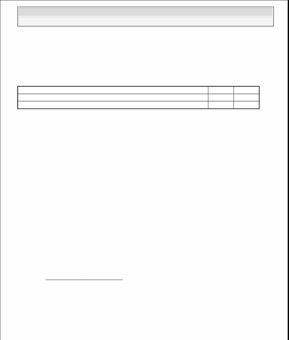
Fast Download Speeds
Offline Viewing
Access Contents & Bookmarks
Full Search Facility
Print one or all pages of your manual
2008 ENGINE PERFORMANCE
Acceleration Control - F-150 & Mark LT
SPECIFICATIONS
TORQUE SPECIFICATIONS
DESCRIPTION AND OPERATION
ACCELERATION CONTROL
The acceleration control consists of one of the following:
A fixed accelerator pedal and position sensor assembly
An adjustable accelerator pedal and position sensor assembly
The throttle is controlled by an accelerator pedal position (APP) sensor on the accelerator pedal assembly. The
APP sensor sends a signal to the PCM in response to throttle pedal movements initiated by the driver. The PCM
sends a signal to the electronic throttle control which increases and decreases throttle position.
Some vehicles are equipped with adjustable pedals. This allows both the accelerator and brake pedals to be
adjusted simultaneously forward or rearward. A rocker switch on the instrument panel provides adjustment on
the pedal assembly when it is activated. On vehicles with the memory seat option, the pedal position can be
controlled by the memory selection, as well as the rocker switch. The adjustable accelerator pedal can be
serviced separately from the adjuster. The components in the acceleration control system are not adjustable and
new components must be installed if damaged or worn.
DIAGNOSTIC TESTS
ACCELERATION CONTROL
Refer to the Introduction - Gasoline Engines article.
REMOVAL AND INSTALLATION
ACCELERATOR PEDAL - FIXED
Description Nm lb-ft
Adjustable accelerator pedal assembly bolts 25 18
Fixed accelerator pedal assembly bolts 25 18
2008 Lincoln Mark LT
2008 ENGINE PERFORMANCE Acceleration Control - F-150 & Mark LT
2008 Lincoln Mark LT
2008 ENGINE PERFORMANCE Acceleration Control - F-150 & Mark LT
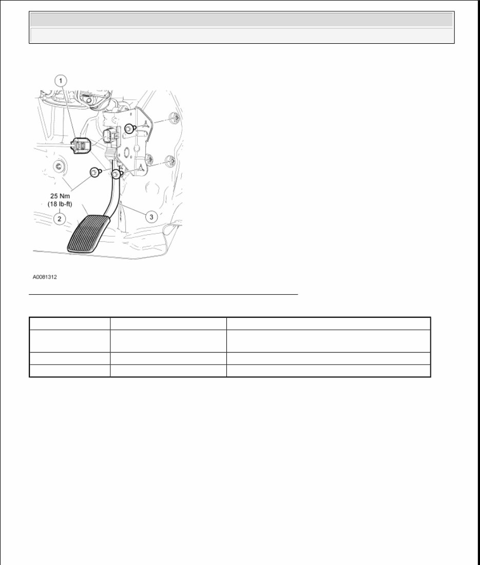
Fig. 1: View Of Accelerator Pedal Fixed With Torque Specification
Courtesy of FORD MOTOR CO.
REMOVAL AND INSTALLATION
1. Disconnect the accelerator pedal electrical connector.
2. Remove the 3 accelerator pedal assembly bolts and the accelerator pedal assembly.
To install, tighten to 25 Nm (18 lb-ft).
3. To install, reverse the removal procedure.
ACCELERATOR PEDAL - ADJUSTABLE
Item Part Number Description
1 - Accelerator pedal electrical connector (part of
12A581)
2 W709356 Accelerator pedal assembly bolt (3 required)
3 9F836 Accelerator pedal assembly
2008 Lincoln Mark LT
2008 ENGINE PERFORMANCE Acceleration Control - F-150 & Mark LT
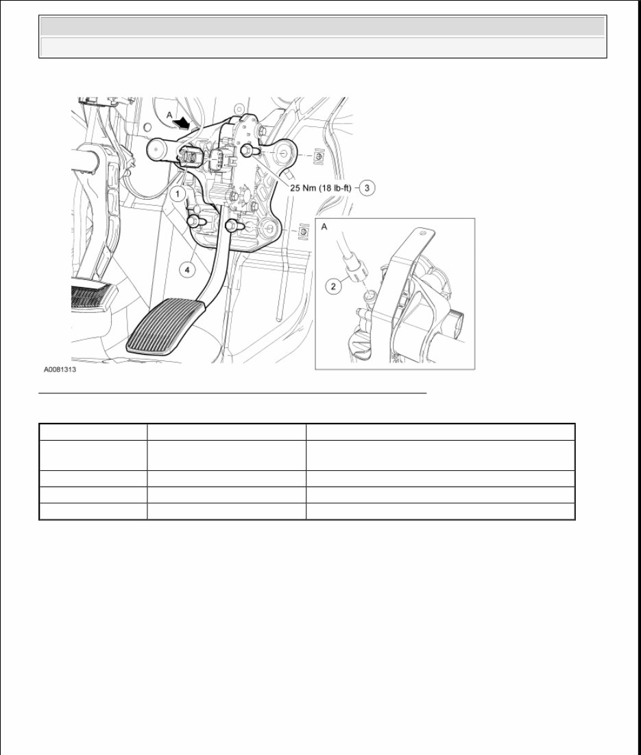
Fig. 2: View Of Accelerator Pedal Adjustable With Torque Specification
Courtesy of FORD MOTOR CO.
REMOVAL AND INSTALLATION
1. Disconnect the accelerator pedal electrical connector.
2. Disconnect the accelerator pedal assembly drive cable.
3. Remove the 3 accelerator pedal assembly bolts and the accelerator pedal assembly.
To install, tighten to 25 Nm (18 lb-ft).
4. To install, reverse the removal procedure.
Item Part Number Description
1 - Accelerator pedal electrical connector (part of
12A581)
2 G4250 Accelerator pedal assembly drive cable
3 W709356 Accelerator pedal assembly bolt (3 required)
4 G4211 Accelerator pedal assembly
NOTE: The brake pedal and the accelerator pedal must be in the same position when
installing a new cable or a new accelerator pedal. The pedals must be all the
way forward or all the way rearward.
2008 Lincoln Mark LT
2008 ENGINE PERFORMANCE Acceleration Control - F-150 & Mark LT
You're Reading a Preview
What's Included?
Fast Download Speeds
Offline Viewing
Access Contents & Bookmarks
Full Search Facility
Print one or all pages of your manual
$33.99
$44.99
Viewed 52 Times Today


Secure transaction
What's Included?
Fast Download Speeds
Offline Viewing
Access Contents & Bookmarks
Full Search Facility
Print one or all pages of your manual
$33.99
$44.99
2004-2008 Ford F-150 Service & Repair Manual
This comprehensive manual is essential for car repair and widely used by professional mechanics and DIY enthusiasts. It provides detailed views of parts with easy-to-print pages that eliminate the risk of grease marks. Covering the years 2004-2008, the manual offers over 5000 pages of in-depth information on various aspects of the Ford F-150.
The manual works on all computers, including PC and MAC, and covers a wide range of topics, such as:
- Engine overhaul and rebuilding
- Brake systems
- Sunroof operations
- Timing belt replacement and service procedures
- Trouble codes and diagnostics
- Wiring diagrams
- Engine performance enhancements
- Front end procedures and specifications
- Suspension systems
- Transmission details
- Air conditioning service and capacities
- Computer diagnostic codes and firing orders
- Factory maintenance schedules and charts
- Serpentine belt routings with diagrams
- Complete torque specifications
- U-joint and CV-joint service procedures
- Comprehensive repair procedures
- Hundreds of illustrations
All information is accessible as a .PDF file for convenient viewing and reference.


