2000-2003 Ford F150 Pickup Truck Workshop Repair Service Manual BEST - 620MB !
Have a question?Ask Us
What's Included?
Fast Download Speeds
Offline Viewing
Access Contents & Bookmarks
Full Search Facility
Print one or all pages of your manual

2003 STARTING & CHARGING SYSTEMS
Starters - F150 Pickup
DESCRIPTION
The starter motor is a permanent magnet, gear reduction, 12-volt DC motor, equipped with an integral solenoid.
Starting system consists of a starter motor, solenoid, battery, ignition switch, Digital Transmission Range
(DTR) sensor (A/T) or Clutch Pedal Position (CPP) switch (M/T), starter relay, and interconnecting cables and
wires.
COMPONENT LOCATIONS
COMPONENT LOCATIONS
ADJUSTMENTS
DIGITAL TRANSMISSION RANGE SENSOR
4R100 Transmission
1. Raise and support vehicle. Disconnect manual shift control cable. Disconnect Digital Transmission Range
(DTR) sensor harness connector. Remove manual control lever nut. Loosen DTR sensor bolts.
2. Manual shift lever must be in Neutral. Using Transmission Range Sensor Alignment Gauge (307-351),
align DTR sensor slots. See Fig. 2 . Tighten DTR sensor bolts. Tighten fasteners to specification. See
TORQUE SPECIFICATIONS . With manual lever in Neutral, connect shift lever control cable.
Connect DTR sensor harness connector.
Component Location
Battery Junction Box Left Side Of Engine Compartment
Central Junction Box Under Left Side Of Instrument Panel
Clutch Pedal Position Switch On Pedal Assembly Bracket
Clutch Pedal Position Jumper On Pedal Assembly Bracket
Digital Transmission Range Sensor Left Side Of Transmission
Inertia Fuel Shutoff Switch Behind Right Side Of Front Kick Panel
Starter Relay Right Rear Of Engine Compartment
NOTE: When battery is disconnected, vehicle computer and memory systems may lose
memory data. Driveability problems may exist until computer systems have
completed a relearn cycle. See COMPUTER RELEARN PROCEDURES article in
GENERAL INFORMATION before disconnecting battery.
NOTE: Transmission Range Sensor Alignment Gauge (307-351) is required for this
procedure. See Fig. 1 .
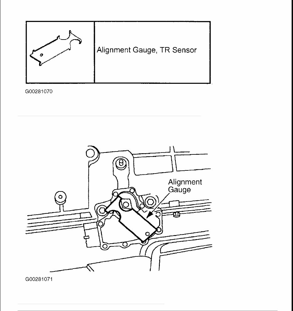
Fig. 1: Identifying Transmission Range Sensor Alignment Gauge (307 - 351)
Courtesy of FORD MOTOR CO.
Fig. 2: Aligning Digital Transmission Range Sensor (4R100)
Courtesy of FORD MOTOR CO.
4R70W Transmission
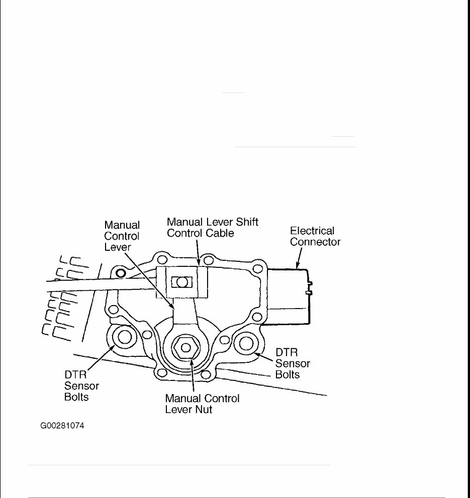
1. Disconnect the battery ground cable. Raise and support vehicle. Disconnect the Digital Transmission
Range (DTR) sensor electrical connector. See Fig. 3 . Do not pry on the swivel tube to disconnect the
transmission shift linkage. Disconnect the manual lever shift control cable. Remove the manual control
lever nut and discard. Remove the lever.
2. Loosen the DTR sensor bolts. Manual shift lever must be in the Neutral position. Using the Transmission
Range Sensor Alignment Gauge (307-351), align the DTR sensor slots. See Fig. 4 . The tool is designed
to fit snug. Tighten the bolts to specification. See TORQUE SPECIFICATIONS .
3. Install and position the manual control lever. Install a NEW manual lever shaft outer nut and torque to
specification. With the manual lever in overdrive connect the shift lever control cable. Install the DTR
sensor electrical connector. Lower the vehicle. Connect the battery ground cable.
Fig. 3: Identifying Digital Transmission Range Sensor Components (4R70W)
Courtesy of FORD MOTOR CO.
NOTE: When the battery is disconnect and reconnected, some abnormal drive
symptoms may occur while the vehicle relearns its adaptive strategy. The
vehicle may need to be driven 10 miles (16 km) or more to relearn the strategy.
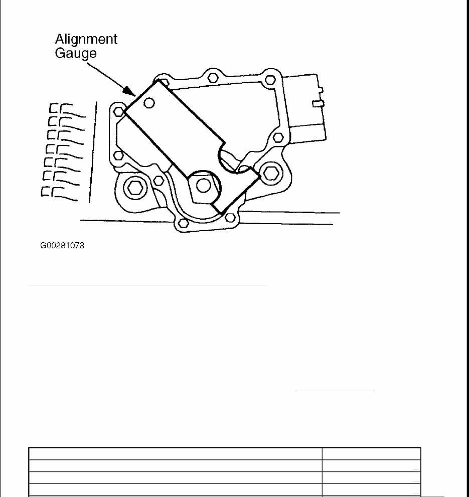
Fig. 4: Aligning Digital Transmission Range Sensor (4R70W)
Courtesy of FORD MOTOR CO.
TROUBLE SHOOTING
Verify customer compliant by operating starting system. Check battery for state of charge. Check cable
connections at battery and starter motor. Ensure transmission is fully engaged in Park or Neutral, or clutch pedal
is fully depressed. Check central junction box fuse No. 21 (15-amp). Check Gray fusible links, located at
positive battery cable. On models equipped with anti-theft system, ensure anti-theft system is operating
properly. See appropriate PASSIVE ANTI-THEFT SYSTEMS article in ACCESSORIES & EQUIPMENT for
additional information. If problem is not found, repair by symptom. See SYMPTOM INDEX table under
SYSTEM TESTS.
SYSTEM TESTS
SYMPTOM INDEX
Symptom Perform Test
Engine Does Not Crank & Relay Clicks A
Engine Does Not Crank & Relay Does Not Click B
Engine Cranks Slowly C
TEST A: ENGINE DOES NOT CRANK & RELAY CLICKS
1. Verify battery condition. If battery is okay, measure voltage between each Red wire at starter motor relay
and ground. Battery voltage should be present at one Red wire only. If battery voltage is present on one
Red wire, go to next step. If battery voltage is not present on either Red wire, repair or replace Red wire
between battery and starter motor relay cable. Check system operation.
2. Measure voltage between starter motor solenoid "B" terminal and ground. See Fig. 5 . If battery voltage is
present, go to next step. If battery voltage is not present, clean and tighten battery and solenoid terminal
connections. If battery voltage is still not present, replace positive battery cable. Check system operation.
3. Using jumper wire, connect one end to positive battery terminal and with other end, momentarily touch
starter solenoid "S" terminal. See Fig. 5 . If solenoid engages, go to next step. If solenoid does not
engage, replace starter motor. See STARTER MOTOR under REMOVAL & INSTALLATION. Check
system operation.
4. Using heavy gauge jumper wire, connect one end to positive battery terminal and with other end,
momentarily touch starter solenoid "M" terminal. See Fig. 5 . If starter spins, go to next step. If starter
does not spin, replace starter motor. See STARTER MOTOR under REMOVAL & INSTALLATION.
Check system operation.
5. Disconnect solenoid relay switch connectors. Disconnect starter motor solenoid connectors. Measure
resistance of Red wire between starter motor relay and starter solenoid. If resistance is less than 5 ohms,
replace starter motor relay. If resistance is 5 ohms or greater, repair or replace Red wire between starter
relay and starter solenoid. Check system operation.
Unusual Starter Noise D
Starter Spins But Does Not Crank Engine
(1)
(1)
Inspect starter motor mounting. Inspect flywheel ring gear and starter motor gear for damaged and
missing teeth. Repair or replace components as necessary.
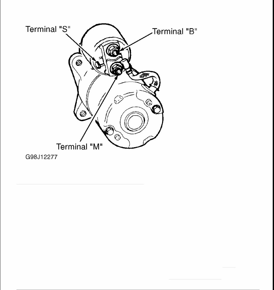
Fig. 5: Identifying Starter Solenoid Terminals (Typical)
Courtesy of FORD MOTOR CO.
TEST B: ENGINE DOES NOT CRANK & RELAY DOES NOT CLICK
1. Remove fuse No. 111 (40-amp) in battery junction box. Check continuity of fuse No. 111. If fuse No. 111
is okay, reinstall fuse and go to next step. If fuse No. 111 is open, install new fuse and go to step 15 .
2. Remove fuse No. 21 (15-amp) in central junction box. Check for continuity of fuse No. 21. If fuse No. 21
is okay, reinstall fuse and go to next step. If fuse No. 21 is open, install new fuse, and go to step 18 .
3. Measure voltage between ground and input side of central junction box fuse No. 21 while holding
ignition switch in START position. If battery voltage is present, go to step 6 . If battery voltage is not
present, go to next step.
4. Disconnect ignition switch 15-pin connector. Measure resistance in Red/Light Blue wire between input
side of central junction box fuse No. 21 and ignition switch connector terminal STA. See Fig. 6 . If
resistance is less than 5 ohms, go to next step. If resistance is 5 ohms or greater, repair open in Red/Light
Blue wire between ignition switch and central junction box. See WIRING DIAGRAMS . Check system
operation.
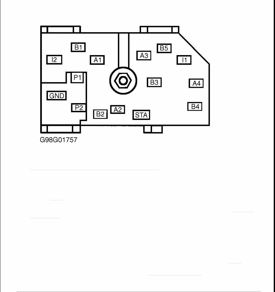
Fig. 6: Identifying Ignition Switch Connector Terminals
Courtesy of FORD MOTOR CO.
5. Remove battery junction box fuse No. 111 (40-amp). Measure resistance of Light Green/Violet wire
between ignition switch harness connector terminal B5 and output side of battery junction box fuse No.
111. See Fig. 6 . If resistance is less than 5 ohms, replace ignition switch. See appropriate STEERING
COLUMN SWITCHES article in ACCESSORIES & EQUIPMENT. If resistance is 5 ohms or greater,
repair open in Light Green/Violet wire between ignition switch and battery junction box. See WIRING
DIAGRAMS . Check system operation.
6. Turn ignition switch to LOCK position. Disconnect starter motor relay connector (Tan/Red wire).
Measure voltage between ground and Tan/Red wire at starter motor relay connector terminal while
holding ignition switch in START position. If battery voltage is present, replace starter motor relay.
Check system operation. If battery voltage is not present, go to next step (A/T models) or go to step 12
(M/T models).
7. Disconnect Digital Transmission Range (DTR) sensor 12-pin connector. Measure resistance of Tan/Red
wire between DTR sensor connector terminal No. 12 and starter motor relay connector. See Fig. 7 . If
resistance is less than 5 ohms, go to next step. If resistance is 5 ohms or greater, repair open in Tan/Red
wire between DTR sensor and starter motor relay. See WIRING DIAGRAMS . Check system operation.
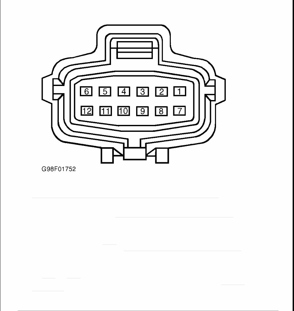
Fig. 7: Identifying Digital Transmission Range Sensor Connector Terminals
Courtesy of FORD MOTOR CO.
8. Check DTR sensor adjustment. See DIGITAL TRANSMISSION RANGE SENSOR under
ADJUSTMENTS. If DTR sensor is adjusted properly, go to next step. If DTR sensor is not adjusted
properly, adjust as necessary. Check system operation.
9. Connect a jumper wire between DTR sensor connector terminals No. 12 (Tan/Red wire) and No. 10
(Dark Blue/Orange wire). See Fig. 7 . Attempt to start vehicle. If vehicle does not start, go to next step. If
vehicle starts, replace DTR sensor. See DIGITAL TRANSMISSION RANGE SENSOR under
REMOVAL & INSTALLATION. Check system operation.
10. Disconnect Clutch Pedal Position (CPP) jumper 6-pin connector. Measure resistance of Dark
Blue/Orange wire between DTR connector terminal No. 10 and CPP jumper connector terminal No. 2.
See Fig. 7 and Fig. 8 . If resistance is less than 5 ohms, go to next step. If resistance is 5 ohms or greater,
repair open in Dark Blue/Orange wire between DTR sensor and CPP jumper. See WIRING
DIAGRAMS . Check system operation.
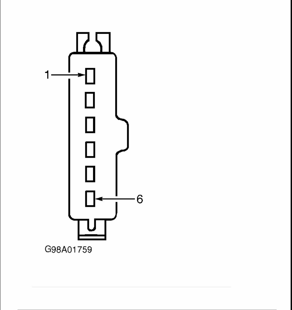
Fig. 8: Identifying Clutch Pedal Position Switch Or Jumper Connector Terminals
Courtesy of FORD MOTOR CO.
11. Measure resistance between CPP jumper terminals No. 1 and 2 (component side). If resistance is 5 ohms

or less, go to step 14 . If resistance is greater than 5 ohms, replace CPP jumper. Check system operation.
12. Disconnect starter motor relay connector (Tan/Red wire). Disconnect CPP switch 6-pin connector.
Measure resistance between Tan/Red wire at starter motor relay connector terminal and CPP switch
connector terminal No. 2 (Dark Blue/Orange wire). See Fig. 8 . If resistance is less than 5 ohms,
reconnect starter motor relay and go to next step. If resistance is 5 ohms or greater, repair open in
Tan/Red wire or Dark Blue/Orange wire between CPP switch and starter motor relay. See WIRING
DIAGRAMS . Check system operation.
13. Connect a jumper wire between CPP switch connector terminals No. 5 (White/Pink wire) and No. 6
(Gray/Yellow wire). Connect another jumper wire between CPP switch connector terminals No. 1
(White/Pink wire) and No. 2 (Dark Blue/Orange wire). See Fig. 8 . Attempt to start vehicle. If vehicle
does not start, go to next step. If vehicle starts, replace CPP switch. Check system operation.
14. Disconnect central junction box 34-pin connector C270b. Measure resistance of White/Pink wire between
central junction box connector C270b terminal No. 29 and CPP switch/jumper connector terminal No. 1.
See Fig. 8 and Fig. 9 . If resistance is less than 5 ohms, replace central junction box. If resistance is 5
ohms or greater, repair open in White/Pink wire between central junction box and CPP switch/jumper.
Check system operation.
You're Reading a Preview
What's Included?
Fast Download Speeds
Offline Viewing
Access Contents & Bookmarks
Full Search Facility
Print one or all pages of your manual
$41.99
Viewed 11 Times Today


Secure transaction
What's Included?
Fast Download Speeds
Offline Viewing
Access Contents & Bookmarks
Full Search Facility
Print one or all pages of your manual
$41.99
This comprehensive workshop repair service manual is specifically for the 2000-2003 Ford F150 Pickup Truck. It contains all the necessary information for repairing, maintaining, rebuilding, refurbishing, or restoring your vehicle. Whether you are a professional mechanic or a DIY enthusiast, this manual covers all diagnostic and repair procedures in great detail.
Key features of this manual include:
- Complete coverage of all repair procedures from A-Z
- High-quality photos, illustrations, and diagrams
- Compatibility with all versions of Windows, Mac, and Linux
The manual includes detailed information on the following:
- General Information
- Engine (mechanical, lubrication system, cooling system, control system, fuel system, exhaust system)
- Transmission/Transaxle (clutch, manual transaxle, automatic transaxle)
- Driveline/Axle (front axle, rear axle)
- Suspension (front suspension, rear suspension, road wheels & tires)
- Brakes (brake system, parking brake system, brake control system)
- Steering (power steering system, steering system)
- Restraints (seat belts, supplemental restraint system)
- Body (lock & security system, glass, window system & mirrors, roof, exterior & interior, instrumental panel, seat)
- Air Conditioner (air conditioner system)
- Electrical (wiring diagrams, starting & charging system, lighting system, driver information system, wiper, washer & horn, body control system, LAN system, audio visual, navigation & telephone system, auto cruise control system, power supply, ground & circuit elements)
- Maintenance
- Alphabetical Index
With this easy-to-use workshop repair manual, you can access and print the complete repair procedures without the need for advanced computer skills. Say goodbye to messy manuals that wear out over time. This manual is your go-to resource for all your repair and maintenance needs.