

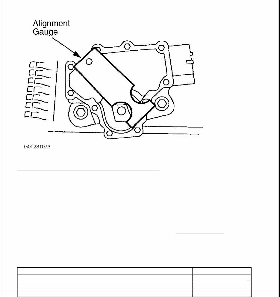
You're Reading a Preview
 Lifetime Access
2000-2003 Ford F-150 Service & Repair Manual
 Lifetime Access
 Lifetime Access
Description
2000-2003 Ford F-150 Service & Repair Manual
Engines Covered:
- 4.6L Triton V8
- 5.4L Triton V8
The 2000-2003 Ford F-150 Service & Repair Manual is a detailed technical repair reference for 10th-generation Ford F-150 pickup models equipped with the 4.6L Triton V8 and 5.4L Triton V8 engines. It covers general service procedures, scheduled maintenance, engine diagnostics, engine removal and installation, fuel and ignition systems, emissions diagnostics, transmission repair, driveline and axle service, brakes, steering, suspension, HVAC, electrical troubleshooting, wiring diagrams, body systems, restraint systems, OBD trouble codes, diagnostic charts, and technical service bulletins.
This manual is built for proper repair work, not basic owner-level information. It is useful for professional mechanics, Ford truck technicians, independent repair shops, fleet service teams, and novice DIYers who want the right service information before taking the truck apart. These F-150s are fairly straightforward trucks, but once you get into engine performance faults, transmission issues, electrical diagnostics, airbag testing, brake system faults, or driveline repairs, having the proper manual makes the work much easier to follow.
Whether you are servicing a 4.6L Triton, diagnosing a 5.4L running issue, checking OBD fault codes, repairing suspension wear, tracing an electrical fault, replacing brake components, or handling routine maintenance, this Ford F-150 repair manual gives you a structured workshop reference to work from.
What’s Inside the 2000-2003 Ford F-150 Service & Repair Manual
General Information, Service Procedures & Maintenance Guidelines
The manual includes complete general information, service procedures, maintenance guidelines, system overviews, specifications, and repair notes for 2000-2003 Ford F-150 models. These sections help set up the job properly before moving into engine, drivetrain, brake, suspension, electrical, or body repairs.
For a professional mechanic, this gives a quick reference for service data and repair order. For a DIY owner, it helps explain the truck’s systems before parts are removed, fluids are drained, or electrical components are tested.
Scheduled Maintenance & Service Intervals
Maintenance coverage includes scheduled service procedures, inspection points, service intervals, lubrication references, fluid checks, filter replacement, belt and hose inspection, brake checks, and general upkeep items. This section is useful for keeping the F-150 reliable as a daily driver, work truck, tow vehicle, or weekend hauler.
Older pickups respond well to regular maintenance. Engine oil, coolant, transmission fluid, differential oil, brakes, suspension parts, ignition components, and electrical connections all need attention as mileage and age build up.
4.6L & 5.4L Triton V8 Engine Repair
The engine section covers service and repair procedures for the 4.6L and 5.4L Triton V8 engines. Coverage includes diagnostics, removal, installation, disassembly, internal component inspection, mechanical repair, mounted components, and service procedures used during deeper engine work.
This section is useful when dealing with oil leaks, coolant leaks, compression concerns, engine noise, misfires, rough running, gasket replacement, or larger engine repairs. The Triton V8 engines are common, but correct service data and procedure still matter when the job goes beyond basic tune-up work.
Engine Performance Diagnostics & Troubleshooting
The manual includes engine performance diagnostics and troubleshooting for fuel, ignition, air intake, emissions, and electronic engine control systems. This helps with check engine lights, hesitation, poor idle, misfires, hard starting, weak power, poor fuel economy, and driveability complaints.
A fault code gives you a starting point, but it does not always name the failed part. The manual helps connect symptoms with proper testing, component checks, circuit inspection, and system verification.
Fuel System Service & Component Testing
Fuel system coverage includes fuel delivery, pressure testing, fuel system diagnostics, component servicing, and related repair procedures. This section is useful when working through hard starting, stalling, lean or rich running, poor throttle response, fuel pump concerns, injector issues, or fuel delivery faults.
Fuel problems can feel like ignition, sensor, or mechanical issues from the driver’s seat. Having the proper test procedure helps narrow the issue down before parts are replaced.
Ignition, Starting & Charging System Service
The manual includes service information for ignition components, starting system circuits, starter motor operation, alternator testing, battery checks, and electrical distribution. This section is useful for no-start problems, slow cranking, weak charging, misfires, ignition faults, battery drain, or charging warning symptoms.
Older trucks can develop weak grounds, corroded cables, worn connectors, failing alternators, or starter issues. The manual helps check the full circuit instead of blaming the first part that looks suspicious.
Emissions System & EVAP Diagnostics
Emissions coverage includes diagnostic and repair procedures for emission control systems, evaporative emissions components, sensors, and related engine management systems. This is useful when dealing with EVAP codes, oxygen sensor faults, catalyst-related issues, vacuum leaks, emissions inspection problems, or check engine light concerns.
Emissions faults can come from hoses, sensors, valves, wiring, leaks, or control system problems. The manual helps walk through the system properly before replacing parts.
Manual & Automatic Transmission Service
Transmission coverage includes manual and automatic transmission diagnostics, servicing, component repair, internal operation, and removal and installation information. This section is useful when dealing with hard shifting, slipping, delayed engagement, transmission leaks, gear noise, clutch-related symptoms, or shift quality problems.
Transmission issues can be mechanical, hydraulic, electrical, fluid-related, or linked to engine control inputs. The manual gives a more organized way to check the system before making larger repair decisions.
Driveline, Differential & Axle Repair
Driveline and axle coverage includes driveshafts, differential service, ring gear servicing, axle components, seals, bearings, and power delivery parts. This section is useful when diagnosing clunks, vibration, differential noise, leaks, worn joints, axle wear, or driveline service needs.
Pickup trucks put steady load through the drivetrain, especially when towing or hauling. Proper inspection helps catch worn joints, leaking seals, or noisy differential parts before the repair gets more involved.
Brake System Diagnostics, Inspection & Repair
Brake system coverage includes inspection, diagnostics, service, and repair procedures for brake components, hydraulic systems, parking brake parts, and safety-related braking systems. This section is useful for pad and rotor service, brake bleeding, soft pedal complaints, brake noise, pulling under braking, leaks, or warning lights.
Brake work on a truck needs to be handled properly, especially if it carries tools, cargo, or trailers. The manual gives the service information needed for both routine brake repairs and deeper troubleshooting.
Steering System Service & Alignment Procedures
The steering section includes diagnostics, inspection, adjustment, and repair information for steering components, linkage, steering gear, and handling-related systems. This section is useful for loose steering, wandering, steering noise, vibration, heavy steering, poor return-to-center, or alignment-related concerns.
Steering complaints can come from tires, suspension wear, alignment, axle parts, or steering components. The manual helps check those areas in a sensible order.
Front & Rear Suspension Service
Suspension coverage includes front and rear suspension components, inspection procedures, component replacement, alignment support, and ride handling diagnostics. This section is useful when dealing with clunks, uneven tire wear, poor ride quality, sagging, loose front-end feel, or worn bushings and joints.
These F-150s are old enough now that suspension wear is common. Shocks, bushings, ball joints, control arms, springs, and related hardware should be checked properly before replacing parts at random.
HVAC Heating & Air Conditioning Repair
HVAC coverage includes heating and air conditioning diagnostics, blower system service, climate control components, compressor-related checks, air distribution systems, and heater system repair. This section is useful for poor cooling, weak heat, blower faults, air direction problems, compressor concerns, or HVAC electrical faults.
HVAC repairs often involve both mechanical and electrical testing. The manual helps separate refrigerant-side problems, blower circuit issues, control faults, and air distribution concerns.
Automotive Electrical System Troubleshooting
The manual includes electrical troubleshooting for wiring, fuses, relays, connectors, switches, grounds, modules, sensors, lighting circuits, charging circuits, and vehicle electrical components. This is useful for no-start issues, lighting faults, accessory problems, warning indicators, battery drain, or intermittent electrical complaints.
Electrical faults on older trucks often come from vibration, corrosion, moisture, damaged wiring, weak grounds, or previous repairs. The manual gives the circuit information needed to trace the fault properly.
Wiring Diagrams & Electrical Schematics
The manual includes wiring diagrams and electrical schematics for accurate fault tracing. These references help with circuit testing, connector identification, power and ground checks, component location, and electrical system diagnosis.
When a truck has lighting issues, no-start complaints, accessory faults, or intermittent electrical problems, wiring diagrams are one of the most useful references to have beside you.
Body Systems, Accessories & Trim Components
Body and accessory coverage includes interior components, exterior components, trim, panels, doors, fittings, body hardware, and related service procedures. This section is useful when removing trim, repairing body components, servicing doors, replacing exterior parts, or accessing wiring behind panels.
Interior and exterior work is easier when you know where the fasteners, clips, brackets, and hidden mounting points are. The manual helps reduce broken trim and loose panels after reassembly.
Restraint System & Airbag Diagnostics
The restraint system section includes airbag diagnostics, testing procedures, occupant protection components, sensors, and related repair information. This section is useful when dealing with airbag warning lights, SRS faults, interior repairs near restraint components, or safety system diagnostics.
Airbag and restraint systems need careful handling. The manual helps outline the correct procedures and precautions before working around those components.
OBD Trouble Codes & Diagnostic Charts
The manual includes OBD trouble codes and diagnostic charts, covering Ford-specific and generic fault codes. These sections help with code reading, fault tracing, symptom-based diagnosis, system testing, and repair verification.
A code should guide the repair, not replace diagnosis. The manual helps connect the code to the right test path so the actual cause can be confirmed.
Technical Service Bulletins & Known Issue References
The manual includes access to technical service bulletins for known issues, repair updates, and factory service information where applicable. This is useful when a problem has a documented repair approach or updated diagnostic process.
TSBs can be helpful on older trucks because some faults are common enough to have known checks or service notes. That saves time during diagnosis and helps avoid repeating repairs that have already been figured out by the manufacturer.
Why Choose This Ford F-150 Service Manual?
The 2000-2003 Ford F-150 Service & Repair Manual gives you detailed technical service information for 10th-generation F-150 pickups equipped with 4.6L and 5.4L Triton V8 engines. It covers general service procedures, scheduled maintenance, engine repair, engine diagnostics, fuel and ignition systems, emissions controls, transmissions, driveline and axle service, brakes, steering, suspension, HVAC, electrical troubleshooting, wiring diagrams, body systems, restraint systems, OBD trouble codes, diagnostic charts, and technical service bulletins.
For professional mechanics and Ford truck technicians, it works as a practical workshop reference when checking procedures, specifications, and diagnostics. For novice DIYers, it gives a more organized way to understand the truck before removing parts. You still need proper tools, safe working habits, and care around fuel, electrical, brake, and restraint systems, but the manual gives you the repair path to follow.
This manual is especially useful for F-150 trucks that are now seeing age-related repairs. Common jobs can include engine sensor diagnostics, ignition issues, cooling system repairs, transmission service, brake work, suspension wear, driveline vibration, HVAC faults, body repairs, and electrical troubleshooting. A detailed repair manual helps keep those jobs tied to proper service information.
Format & Compatibility
This manual is supplied in digital PDF format, making it easy to view on a desktop, laptop, tablet, or phone. You can search for service procedures, engine systems, transmission sections, brake repairs, suspension components, OBD codes, wiring diagrams, specifications, and maintenance procedures without flipping through a printed binder.
The searchable PDF format is practical in the garage, workshop, or service truck because you can pull up the section you need, follow diagnostic charts, check service specs, zoom in on diagrams, and print selected pages for the job if needed.
Download the 2000-2003 Ford F-150 Service & Repair Manual
If you are maintaining, diagnosing, or repairing a 2000-2003 Ford F-150, this manual gives you the technical service information needed to approach the job properly. It covers 10th-generation F-150 pickups with 4.6L and 5.4L Triton V8 engines, along with engine repair, engine performance diagnostics, fuel system service, transmissions, driveline components, axles, brakes, steering, suspension, HVAC, electrical systems, body systems, restraint systems, OBD diagnostic charts, and technical service bulletins.
It is a practical reference for Ford technicians, independent repair shops, fleet mechanics, truck owners, and DIY F-150 owners who want detailed Ford F-150 service information in a searchable digital format.
Language: English
Compatibility: Windows, macOS, Linux, iOS, Android
Requirements: PDF Reader (e.g., Adobe Reader)


