2002 Ford Explorer Sport Trac Service & Repair Manual Software
What's Included?
Lifetime Access
Fast Download Speeds
Online & Offline Access
Access PDF Contents & Bookmarks
Full Search Facility
Print one or all pages of your manual
Mazda Navajo, Mercury Mountaineer & Repair by Jay Storer and John H Haynes Member of the Guild of Motoring Writers Models covered: All Ford Explorer» Mazda Navajo and Mercury Mountaineer models 1991 through 2001 Explorer Sport models through 2003, and Explorer Sport Trac models through 2005 (7H12 - 36024) ( 2021) MtrcsnGtivs ASSOCIATION MtlVBtU Haynes Publishing Group Sparkford Nr Yeov'f! Somerset BA22 7JJ England Haynes North America, Inc 861 Lawrence Drive Newbury Park California 91320 USA FGKU ■s :МГЙО POKS7-
is manual ^ThlpS p " * of ,Ws manua' iS r ,hel£ n„ oet the besl value from your vehicle. It IZ 2? s0 ^several ways. It can help you ^ h at work must be done, even if you declde ™s a dealer service d C r t ^ n r or a repair shop; it provides infor- S i and procedures for routine mainte nance and servicing; and « M diagnostic and repair procedures to follow when trouble 0CC!JWe hope you use the manual to tackle the work yourself* For many simpler jobs 1 doing it yourself may be quicker than arrang ing an appointment to get the vehicle jnto a shop and making the trips to reave it and pick it up. More importantly, a lot of money can be saved by avoiding the expense the shop must pass on to you to cover its labor and overhead costs. An added benefit is the sense of satisfaction and accomplishment that you fee! after doing the job yourself. Using the manual The manual is divided Into Chapters Each Chapter is divided into numbered Sec tions, which are headed in bold type between horizontal lines. Each Section consists of consecutively numbered paragraphs. At the beginning of each numbered Sec tion you will be referred to any illustrations which appfy to the procedures in that Sec tion, The reference numbers used In illustra tion captions pinpoint the pertinent Section and the Step within that Section. That is, illustration 3.2 means the illustration refers to Section 3 and Step (or paragraph) 2 within thal Section, ■ n v i r, Procedures, once are not normally repeated ,ri ^ W sary to refer to another Ch ®" ir* V ’ ence will be giVen as Cha ®pter. the r? " number. Cross references n a"d Ste*’ of the word "Chapter" J? ? " "“S and/or paragraphs in the здт! 1 ° “"«ft example, "see Section e* mT Cha^ ' F Chapter. mear>5in the References to the left r„ ve assume you are sitting 01 seat, facing forward. 'Э,n “» dr,Ver! Even though WB hau manual with extreme care rJSh WrM ,his -Sher nor the author can accep t the№ for any errors in. or omissions (nation given. • infor- NOTE A Note provides information necessary to properly complete a procedure or informatinn •„ cedure easier to understand, whrch will niake the pro- CAUTION A Caution provides a special procedure or special steps which must be taken „м и - , where the Caut.on is found. Not heeding a Caution can result in damage to the asse^b'ybeinj w a rk e d 'o 'r^ ^ WARNING ‘ A Warning provides a special procedure or special steps which must hs taL-оп ... m i , where the Warning is found. Not heeding a Warning can result in personal ,njury Complet,n9 « * Procedure Acknowledgements Writers who contributed to this project include Alan Ahlstrand and Jeff Kibler. ,992' ,993’ ,998' ,999- » " • 2W 5 A book in the Haynes Automotive Repair Manual Series Printed in the U.S.A. mechanical, including phdtacoov^n3 Ь° 01' be r0proeluced or transmitted in any form or by any means, electronic or ing from the copyright holder ^ recording or by any information storage or retrieval system, without permission in writ- ISBN 1 56392 591 5 c ~ Number; 2005931740 While every attempt is made to authors or publishers for F o н* ensure t,iat the information in this manual is correct, no liability can be accepted by the ----------------- ' dan>a9e or injury caused by any errors In, or omissions from, the Information given. _ of Haynes PubJtehino r & re9^tered trademarks of Ford Motor Company. Ford Motor Company is not a sponsor or — ---- ------------- ■ rouP 0r Haynes North America, inc. and is not a contributor to the content of this manual. 05*352
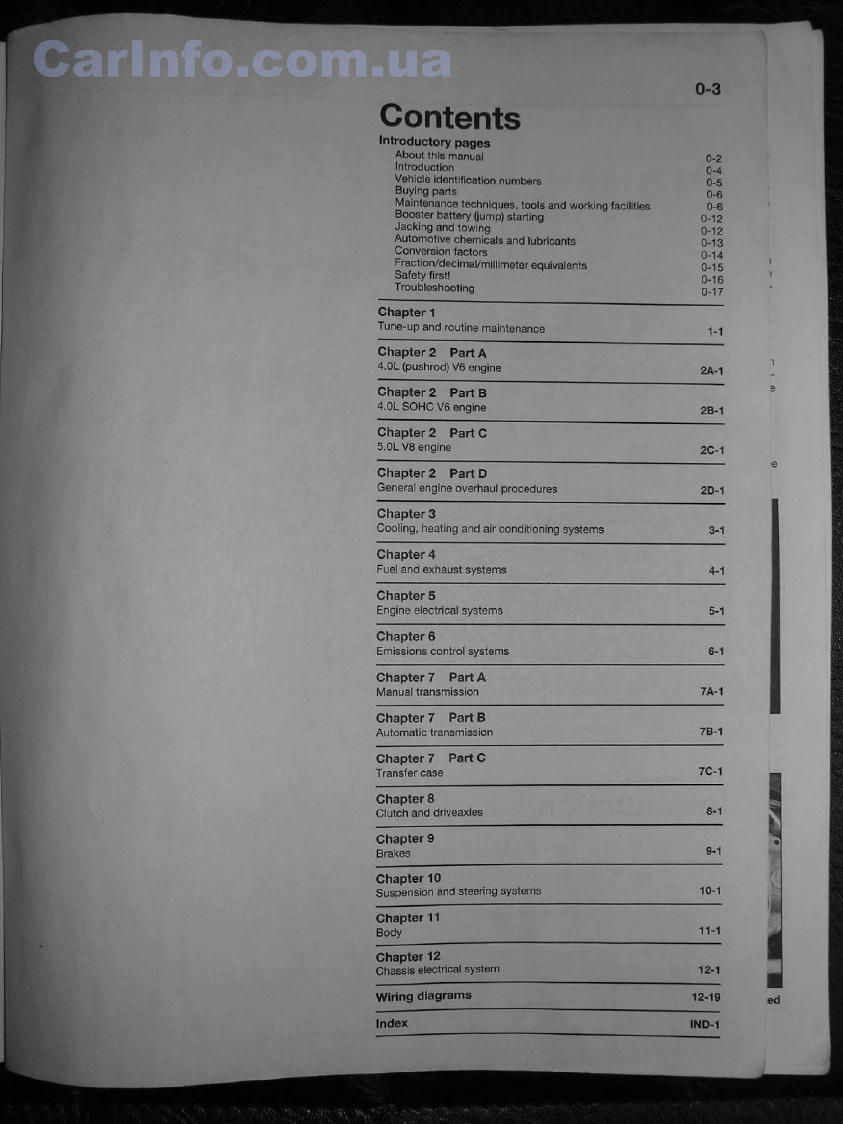
arInfo.com.ua ntents Introductory pages About this manual Introduction Vehicle identification numbers Buying parls Maintenance techniques, tools and working facilities Booster battery (jump) starting Jacking and towing Automotive chemicals and lubricants Conversion factors F raction/d 0 c imal/m iIIimete г equiva I en ts Safety first! Troubleshooting 0-3 о-г Q-A 0-5 0-6 0 6 0-12 0-15 0-13 Q ’ 14 0-15 0-1 s 0-17 Chapter 1 “ ---------- —— Tune-up and routine maintenance 1-1 Chapter 2 Part A 4.0L {pushrod) V 6 engine 2A-1 Chapter 2 Part В 4.QL SOHC V6 engine 2 B-1 Chapter 2 Part С 5.0L V8 engine 2C-1 Chapter 2 Part D General engine overhaul procedures 2 D -1 Chapter 3 Cooling, heating and air conditioning systems 3-1 Chapter 4 Fuel and exhaust systems 4-1 Chapter 5 Engine etectrical systems 5-1 Chapter 6 Emissions control systems 6-1 Chapter 7 Part A Manual transmission 7A-1 Chapter 7 Part В Automatic transmission 7B-1 Chapter 7 Part С Transfer case 7G“1 Chapter 8 Clutch and driveaxles 8-1 Chapter 9 Brakes 9-1 Chapter 10 Suspension and steering systems 10-1 Chapter 11 Body 11-1 Chapter 12 Chassis electrical system 12-1 Wiring diagrams 12-19 Index JND -1 ■ I I ed
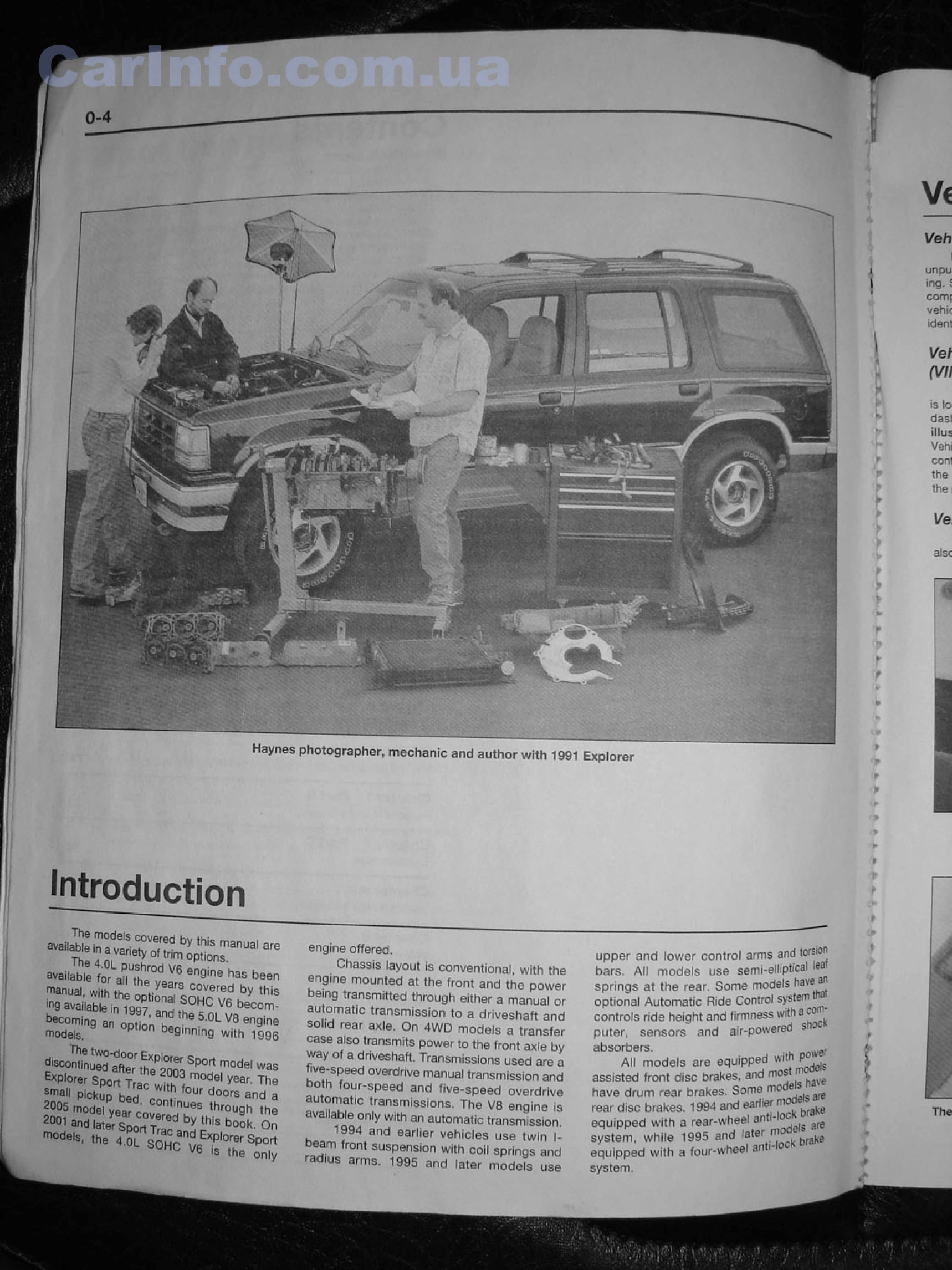
L- ■f к } ■- f f T* f t Haynes photographer, mechanic and author with 1991 Explorer t w Introduction 4 « C |# jfe V6 has been !* -* with the o p tlS ^ S O H C v l hby ,,lis ,rl9 available in 1 S 97 япн ,T v „ V6 becor>1' becoming an o p t i o r T ” * 5’° L V8 en9 'ne models, beginning with • ggp) S m a SpDrt mcdel was Explorer Sport Trac . 0Cfel * ear- The Small pickup bed eonlFr S and a — ‘ - « й г е г з д - engine offered. Chassis layout is conventional with the engine mounted at the front and the power being transmitted through either a manual or automatic transmission to a drives,haft and solid rear axle. On 4WD models a transfer case also transmits power to the front axle by way of a driveshaft. Transmissions used are a ^ve-speed overdrive manual transmission and both four-speed and five-speed overdrive automatic transmissions. The V8 engine is available only with an automatic transmission. 1 994 and earlier vehicles use twin J- ,m suspension with coil springs and arms 1095 and later models use upper and lower controf arms and torsion bars. Afl models use semi-alljptical :ea1 springs at the rear; Some modeis hav£ optional Automatic Ride Control system t-a controls ride height and firmness with a с puter, sensors and air-powered s .0 absorbers. . ^ AN models are equipped W l1 \ ,JiC ✓ли m uucis circr " irtHfilS assisted front disc brakes, and mo$* have drum rear brakes. Some mo * 0 rear disc brakes. 1994 and earlier rtf _ -wheel anti-loc equipped with a re a r-w ^ ara system, while 1995 and later m ■ ^ equipped with a ft>ur-whe 6 l яп * t > t t ; system. t
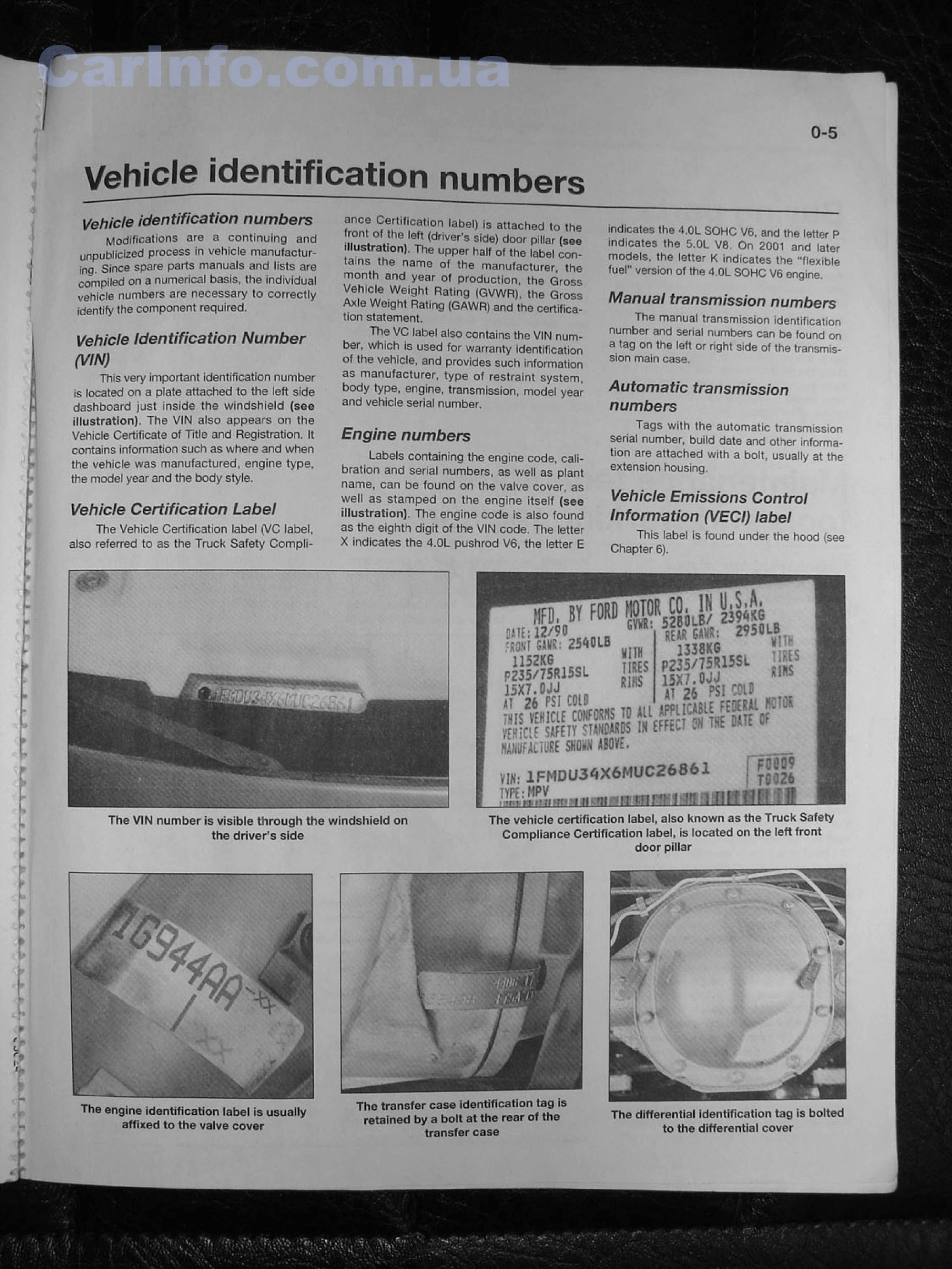
0’5 Vehicle identification numbers Vehicle identification numbers Modifications are a continuing and uftpublicized process in vehicle manufactur ing. Since spare parts manuals and lists are compiled on a numerical basis, the individual vehicle numbers are necessary to correctly identify the component required. Vehicle Identification Number (VIN) Thfs very important identification number is located on a plate attached to the left side dashboard just inside the windshield {see ^lustration). The VIN also appears on the Vehicle Certificate of Title and Registration. It contains information such as where and when the vehicle was manufactured, engine type, the model year and the body style. Vehicle Certification Label The Vehicle Certification label (VC label, also referred to as the Truck Safety Compli- ance Certification label) is attached lo the front of the left (driver's side) door pillar (see Illustration). The upper half of (he label con tains the name of the manufacturer, the month and year of production, the Gross Vehicle Weight Rating (GVWFt), the Gross We'9h1 Rating (GAWR) and the certifies- tion statement, 1 he VC label also contains the VIN num ber, which is used for warranly identification of the vehicle, and provides such information as manufacturer, type of restraint system, body type, engine, transmission, model year and vehicle serial number. Engine numbers Labels containing the engine code, cali bration and serial numbers, as well as plant name, can be found on the valve cover, as well as stamped on the engine itself (see illustration). The engine code is also found as the eighth digit of the VIN code. The letter X indicates the 4,QL pushrod V 6, the letter E indicates the -VOL SOHC VS. and the letter P indicates the 5,0L VS. On 2001 and later models, the letter К indicates the "Flexible fuel" version of (he 4,QL SOHC V 6 engine. Manual transmission numbers The manual transmission identification number and serial numbers can be found on a tag on Ihe left or right side of the transmis sion main case. Automatic transmission numbers Tags with the automatic transmission serial number, build date and other informa tion are attached with a bolt, usually at the extension housing. Vehicle Emissions Control Information (VECI) label This label is found under the hood [see Chapter 6 ). PJ33/75l№ '■№> 15X/.DJJ я. 81 дт ?6 PS1 $15 FPL [WilE FEDEW1 _ _ шял TiiF- ft 1 T_ П* JJifS: гЗйШ-В Ш 2К6 "i, PZ35/75R15SL ] «5 M «, I щ даШ Е SHOWM № F^rik УШ' 1 F M D L J3 $ X 6 M U C Z 6 8 6 1 ПК-. MPV . ............ .. TYPE: WPV ■''-''ИI'll( I РШ9 I ТШ 6 .. . 1L _1 The VIN number is visible through the windshield on The vehicle certification label, also known as the Truck Safety the driver's side Compliance Certification label, is located on the left front door pi liar The engine identification labet is usually affixed to the valve cover The transfer case identification tag is retained by a bolt at the rear of the transfer case The differential identification tag is bolted to the differentia! cover
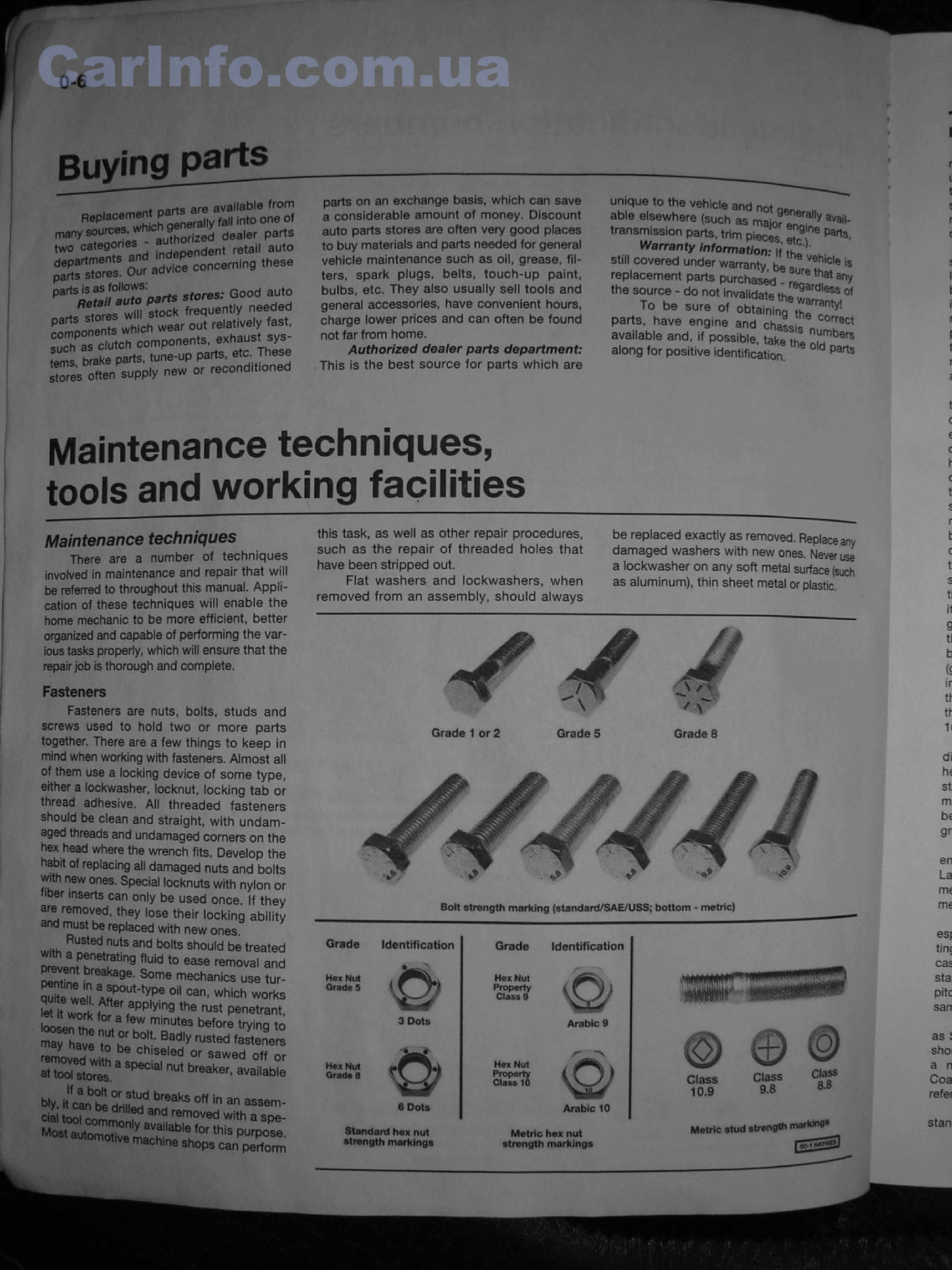
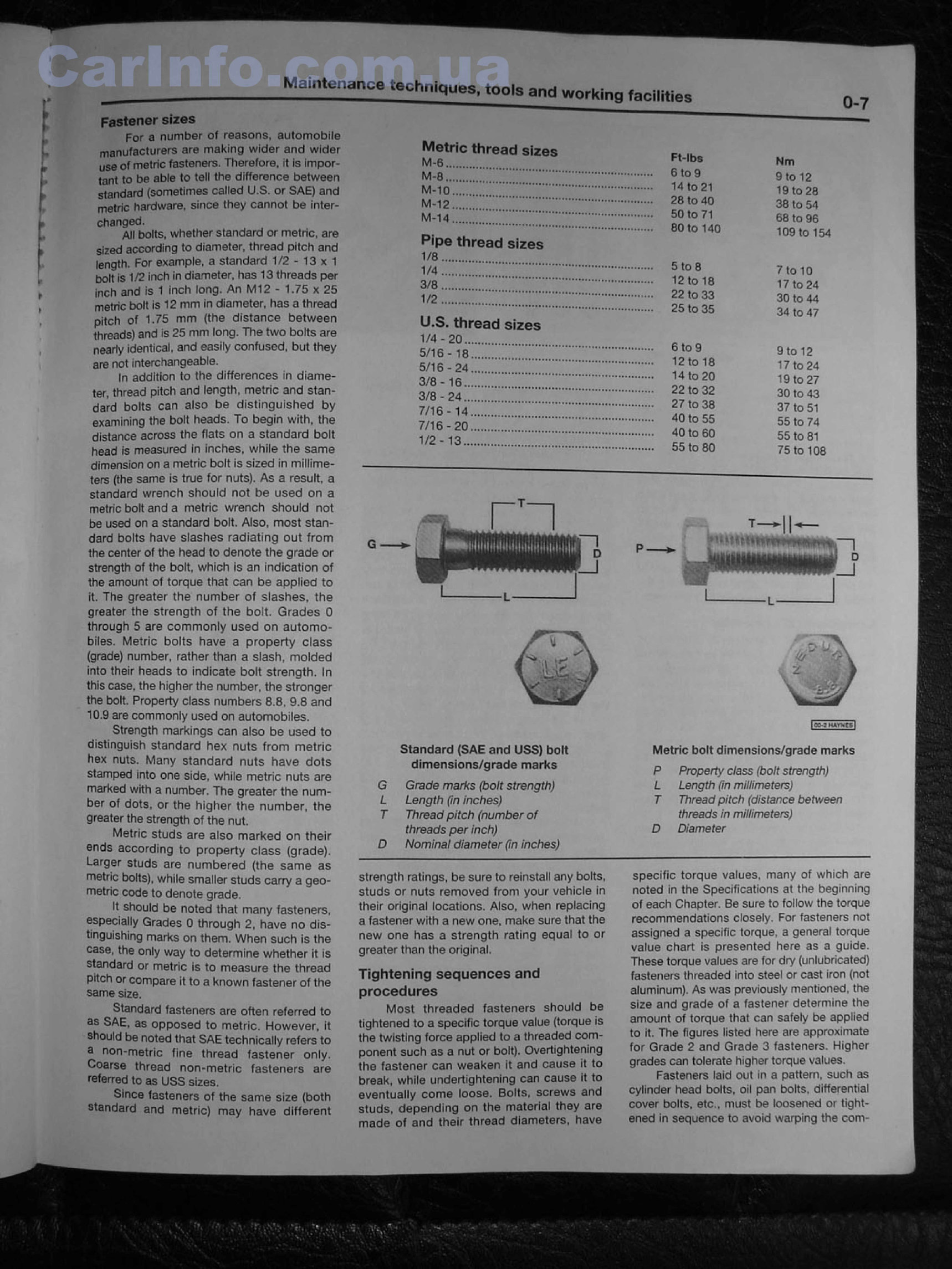
Metric thread sizes м-e ........... I . .................. . M-8 .......... ......... ........ M"10- - 1 ............ ................ M -12 .... ■ '*|1ЧЗ|||||кф4^||||||| M-14 ............... ............... Pipe thread sizes I/O ............ 1/4 .... . 3/Э ...... 1/2 ...... ...... ■ ■ “t + n ■ л я g в ■ ■ i ii , , U.S. thread sizes 1/4 - 20 ..................... 5/16-16............ 5/1S - 24 ...... 3/e -16 ........ 3/8-24 ........ 7/16 - 1 4 ...... 7/16 - 2 0 ...... 1/2 - 13 ........ * ....... .................. . . . ................ . ++ it таалш j J i i m p i m , вш j.j Ft-lbs 6 lo 9 14 (0 21 28 to 40 50 lo 71 SO to 140 5 to e 1 2 to 10 22 to 33 25 to 35 6 to 9 12 toia 14 to 20 22 to 32 27 to 38 40 to 55 40 to 60 55 to 80 Mm 9 lo 12 t9to28 38 to 54 6B to 96 109 to 154 7 to IQ 17 to 24 30 to 44 34 to 47 9 to 12 17 to 24 19 60 27 30 to 43 37 to 51 55 to 74 55 to 31 75 to 108 Fastener sizes For a number of reasons, automobile manufacturers are making wider and wider use of metric fasteners. Therefore, it is impor tant to be able to tall the difference between standard {sometimes called U,S. or SAE) and melric hardware, since they cannot be inter changed. All bolts, whether standard or metric, are sized according to diameter, thread pitch and length, For example, a standard 1 / 2 - 1 3 x 1 boft is 1/2 inch in diameter, has 13 threads per inch and is 1 fnch long. An M l2 - 1.75 x 25 metric bolt is 12 mm in diameter, has a thread pitch of 1,75 mm (the distance between threads) and is 25 mm fang. The two bolts are nearly identical, and easily confused, but they are not interchangeable. In addition to the differences in diame ter, thread pitch and length, me trie and stan dard bolts can also be distinguished by examining the bolt heads. To begin with, the distance across the flats on a standard bolt head is measured in fnches, while the same dimension on a metric boit rs sized in millime ters [the same is true for nuts). As a result, a standard wrench should not be used on a metric bolt and a metric wrench should not be used on a standard bolt Afso, most stan dard bolts have slashes radiating out from the center of the head to denote the grade or strength of the bolt, which fs an indication of the amount of torque that can be applied to ft. The greater the number of slashes, the greater the strength of the bolt. Grades 0 through 5 are commonly used on automo biles. Metric bolts have a property class [grade) number, rather than a slash, molded into their heads to indicate bolt strength. In this case, the higher the number, the stronger the bolt, Property class numbers 8 , 8 . 9.8 and 10,9 are commonly used on automobiles. Strength markings can also be used to distinguish standard hex nuts from metric he* nuts. Many standard nuts have dots stamped into one side, while metric nuts are marked with з number. The greater the num ber of dots, or the higher the number, the greater the strength of the nut. Metric studs are also marked on their ends according to property class (grade). Larger studs are numbered {the same as metric bolts), while smaller studs carry a geo metric code to denote grade. It should be noted that many fasteners, especially Grades 0 through 2 , have no dis tinguishing marks on them, When such is the case, the only way to determine whether it is standard or metric is to measure the thread pitch or compare it to a known fastener of the same size. Standard fasteners are often referred to as SAE, as opposed to metric. However, it should be noted that SAE technically refers to a non-metric fine thread fastener only. Coarse thread non-metric fasteners are referred to as USS sizes. Since fasteners of the same size [both standard and metric) may have different Standard (SAE and USS) bolt dimensions/grade marks G Grade marks (bolt strength) L Length (in inches) T Thread pitch (number of threads per inch) D Nominal diameter (in inches) studs or nuts removed from your vehicle in their original locations. Also, when replacing a fastener with a new one, make sure that the new one has a strength rating equal to or greater than the original. Tightening sequences and procedures Most threaded fasteners should be tightened to a specific torque value {torque is the twisting force applied to a threaded com ponent such as a nut or boll}. Overtightening the fastener can weaken it and cause it to break, while undertightening can cause it to eventually come loose. Bolts, screws and studs, depending on the material they are made of and their thread diameters, have fcc-зmvxcsl Metric bolt dimensions/grade marks P Property class (boft strength) L Length (in millimeters) T Thread pitch (distance between threads in millimeters) D Diameter noted in the Specifications at the beginning of each Chapter. Be sure to follow the torque recommendations closely. For fasteners not assigned a specific torque, a general torque value chart is presented here as a guide. These torque values are for dry (unlubricated) fasteners threaded into steel or cast iron (not aluminum). As was previously mentioned, the size and grade of a fastener determine the amount of torque that can sateiy be applied to it. The figures listed here are approximate for Grade 2 and Grade 3 fasteners, Higher grades can tolerate higher torque values. Fasteners laid out in a pattern, such as cylinder head bolts, oil pan bolts, differential cover bolts, etc,, must be loosened or tight ened in sequence to avoid warping the com- strength ratings, be sure to reinstall any bol'tsf specific torque values, many of which are
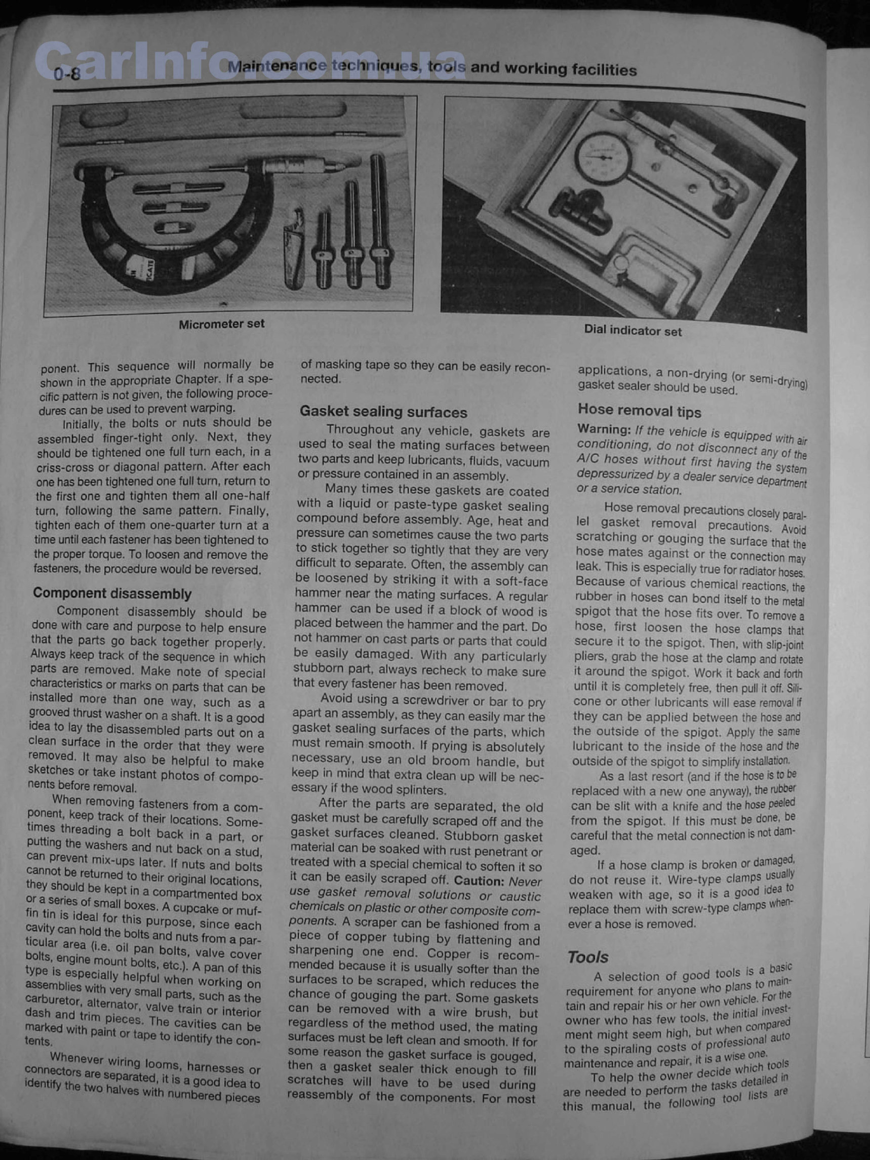
~ г г ^ГгГ' J''TBt i Jr Г'" Maintenance techniques, tools and working facilities Dial indicator set Micrometer set ponent This sequence will normaliy be shown in the appropriate Chapter. If a spe cific pattern is not given, the following proce dures can be used to prevent warping. Initially, the bolts or nuts should be assembled finger-tight only. Next, they should be tightened one full turn each, in a criss-cross or diagonal pattern. After each one has been tightened one full turn, return to the first one and tighten them all one-half turn, following the same pattern. Finally, tighten each of them one-quarter turn at a tfme until each fastener has been tightened to the proper torque. To foosen and remove the fasteners, the procedure would be reversed. Component disassembly Component disassembly should be done with care and purpose to help ensure that the parts go back together properly, Always keep track of the sequence in which parts are removed. Make note of special characteristics or marks on parts that can be installed more than one way, such as a grooved thrust washer on a shaft, it is a good idea to lay the disassembled parts out on a clean surface in the order that they were removed. It may also be helpful to make ske ches or take instant photos of compo nents before removat. When removing fasteners from a com- th trach of meir Nations. Some- Г : eading a bo,t back in a part or саГогеГДГ ' 116' 6 and back a siud, cannot he r * " UpS later- " nuts and bolts S nS S dtTV ? ,heir ori9ina! iocato"s. or a serie dof L Гк'П * COmpartmem^ box fin tin is ideal Г ЬГ 5- cupcake or ™ *- tt-«ttKS!bSr.r dash and trim pieces T ^ c a v 'H ° Г 'П‘е" ° Г marked with oaint ™ 7 ' °aV,tl0S can be tents. pe to ideritify №e con- connectors*^sepa?ated°vS' harnesses 0f identify the two h ii 1 ls a 900d idea *0 e two halv6s « *» numbered pieces of masking tape so they can be easily recon nected. Gasket sealing surfaces Throughout any vehicle, gaskets are used to seaF the mating surfaces between two parts and keep lubricants, fluids, vacuum or pressure contained in an assembly. Many times these gaskets are coated with a liquid oa paste-type gasket sealing compound before assembly. Age, heat and pressure can sometimes cause the two parts to stick together so tightly that they are very difficult to separate. Often, the assembly can be loosened by striking it with a soft-face hammer rear the mating surfaces. A regular hammer can be used if a block of wood is placed between the hammer and the part. Do not hammer on cast parts or parts that could be easily damaged. With any particularly stubborn part, always recheck to make sure that every fastener has been removed. Avoid using a screwdriver or bar to pry apart an assembly, as they can easily mar the gasket sealing surfaces of the parts, which must remain smooth. If prying is absolutely necessary, use an ofd broom handle, but keep in mind that extra clean up wifi be nec essary if the wood splinters. After the parts are separated, the old gasket must be carefully scraped off and the gasket surfaces cleaned. Stubborn gasket material can be soaked with rust penetrant or treated with a special chemicaf to soften it so it can be easily scraped off. Caution: Never use gasket removal solutions or caustic chemicals on plastic or other composite com ponents. A scraper can be fashioned from a piece of copper tubing by flattening and sharpening one end. Copper is recom mended because it is usually softer than the surfaces to be scraped, which reduces the chance of gouging the part. Some gaskets can be removed with a wire brush, but regardless of the method used, the mating surfaces must be left clean and smooth. If for some reason the gasket surface is gouged, then a gasket seafer thick enough to fill scratches will have to be used during reassembly of the components. For most applications, a non-drying {or semi * gasket sealer should be usee!, Hose removal tips Warning: If the vehicle fs equipped wfc, conditbning, do not disconnect aoy S Z A/С hoses without first having the depressurrzed by a dealer service d e /J iJ Z ora service station. Hose removal precautions closely parai lei gasket removal precautions. Avoid scratching or gouging the surface that th- hose mates against or the connection may leak. This is especially true for radiator hoses. Because of various chemical reactions, the rubber in hoses can bond itself to the metal spigot that the hose fits over. To rsmovs a hose, first ioosen the hose clamps that secure it to the spigot. Then, with slip-joint pfiers, grab the hose at the clamp and rotate it around the spigot. Worfc it back and forth until it is completely free, then pull it off, Sifi- cone or other lubricants will ease removal if they can be applied between the hose ала the outside of the sprgoL Apply the same lubricant to the inside of the hose and the outside of the spigot to simplify installation. As a last resort {and if the hose is to be replaced with a new one anyway), the rubber can be slit with a knife and the hose peeied from the spigot. If this must be done, be carefuf that the metal connection is not dam aged. If a hose clamp is broken or damaged- do not reuse it. Wire-type clamps usua ^ weaken with age, so it is a good ideai replace them with screw-type clamps № ■ ever a hose is removed. Tools A selection of good tools is * requirement for anyone who plans ^ tain and repair his or her own venic ■ . owner who has few fools, the mi ia_ Vj ment might seem high, but wheri ^ to the spiraling costs °/,p ад|ЭТ1в. maintenance and repair, it aist «■ ^ To help the o w n e r decide^ are needed to perform the • ( ire this manual, the following mol I»
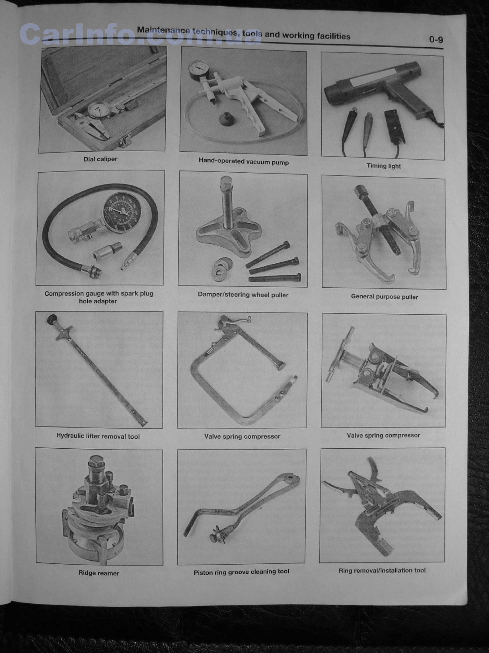
Hydraulic lifter removal tool Valve spring compressor Valve sprfng compressor M aintenance tech nigues.tools and working facilities Dial caliper Hand-operated vacuum pump Timing light Damper/steering wheel puller Compression gauge with spark plug hole adapter General purpose puller Piston ring groove cleaning tool Ring remove I/installation Lool Ridge reamer
Discover the 2002 Ford Explorer Sport Trac Service & Repair Manual, a comprehensive guide crafted to aid in the efficient maintenance and repair of your vehicle.
This manual offers step-by-step instructions, diagrams, and illustrations to assist in addressing various issues and conducting routine maintenance tasks on your 2002 Ford Explorer Sport Trac. It encompasses a wide array of topics, including:
Engine
Transmission
Electrical System
Brakes
Suspension
Exhaust System
Heating and Cooling
Body and Interior
By utilizing this dependable manual, you can effectively save time and money by resolving issues independently. Whether you are a DIY enthusiast or a professional mechanic, this manual will equip you with the essential resources to proficiently service and repair your 2002 Ford Explorer Sport Trac.
Acquire the 2002 Ford Explorer Sport Trac Service & Repair Manual today and gain the knowledge and confidence to maintain your vehicle in optimal condition.
Recently Viewed
5,521,897Happy Clients
2,594,462eManuals
1,120,453Trusted Sellers
15Years in Business
Price:
Actual Price:
2002 Ford Explorer Sport Trac Service & Repair Manual Software