2001 Ford Explorer Sport/Explorer Sport Trac Service & Repair Manual
What's Included?
Lifetime Access
Fast Download Speeds
Online & Offline Access
Access PDF Contents & Bookmarks
Full Search Facility
Print one or all pages of your manual
2001 ACCESSORIES & EQUIPMENT Passive Anti-Theft Systems - Explorer Sport & Explorer Sport Trac DESCRIPTION Passive Anti-Theft System (PATS) is designed to prevent driveaway thefts. System is passive in that it does not require any activity from user. System uses radio frequency identification technology to verify if proper key is being used to attempt to start vehicle. During each starting sequence, an encoded ignition key is interrogated by vehicle anti-theft electronics. If key's identification code is programmed into Powertrain Control Module (PCM), vehicle is capable of starting. If key's identification code is incorrect or missing, vehicle is prevented from starting. Early production models use a PATS transceiver module, and a PATS transceiver. PATS transceiver communicates with PATS transceiver module. PATS transceiver module determines if engine will be enabled to start. Late production models use a PATS transceiver and Powertrain Control Module (PCM). PATS transceiver communicates with PCM. PCM then determines if engine will be enabled to start. If PCM prevents vehicle from starting because of PATS, PCM will store a Diagnostic Trouble Code (DTC) in memory. PATS vehicle protection system consists of these components: anti-theft indicator (THEFT) light, PATS transceiver, encoded ignition key, module communications network and Data Link Connector (DLC). PATS have an unlimited key mode, that is intended for those customers who need more than 8 keys programmed. OPERATION ANTI-THEFT INDICATOR (THEFT) LIGHT THEFT indicator light located on right side of instrument cluster is used to prove out system operation status. Under normal operation THEFT indicator light will illuminate for 3 seconds when ignition switch is in RUN or START position, and then turn off. If a problem exists in PATS, THEFT indicator light will flash rapidly or illuminate constantly with ignition switch in RUN or START position. ENCODED IGNITION KEY When ignition switch is in RUN or START position, PATS initiates encoded ignition key interrogation process. PCM supplies both power and carrier signal to transceiver to momentarily energize ignition key. After energize NOTE: This article applies only to Explorer Sport and Explorer Sport Trac models. For 4-door Explorer testing procedures, see PASSIVE ANTI-THEFT SYSTEMS - EXPLORER & MOUNTAINEER article. NOTE: Explorer Sport and Explorer Sport Trac has 2 production levels: early production vehicles are built prior to July 24, 2000, and late production vehicles are built after July 24, 2000.
period has expired, key transmits its identification code to transceiver module. This encoded ignition key is much larger in size to accommodate the electronics located inside plastic cover. PASSIVE ANTI-THEFT SYSTEM TRANSCEIVER MODULE Transceiver receives ignition key identification code and sends signal to PATS transceiver module, on early production models. PASSIVE ANTI-THEFT SYSTEM TRANSCEIVER PATS contains circuitry to interface with vehicle electrical system, PATS transceiver, Module Communications Network (MCN) and THEFT indicator light. PCM stores ignition key codes in memory. PATS can be diagnosed through Data Link Connector (DLC). POWERTRAIN CONTROL MODULE On late production models, Passive anti-theft system uses PCM to enable or disable vehicle's engine. Within one second after engine starts, PCM must receive an enable signal or engine will not start. COMPONENT LOCATIONS COMPONENT LOCATIONS PROGRAMMING KEY PROGRAMMING - SECURITY ACCESS PROCEDURE Component Location Battery Junction Box Left Side Of Engine Compartment Passive Anti-Theft System Transceiver Module (Early Production) Behind Right Side Of Instrument Panel Passive Anti-Theft System Transceiver (Late Production) Bottom Right Side Of Steering Column Powertrain Control Module Rear Center Of Engine Compartment Starter Relay In Battery Junction Box THEFT Indicator Light Right Side Of Instrument Cluster NOTE: Security access must be granted to erase ignition keys, enable/disable spare key programming switch, or perform parameter reset for PATS transceiver. This procedure has a 10 minute time delay prior to granting security access during which the New Generation Star (NGS) tester must remain connected to vehicle. After security access has been granted, security access command menu is displayed which offers various command options. Only select command
Turn ignition switch to RUN position. Using NGS tester and Ford Service Function (FSF) card, select SECURITY ACCESS PROCEDURE. This procedure will take 10 minutes to perform. After security access procedure has been completed, a new menu will be displayed with command options. Select as many functions as required before exiting this menu. Once this menu is exited, security access procedure must be performed again to perform additional commands. KEY PROGRAMMING - WITH PROGRAMMED KEYS 1. Insert first programmed ignition key into ignition lock cylinder. Turn ignition switch from LOCK to RUN positions (ignition must stay in RUN position for 3 seconds). Turn ignition switch to LOCK position and remove ignition key from ignition lock cylinder. 2. Within 5 seconds of turning ignition switch to LOCK position, insert second programmed ignition key into ignition lock cylinder. Turn ignition switch from LOCK to RUN positions (ignition must stay in RUN position for 3 seconds). Turn ignition switch to LOCK position and remove second ignition key from ignition lock cylinder. 3. Within 20 seconds of turning ignition switch to LOCK position, insert a NEW unprogrammed ignition key into ignition lock cylinder. Turn ignition switch from LOCK to RUN positions (ignition must stay in RUN position for 3 seconds). Turn ignition switch to LOCK position and remove ignition key from ignition lock cylinder. NEW ignition key should now be programmed. To program additional key(s), repeat key programming procedure from step 1) . KEY PROGRAMMING - WITHOUT PROGRAMMED KEYS required by appropriate system test. NOTE: This procedure will only work if 2 or more programmed ignition keys are available and there is a need to program additional keys. If 2 keys are not available, perform KEY PROGRAMMING - WITHOUT PROGRAMMED KEYS . PID SPARE_KY must be enabled for this procedure to operate. To enable this PID, perform KEY PROGRAMMING - SECURITY ACCESS PROCEDURE and enable spare key programming switch. If programming procedure is successful, new key(s) will start vehicle and THEFT indicator light will illuminate for 3 seconds. If programming procedure is not successful, new key(s) will not start vehicle and THEFT indicator light will flash for one minute (after flashing for one minute, THEFT indicator light will flash fault code). If necessary, repeat programming procedure. If programming of key(s) is still unsuccessful, check for Diagnostic Trouble Codes (DTCs) and repair as necessary. See SELF - DIAGNOSTIC SYSTEM . If procedure is not performed as outlined, programming procedure will end. Ignition keys must have correct mechanical key cut for vehicle and must be an encoded key. NOTE: This procedure is used when a customer needs keys programmed into system and does not have 2 programmed ignition keys available, or when programmed ignition keys have been lost and/or ignition switch assembly has been replaced. This procedure will erase all programmed ignition keys from memory and
1. Turn ignition switch from LOCK to RUN positions. Using New Generation Star (NGS) tester, enter function test menu. Select SECURITY ACCESS PROCEDURE. This procedure will take 10 minutes to perform. After security access procedure has been completed, a new menu will be displayed with command options. Select IGNITION KEY CODE ERASE. 2. Turn ignition switch to LOCK position and disconnect NGS tester. Insert first encoded ignition key into ignition lock cylinder. Turn ignition switch to RUN position for 3 seconds. Turn ignition switch to LOCK position and remove first encoded key. 3. Insert second encoded ignition key into ignition lock cylinder. Turn ignition switch to RUN position for 3 seconds. Turn ignition switch to LOCK position and remove second encoded key. Both encoded ignition keys should now start vehicle. KEY PROGRAMMING - SPARE KEY PROGRAMMING SWITCH Insert a programmed ignition key into ignition lock cylinder. Turn ignition switch from LOCK to RUN. Using NGS tester and Ford Service Function (FSF) card, select SECURITY ACCESS PROCEDURE. This procedure will take 10 minutes to perform. After security access procedure has been completed, a new menu will be displayed with command options. Default setting on all new vehicles is ENABLE. Select SPARE KEY PROGRAMMING SWITCH. Set SPARE KEY PROGRAMMING SWITCH to ENABLE or DISABLE. TROUBLE SHOOTING Verify customers complaint. Ensure electronically coded ignition key is being used. Check for damaged ignition lock cylinder switch, damaged encoded ignition key or open fuses. Check for loose or corroded connectors, damaged wiring harness, damaged ignition switch or damaged PATS transceiver. If fault is found, repair as necessary. If no fault is found, perform self-diagnostics. See SELF - DIAGNOSTIC SYSTEM . SELF-DIAGNOSTIC SYSTEM Connect New Generation Star (NGS) tester to Data Link Connector (DLC), located beneath instrument panel. prevent vehicle from starting until 2 keys have been programmed. Ignition keys must have correct mechanical key cut for vehicle and must be an encoded key. If additional key(s) are to be programmed, perform KEY PROGRAMMING - WITH PROGRAMMED KEYS . If remaining keys are with customer and not with vehicle, instruct customer to see owner's manual to program spare key(s). NOTE: Spare key programming switch is a programmable switch which provides capability to enable/disable normal customer spare key programming procedure detailed in owner's manual. This programmable switch is provided as a convenience for rental company fleets or other fleet purchasers who may not want spare key programming procedure available to vehicle driver. Spare key programming switch state can be viewed using PID SPARE_KY PID. NOTE: Diagnostic procedures for early production models using PATS transceiver module and PATS transceiver are not available from manufacturer.
Using NGS tester, preform data link diagnostic test. See DATA LINK DIAGNOSTIC TEST under SELF- DIAGNOSTIC SYSTEM in MODULE COMMUNICATIONS NETWORK - EXPLORER SPORT & EXPLORER SPORT TRAC article. If NGS tester displays with CKT914, CKT915 or CKT70=ALL ECUS NO RESP/NOT EQUIP, repair module communications concern. See MODULE COMMUNICATIONS NETWORK - EXPLORER SPORT & EXPLORER SPORT TRAC article. If NGS tester displays NO RESP/NOT EQUIP for Powertrain Control Module (PCM), perform appropriate test in MODULE COMMUNICATIONS NETWORK - EXPLORER SPORT & EXPLORER SPORT TRAC article. If NGS tester displays with SYSTEM PASSED, retrieve and record continuous DTCs. Erase continuous DTCs. Using NGS tester, perform PATS module self-test. If any DTCs are retrieved, perform appropriate test. See POWERTRAIN CONTROL MODULE DIAGNOSTIC TROUBLE CODE INDEX table. Codes listed in this table are only for testing covered in this article. For complete DTC listing, see MODULE COMMUNICATIONS NETWORK - EXPLORER SPORT & EXPLORER SPORT TRAC article. If no DTCs are present, repair by symptom. See SYMPTOM INDEX table under SYSTEM TESTS. POWERTRAIN CONTROL MODULE DIAGNOSTIC TROUBLE CODE INDEX SYSTEM TESTS SYMPTOM INDEX DTC (1) Description Perform Test B1213 Number Of Programmed Ignition Keys Below Minimum F B1342 ECU Defective (2) B1600 Passive Anti-Theft System Ignition Key Transponder Signal Not Received B B1601 Passive Anti-Theft System Received Incorrect Key Code From Ignition Key Transponder C B1602 Passive Anti-Theft System Received Invalid Key Code Format From Ignition Key Transponder D B1681 Passive Anti-Theft System Transceiver Signal Is Not Received E B2103 Antenna Not Connected A (1) Codes listed in this table are only for testing covered in this article. For complete DTC listing, see MODULE COMMUNICATIONS NETWORK - EXPLORER SPORT & EXPLORER SPORT TRAC article. (2) Using NGS tester, retrieve and document continuous DTCs. Clear all DTCs. Perform PCM self-test. If DTC B1342 is retrieved again, replace PCM. Symptom Perform Test No Communication With Powertrain Control Module (1) THEFT Indicator Never/Always Illuminates Or THEFT Indicator Does Not Prove Out G Vehicle Does Not Start H (1) See MODULE COMMUNICATIONS NETWORK - EXPLORER SPORT &
TEST A: ANTENNA NOT CONNECTED (DTC B2103) 1. Turn ignition switch to LOCK position. Verify Passive Anti-Theft System (PATS) transceiver is installed properly. See PASSIVE ANTI - THEFT SYSTEM TRANSCEIVER under REMOVAL & INSTALLATION. If PATS transceiver is installed properly, go to next step. If PATS transceiver is not installed properly, repair as necessary. Clear DTCs and check system for normal operation. 2. Using New Generation Star (NGS) tester, retrieve and record continuous DTCs. Clear DTCs and perform Powertrain Control Module (PCM) self-test. If DTC B2103 is retrieved, replace PATS transceiver. Clear DTCs and repeat self-test. If DTC B2103 is not retrieved, system is operating properly at this time. TEST B: PASSIVE ANTI-THEFT SYSTEM IGNITION KEY TRANSPONDER SIGNAL NOT RECEIVED (DTC B1600) 1. Turn ignition switch to LOCK position. Using New Generation Star (NGS) tester, retrieve and record continuous DTCs. Clear DTCs and perform Powertrain Control Module (PCM) self-test. If DTC B1600 is retrieved, go to next step. If no DTCs are retrieved, system is operating properly at this time. 2. Obtain NEW encoded ignition key and insert into ignition lock cylinder. Turn ignition switch to RUN position. Program NEW encoded ignition key. See KEY PROGRAMMING - WITHOUT PROGRAMMED KEYS under PROGRAMMING. Using NGS tester, clear DTCs and repeat PCM self- test. If DTC B1600 is still retrieved, go to next step. If no DTCs are retrieved, system is operating properly at this time. 3. Turn ignition switch to LOCK position. Replace PATS transceiver. See PASSIVE ANTI - THEFT SYSTEM TRANSCEIVER under REMOVAL & INSTALLATION. Using customers original encoded ignition key, repeat PCM self-test. If DTC B1600 is retrieved, go to next step. If DTC B1600 is not retrieved, system is operating properly at this time. 4. Disconnect all PCM harness connectors, located behind center of instrument panel. Inspect for corroded or pushed out terminals. Connect all PCM harness connectors. Operate system and verify if concern is still exists. If concern still exists, replace PCM. If concern does not exist, system is operating correctly at this time. Concern may have been caused by a loose or corroded connector. TEST C: PASSIVE ANTI-THEFT SYSTEM RECEIVED INCORRECT KEY CODE FROM IGNITION KEY TRANSPONDER (DTC B1601) EXPLORER SPORT TRAC article. NOTE: Large metallic objects, a second PATS ignition key, or devices such as electronic credit cards on same key ring may cause vehicle starting problem and possibly set this code. Ensure customers encoded ignition key is an approved Ford encoded ignition key. Encoded keys from Rotunda is the only approved key. NOTE: Large metallic objects, a second PATS ignition key, or devices such as electronic credit cards on same key ring may cause vehicle starting problem and possibly set this code. Ensure customers encoded ignition key is an approved Ford encoded ignition key. Encoded keys from Rotunda is the only
1. Using New Generation Star (NGS) tester, retrieve and record continuous DTCs. Clear DTCs and repeat Powertrain Control Module (PCM) self-test. If DTC B1601 is retrieved, go to next step. If no DTCs are retrieved, system is operating properly at this time. Check all other customer encoded ignition keys to ensure they are programmed. 2. Using NGS tester, select PCM PID NUMKEYS. If NGS tester does not display 8, go to next step. If NGS tester displays 8, erase and reprogram key codes. See KEY PROGRAMMING - WITHOUT PROGRAMMED KEYS under PROGRAMMING. 3. Verify that at least 2 programmed encoded ignition keys are available with vehicle. If 2 programmed encoded ignition keys are available with vehicle, go to next step. If 2 programmed encoded ignition keys are not available with vehicle, obtain 2 NEW encoded ignition keys. Program NEW encoded ignition keys. See KEY PROGRAMMING - WITHOUT PROGRAMMED KEY under PROGRAMMING. After keys are programmed, go to step 5 . 4. Using NGS tester, select PID SPARE_KY. If PID SPARE_KY indicates YES, perform KEY PROGRAMMING - WITH PROGRAMMED KEY under PROGRAMMING. Retest system operation. If PID SPARE_KY does not indicate YES, perform KEY PROGRAMMING - SPARE KEY PROGRAMMING SWITCH under PROGRAMMING. 5. Turn ignition switch to LOCK position. Using first encoded ignition key, turn ignition switch to RUN position for 3 seconds. Turn ignition switch to LOCK position and remove first encoded ignition key. Using second ignition key, turn ignition switch to RUN position for 3 seconds. Attempt to start vehicle with second encoded ignition key. If vehicle does not start using second encoded ignition key, go to next step. If vehicle starts using second encoded ignition key, system is operating properly at this time. If additional spare encoded ignition keys need to be programmed, perform KEY PROGRAMMING - SPARE KEY PROGRAMMING SWITCH under PROGRAMMING. 6. Using NGS tester, retrieve and record continuous DTCs. Clear DTCs and repeat PCM self-test. If DTC B1601 is retrieved, go to next step. If no DTCs are retrieved, system is operating properly at this time. 7. Disconnect all PCM harness connectors, located behind center of instrument panel. Inspect for corroded or pushed out terminals. Connect all PCM harness connectors. Operate system and verify if concern is still exists. If concern still exists, replace PCM. If concern does not exist, system is operating correctly at this time. Concern may have been caused by a loose or corroded connector. TEST D: PASSIVE ANTI-THEFT SYSTEM RECEIVED INVALID KEY CODE FORMAT FROM IGNITION KEY TRANSPONDER (DTC B1602) approved key. NOTE: PCM disables engine for 20 seconds every time DTC B1601 is set. Ignition switch must remain in RUN position for at least 20 seconds before an attempt is made to start vehicle with any encoded ignition key. NOTE: Large metallic objects, a second PATS ignition key, or devices such as electronic credit cards on same key ring may cause vehicle starting problem and possibly set this code. Ensure customers encoded ignition key is an approved Ford encoded ignition key. Encoded keys from Rotunda is the only approved key.
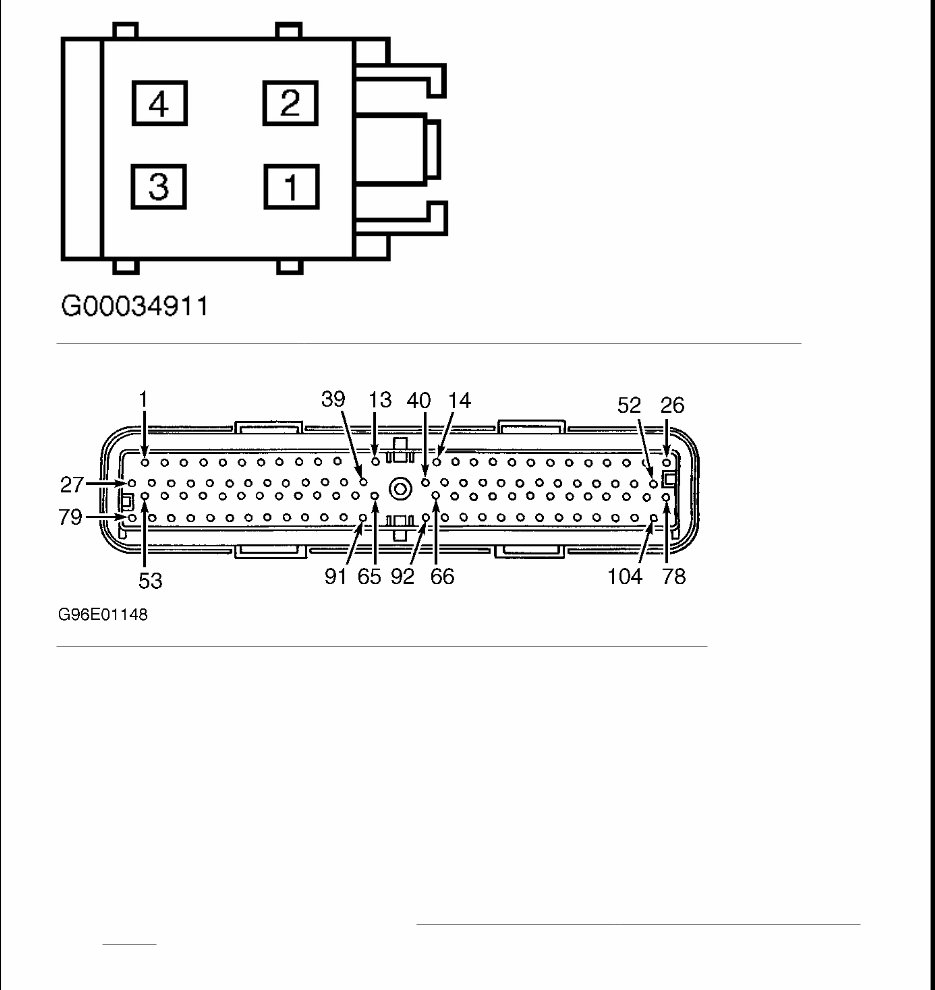
1. Using New Generation Star (NGS) tester, retrieve and record continuous DTCs. Clear DTCs and repeat Powertrain Control Module (PCM) self-test. If DTC B1602 is retrieved, go to next step. If DTC B1602 is not retrieved, system is operating properly at this time. 2. Obtain a NEW encoded ignition key. Program NEW key. See KEY PROGRAMMING - WITHOUT PROGRAMMED KEYS under PROGRAMMING. Retrieve DTCs. If DTC B1602 is retrieved, go to next step. If no DTCs are retrieved, system is operating properly at this time. If customer has any other encoded ignition keys at home, instruct customer to see owner's manual to program spare key(s). 3. Turn ignition switch to LOCK position. Replace PATS transceiver. See PASSIVE ANTI - THEFT SYSTEM TRANSCEIVER under REMOVAL & INSTALLATION. Turn ignition switch to RUN position. Using NGS tester, repeat PCM self-test. If DTC B1602 is retrieved, replace PCM. If DTC B1602 is not retrieved, system is operating properly at this time. TEST E: PASSIVE ANTI-THEFT SYSTEM TRANSCEIVER SIGNAL IS NOT RECEIVED (DTC B1681) 1. Using New Generation Star (NGS) tester, retrieve and record continuous DTCs. Clear DTCs, then repeat Powertrain Control Module (PCM) self-test. If DTC B1681 is retrieved, go to next step. If DTC B1681 is not retrieved, system is operating properly at this time. 2. Turn ignition switch to LOCK position. Disconnect Passive Anti-Theft System (PATS) transceiver 4-pin harness connector C2097, located at bottom right side of steering column. Turn ignition switch to RUN position. Measure voltage between ground and PATS transceiver harness connector C2097 terminal No. 2 (Dark Green/White wire). See Fig. 1 . If voltage is 10 volts or more, go to next step. If voltage is less than 10 volts, repair open in Dark Green/White wire between PATS transceiver and central junction box, located behind left side of instrument panel. Clear DTCs and retest system operation. 3. Turn ignition switch to LOCK position. Measure resistance between ground and PATS transceiver harness connector C2097 terminal No. 1 (Black/White wire). If resistance is less than 5 ohms, go to next step. If resistance is 5 ohms or more, repair Black/White wire between PATS transceiver and ground point. Ground point is located on center console below instrument panel. Clear DTCs and retest system operation. 4. Connect PATS transceiver harness connector. Turn ignition switch to RUN position. Measure voltage by backprobing between ground and PATS transceiver harness connector C2097 terminal No. 3 (Gray/Orange wire). See Fig. 1 . If voltage is less than 9 volts, go to next step. If voltage is 9 volts or more, go to step 6 . 5. Turn ignition switch to LOCK position. Disconnect PATS transceiver 4-pin harness connector C2097, located at bottom right side of steering column. Measure resistance between ground and PATS transceiver harness connector C2097 terminal No. 3 (Gray/Orange wire). If resistance is 10 k/ohms or more, go to next step. If resistance is less than 10 k/ohms or less, repair short to ground in Gray/Orange wire between PATS transceiver and PCM. Clear DTCs and retest system operation. 6. Turn ignition switch to LOCK position. Disconnect PATS transceiver 4-pin harness connector C2097, located at bottom right side of steering column. Disconnect PCM 104-pin harness connector, located rear center of engine compartment. Measure resistance of Gray/Orange wire between PATS transceiver harness connector C2097 terminal No. 3 and PCM harness connector C175 terminal No. 17. See Fig. 1 and Fig. 2 . If resistance is less than 5 ohms, go to next step. If resistance is 5 ohms or more, repair open Gray/Orange wire. Clear DTCs and retest system operation. 7. Turn ignition switch to LOCK position. Connect PATS transceiver harness connector C2097 and PCM
harness connector C175. Turn ignition switch to RUN position. Measure voltage by backprobing between ground and transceiver harness connector C2097 terminal No. 4 (White/Light Green wire). See Fig. 1 . If voltage is less than 9 volts, go to next step. If voltage is 9 volts or more, go to step 11 . 8. Turn ignition switch to LOCK position. Disconnect PCM 104-pin harness connector C175, located rear center of engine compartment. Measure resistance between ground and PCM harness connector C175 terminal No. 18 (White/Light Green wire). See Fig. 2 . If resistance is less than 10 k/ohms, go to next step. If resistance is 10 k/ohms or more, go to step 10 . 9. Disconnect PATS transceiver 4-pin harness connector C2097, located at bottom right side of steering column. Measure resistance between ground and PATS transceiver harness connector C2097 terminal No. 4 (White/Light Green wire). If resistance is 10 k/ohms or more, replace PATS transceiver. If resistance is less than 10 k/ohms, repair short to ground in White/Light Green wire between PATS transceiver and PCM. Clear DTCs and retest system operation. 10. Disconnect PATS transceiver 4-pin harness connector C2097, located at bottom right side of steering column. Measure resistance of White/Light Green wire between PCM harness connector C175 terminal No. 18 and PATS transceiver harness connector C2097 terminal No. 4. See Fig. 1 and Fig. 2 . If resistance is less than 5 ohms, go to step 13 . If resistance is 5 ohms, repair open in White/Light Green wire. 11. Ensure ignition switch is in RUN position. Using NGS tester, select PCM active command TRANSMIT SIGNAL COMMAND. Trigger TRANSMIT ON. Measure voltage by backprobing between ground and PATS transceiver harness connector C2097 terminal No. 4 (White/Light Green wire). See Fig. 1 . If voltage is 5 volts or more, go to next step. If voltage is less than 5 volts, replace PATS transceiver. 12. Turn ignition switch to LOCK position. Disconnect PCM 104-pin harness connector C175, located rear center of engine compartment. Disconnect PATS transceiver 4-pin harness connector C2097, located at bottom right side of steering column. Turn ignition switch to RUN position. Measure voltage between ground and PATS transceiver harness connector C2097 terminal No. 4 (White/Light Green wire). If voltage does not exist, go to next step. If voltage exists, repair short to voltage in White/Light Green wire between PATS transceiver and PCM. 13. Disconnect all PCM harness connectors, located behind center of instrument panel. Inspect for corroded or pushed out terminals. Connect all PCM harness connectors. Operate system and verify if concern is still exists. If concern still exists, replace PCM. If concern does not exist, system is operating correctly at this time. Concern may have been caused by a loose or corroded connector.
Fig. 1: Identifying Passive Anti - Theft System Transceiver Harness Connector C2097 Terminals Courtesy of FORD MOTOR CO. Fig. 2: Identifying Powertrain Control Module Harness Connector C175 Terminals Courtesy of FORD MOTOR CO. TEST F: NUMBER OF PROGRAMMED IGNITION KEYS BELOW MINIMUM (DTC B1213) 1. Using New Generation Star (NGS) tester, retrieve and record continuous DTCs. Clear DTCs and perform Powertrain Control Module (PCM) self-test. If DTC B1213 is retrieved, go to next step. If no DTCs are retrieved, system is operating properly at this time. Check system for normal operation. Repeat self-test. 2. Using NGS tester, monitor PCM PID NUMKEYS. If PCM PID NUMKEYS indicates less than 2 encoded ignition keys programmed, go to next step. If PCM PID NUMKEYS does not indicate less than 2 encoded ignition keys programmed, system is operating properly at this time. Clear DTCs and check system for normal operation. 3. Obtain NEW encoded ignition key and insert into ignition lock cylinder. Turn ignition switch to RUN position. Program NEW encoded key. See KEY PROGRAMMING - WITHOUT PROGRAMMED KEYS under PROGRAMMING. If THEFT indicator does not illuminate for 3 seconds and go out, go to next step. If THEFT indicator light illuminates for 3 seconds and goes out, system is operating properly. 4. Using NGS tester, monitor PCM PID SERV_MOD. If PCM PID SERV_MOD indicates YES, program
Introducing the 2001 Ford Explorer Sport/Explorer Sport Trac Service & Repair Manual!
Whether you're a professional mechanic or a DIY enthusiast, this service and repair manual is essential for anyone who owns a 2001 Ford Explorer Sport or Explorer Sport Trac. It is designed to offer comprehensive guidance for all repair and maintenance requirements, serving as the ultimate companion for your vehicle.
The manual features detailed step-by-step instructions, illustrations, diagrams, and specifications, ensuring that you have all the necessary information to confidently handle any service or repair task.
Key features include:
Complete coverage of all systems and components
Thorough troubleshooting guides for issue identification and resolution
Diagnostic charts for efficient problem-solving
Detailed maintenance schedules to keep your vehicle operating at its best
Comprehensive wiring diagrams for easy electrical repairs
Specifications and torque values for proper assembly and disassembly
This service and repair manual is suitable for the following models:
2001 Ford Explorer Sport Trac Base
2001 Ford Explorer Sport Trac XL
2001 Ford Explorer Sport Trac XLT
Invest in the 2001 Ford Explorer Sport/Explorer Sport Trac Service & Repair Manual today and empower yourself with the knowledge to keep your vehicle running smoothly.
Recently Viewed
5,521,897Happy Clients
2,594,462eManuals
1,120,453Trusted Sellers
15Years in Business
Price:
Actual Price:
2001 Ford Explorer Sport/Explorer Sport Trac Service & Repair Manual