2001 FORD EXPLORER OEM Workshop DIY Service Repair Manual
What's Included?
Lifetime Access
Fast Download Speeds
Offline Viewing
Access Contents & Bookmarks
Full Search Facility
Print one or all pages of your manual
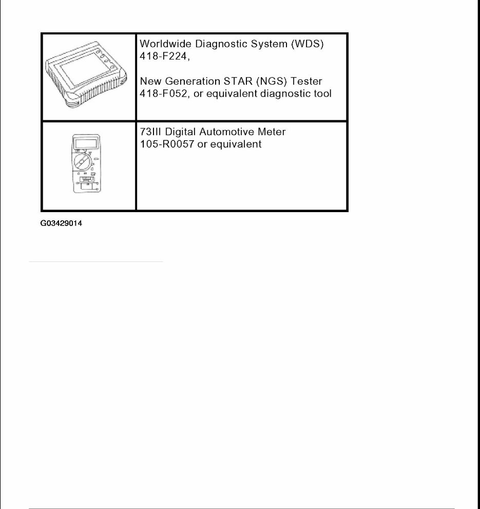
2002 BODY & ACCESSORIES Anti-Theft - PATS - Explorer & Mountaineer SPECIFICATIONS TORQUE SPECIFICATIONS TORQUE SPECIFICATIONS DESCRIPTION AND OPERATION ANTI-THEFT -PASSIVE The passive anti-theft system (PATS) contains the following components: z theft indicator z encoded ignition key z PATS transceiver module z powertrain control module (PCM) z standard corporate protocol (SCP) communication network DIAGNOSIS AND TESTING ANTI-THEFT -PASSIVE Refer to ANTI - THEFT (Explorer) or ANTI-THEFT (Mountaineer) for schematic and connector information. Special Tool(s) Description Nm lb-ft lb-in Anti -theft transceiver module screw 2 18 Lower instrument panel steering column cover screws 9 80 Steering column opening cover reinforcement bolts 15 11
Fig. 1: Identifying Special Tool(s) Courtesy of FORD MOTOR CO. Principles of Operation The PATS uses a specially encoded ignition key. Each encoded ignition key contains a permanently installed electronic device called a transponder. Each transponder contains a unique electronic identification code out of over 18 billion, billion combinations. The passive anti-theft system (PATS), also known as SecuriLock(R), uses radio frequency identification technology to deter a drive-away theft. This system is known as SecuriLock(R) in North America, Safeguard(R) in the U.K., and PATS in Continental Europe. Passive means that it does not require any activity from the user. The SecuriLockr System (PATS) is not compatible with aftermarket remote start systems, which allow the vehicle to be started from outside the vehicle. These systems may reduce the vehicle security level, and also may cause no-start issues. If equipped the remote start system must be removed before investigation of PATS- related, no-start issues. Each encoded ignition key must be programmed into the vehicle's powertrain control (PCM) before it can be used to start the engine. There are special diagnostic repair procedures described in this section that must be carried out if a new encoded ignition key is necessary. This system contains a new feature named Unlimited Key Mode. This feature allows a customer to program more than eight keys to the vehicle if they request it. Each vehicle in Unlimited Key Mode is set up with a
special Unlimited Transponder Security Key. This allows all the customer vehicles to share the same keys, but no other keys from outside can be used to operate the vehicles. For an individual customer, any randomly selected Security Key is acceptable. Refer to Unlimited Key Mode Programming in KEY PROGRAMMING SWITCH STATE CONTROL . The PATS transceiver module communicates with the encoded ignition key. The module is located behind the steering column shroud and contains an antenna connected to a small electronics module. During each vehicle start sequence, the transceiver module reads the encoded ignition key identification code and sends data to the PCM. The control functions are contained in the PCM. This module carries out all of the PATS functions, such as receiving the identification code from the encoded ignition key and controlling the engine enable. The PCM initiates the key interrogation sequence when the vehicle ignition switch is turned to RUN or START. All elements of the PATS must be functional before the engine is allowed to start. If any of the components are not working correctly, the vehicle will not start. The PATS uses a visual theft indicator. The indicator will prove out for three seconds when the ignition switch is turned to RUN or START under normal operation. If there is a PATS concern, this indicator will either flash rapidly or glow steadily when the ignition switch is turned to RUN or START. The PATS system also flashes the theft indicator every two seconds at ignition OFF to act as a visual deterrent. The PATS will be activated and will disable the vehicle from starting if there is a: z incorrectly encoded ignition key z damaged encoded ignition key z unprogrammed key z non-encoded key (key has no electronics) z damaged wiring z damaged transceiver z damaged PCM Inspection and Verification 1. Verify the customer concern by operating the system. 2. Visually inspect for obvious signs of mechanical and electrical damage. VISUAL INSPECTION CHART Mechanical Electrical z Large metallic objects, a second ignition key on the same key ring as the PATS ignition key or electronic devices on the key chain that can be use to purchase gasoline or similar items z Central junction box (CJB) fuse 14 (5A) z Ignition lock cylinder z PATS transceiver module
3. If an obvious cause for an observed or reported concern is found, correct the cause (if possible) before proceeding to the next step. 4. If the diagnostic tool does not power up, refer to the diagnostic tool manual. 5. Carry out the DATA LINK DIAGNOSTICS test. If the diagnostic tool responds with: z CKT914, CKT 693, CKT915 or CKT70 = ALL ECUS NO RESP/NOT EQUIP, refer to MODULE COMMUNICATIONS NETWORK . z NO RESP/NOT EQUIP for BSM, refer to MULTIFUNCTION ELECTRONIC MODULE . z SYSTEM PASSED, retrieve and record the continuous diagnostic trouble codes (DTCs), erase the continuous DTCs, and carry out the self-test diagnostics for the PCM. 6. If the DTCs retrieved are related to the concern, go to the POWERTRAIN ELECTRONIC CONTROL DIAGNOSTIC TROUBLE CODE (DTC) INDEX . 7. If no DTCs related to the concern are retrieved, proceed to the SYMPTOM CHART to continue diagnostics. Powertrain Electronic Control Diagnostic Trouble Code (DTC) Index POWERTRAIN ELECTRONIC CONTROL DIAGNOSTIC TROUBLE CODE INDEX Symptom Chart z PATS key z PCM z Use of a non-PATS key z Ignition switch z More than one PATS key on key chain z Loose or corroded connection(s) DTC Description Source Action B1213 Anti -Theft Number of Programmed Keys Is Below Minimum PCM GO to PINPOINT TEST F . B2431 Transponder Program Failure PCM Verify if using correct PATS key, if defective use new key B1342 ECU Defective (EEFROM in PCM not working) PCM Verify if using correct PATS key, if defective use new key B2103 Antenna Not Connected PCM GO to PINPOINT TEST A . B1600 PATS Ignition Key Transponder Signal Is Not Received PCM GO to PINPOINT TEST B . B1601 PATS Received Incorrect Key-Code From Ignition Key Transponder PCM GO to PINPOINT TEST C . B1602 PATS Received Invalid Format of Key-Code From Ignition Key Transponder PCM GO to PINPOINT TEST D . B1681 PATS Transceiver Module Signal Is Not Received PCM GO to PINPOINT TEST E . - All other DTCs PCM refer to MULTIFUNCTION ELECTRONIC MODULE .
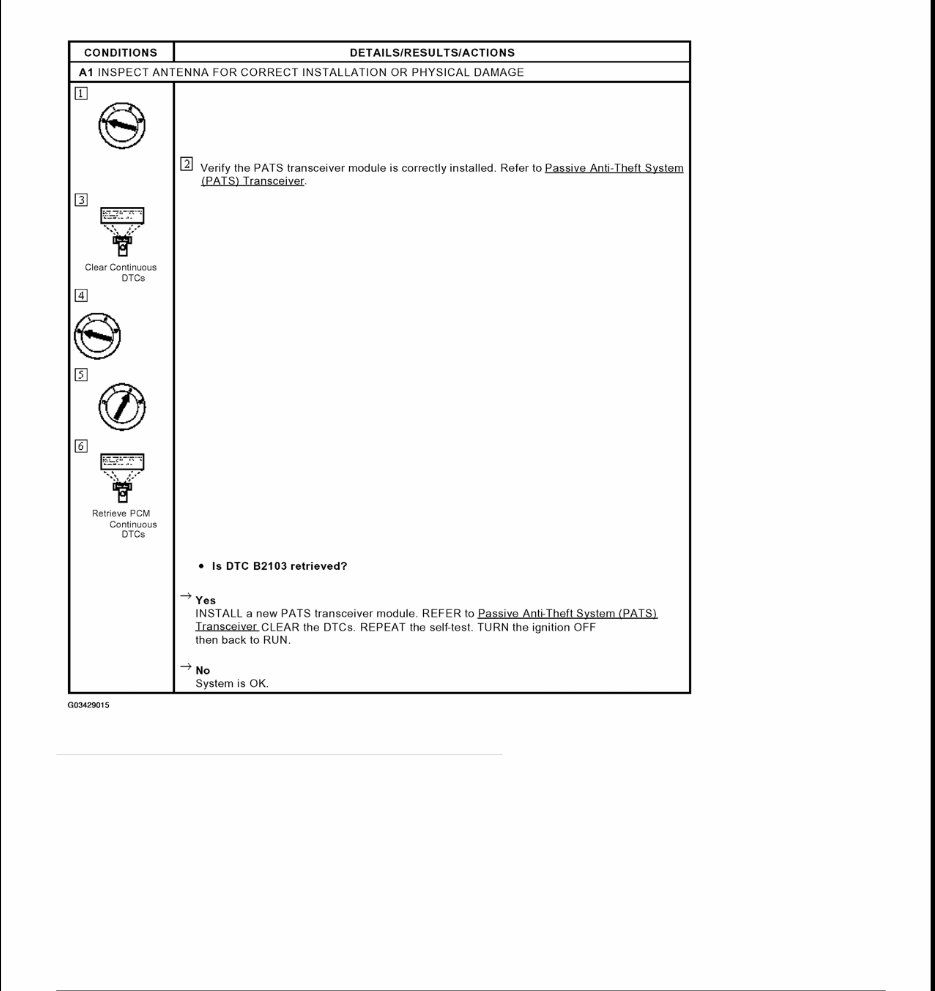
Symptom Chart SYMPTOM CHART Pinpoint Tests PINPOINT TEST A: NO ANTENNA DETECTED Condition Possible Sources Action z The anti-theft indicator is always/never on z Circuitry. z Theft LED. z Powertrain electronic control PCM). z GO to PINPOINT TEST G . z The vehicle does not start z Starter relay. z PCM. z Circuitry. z Encoded ignition key. z Ignition key code. z Ignition key transponder key code. z Ignition key transponder key code format. z GO to PINPOINT TEST H .
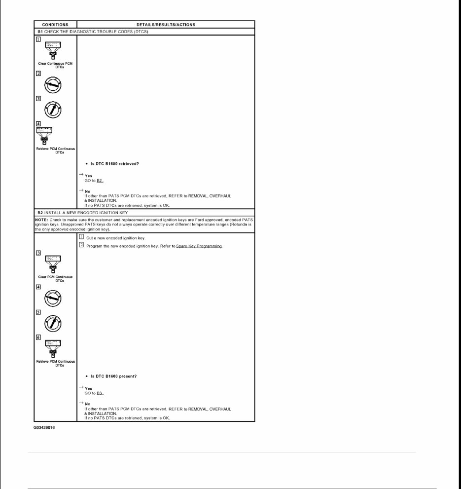
Fig. 2: Identifying Pinpoint Test A: No Antenna Detected Courtesy of FORD MOTOR CO. PINPOINT TEST B: PATS IGNITION KEY TRANSPONDER SIGNAL IS NOT RECEIVED NOTE: Large metallic objects, electronic devices on the key chain that can be used to purchase gasoline or similar items, or a second key on the same key ring as the PATS ignition key may cause vehicle starting problems and record DTCs under certain conditions. If a fault cannot be identified, examine the customer's key ring for such objects or devices. If present, inform the customer that they need to keep these objects from touching the PATS ignition key while starting the engine. These objects and devices cannot damage the PATS ignition key, but
can cause a momentary concern if they are too close to the key during engine start. If a concern occurs, turn ignition OFF and restart the engine with all other objects on the key ring held away from the ignition key. Check to make sure the encoded ignition key used by the customer is a Ford approved encoded ignition key (Rotunda is the only approved encoded ignition key).
Fig. 3: Identifying Pinpoint Test B: Pats Ignition Key Transponder Signal Is Not Received (B1 & B2) Courtesy of FORD MOTOR CO.
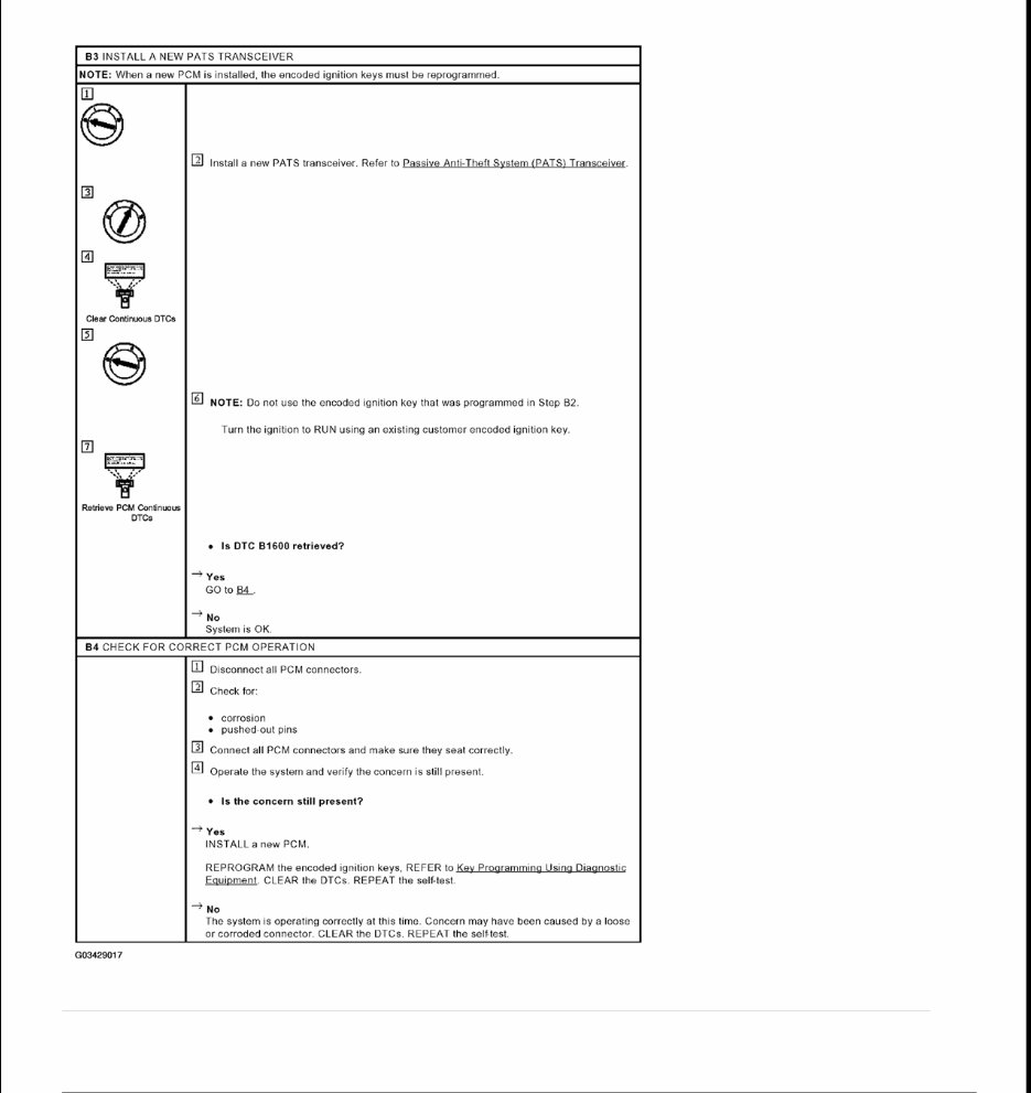
Fig. 4: Identifying Pinpoint Test B: Pats Ignition Key Transponder Signal Is Not Received (B3 & B4) Courtesy of FORD MOTOR CO. PINPOINT TEST C: PATS RECEIVED INCORRECT KEY-CODE FROM IGNITION KEY TRANSPONDER
NOTE: The PCM disables the engine for 20 seconds every time DTC B1601 is set. The ignition must remain in the run position for at least 20 seconds before an attempt is made to start the vehicle with any encoded ignition key. Check the PCM PID ANTISCAN for this unprogrammed key timeout status. NOTE: Large metallic objects, electronic devices on the key chain that can be used to purchase gasoline or similar items, or a second key on the same key ring as the PATS ignition key may cause vehicle starting problems and record DTCs under certain conditions. If a fault cannot be identified, examine the customer's key ring for such objects or devices. If present, inform the customer that they need to keep these objects from touching the PATS ignition key while starting the engine. These objects and devices cannot damage the PATS ignition key, but can cause a momentary concern if they are too close to the key during engine start. If a concern occurs, turn ignition OFF and restart the engine with all other objects on the key ring held away from the ignition key. Check to make sure the encoded ignition key used by the customer is a Ford approved encoded ignition key (Rotunda is the only approved encoded ignition key).
The 2001 FORD EXPLORER OEM Workshop DIY Service Repair Manual is an essential tool for any Ford Explorer owner looking to perform their own maintenance and repairs. This comprehensive manual provides detailed step-by-step instructions, diagrams, and illustrations to guide you through the process of servicing and repairing your vehicle.
Includes models:
Ford Explorer XLS
Ford Explorer XLT
Ford Explorer Eddie Bauer
Ford Explorer Limited
From routine maintenance tasks such as oil changes and brake pad replacement to more complex repairs like engine and transmission overhauls, this manual has you covered. No previous mechanical experience is required, as the clear and concise instructions make it easy for anyone to follow.
Inside the 2001 FORD EXPLORER OEM Workshop DIY Service Repair Manual, you will find detailed information on topics such as:
Engine
Transmission
Suspension
Steering
Brakes
Electrical systems
Heating and air conditioning
And much more
Save time and money by performing your own repairs with the help of this comprehensive manual. Whether you are a seasoned mechanic or a novice DIYer, the 2001 FORD EXPLORER OEM Workshop DIY Service Repair Manual is an invaluable resource for maintaining and repairing your vehicle.
Recently Viewed
5,521,897Happy Clients
2,594,462eManuals
1,120,453Trusted Sellers
15Years in Business
Price:
Actual Price:
2001 FORD EXPLORER OEM Workshop DIY Service Repair Manual