

2000 Ford Explorer Repair Manual
What's Included?
Fast Download Speeds
Online & Offline Access
Access PDF Contents & Bookmarks
Full Search Facility
Print one or all pages of your manual

1999-2000 ACCESSORIES & EQUIPMENT
Active Anti-Theft Systems - Explorer & Mountaineer
DESCRIPTION
The anti-theft system is designed to prevent unauthorized entry into the passenger or engine compartment.
When triggered, the system will provide audible and visual alarms. The horn will sound, and headlights,
parking lights and THEFT indicator will flash.
The system is controlled by a Remote Anti-Theft Personality (RAP) module. Whenever the system is armed,
unauthorized entry will be detected by anti-theft door disarm switches located in each door, a anti-theft door
disarm switch at the liftgate lock cylinder, or the hood switch. The THEFT indicator is located in the instrument
cluster right of right turn signal indicator.
OPERATION
ARMING SYSTEM
There are 3 ways to arm the system:
z Press remote entry transmitter LOCK button to lock doors.
z Simultaneously press 7/8 and 9/0 buttons on driver's door keypad.
z Open a door, then press power door lock button to lock doors.
The system will arm about 30 seconds after all doors are closed. The THEFT warning light will glow steadily
until the system is armed, then flash quickly every 2 seconds until the system is triggered or disarmed.
DISARMING AN UNTRIGGERED SYSTEM
There are 4 ways to disarm the system:
z Unlock doors by pressing remote entry transmitter UNLOCK button once.
z Unlock doors by entering unlock code at driver's door keypad.
z Unlock any door with key.
z Turn ignition switch to RUN or ACCY position.
TRIGGERING SYSTEM
Alarm will be triggered whenever any of the following actions occur while the system is armed:
z Any door is opened without first using key or remote entry transmitter.
z Hood is opened.
z PANIC button on remote entry transmitter is pressed.
Within 2-3 minutes, horns and lights will shut off automatically. The system will then reset to an armed state
and will trigger again if another intrusion occurs.
DISARMING TRIGGERED SYSTEM
Alarm will be disarmed whenever any of the following actions occur while system is triggered:
z Press remote entry transmitter UNLOCK or PANIC button.
z Unlock doors by entering unlock code at driver's door keypad.
z Unlock any door with key.
z Turn ignition switch to RUN or ACCY position.
TROUBLE SHOOTING
Verify customer complaint by operating anti-theft system. Check for damaged door lock cylinder, ignition lock
cylinder or hood switch. Check for open fuse(s). Check for loose or corroded connectors, damaged wiring
harness, or faulty relay(s). Repair or replace components as necessary. If all components are okay, perform self-
diagnostics. See SELF - DIAGNOSTIC SYSTEM .
SELF-DIAGNOSTIC SYSTEM
Connect New Generation Star (NGS) tester to Data Link Connector (DLC), located beneath instrument panel.
Using NGS tester, preform data link diagnostic test. See DATA LINK DIAGNOSTIC TEST under SELF-
DIAGNOSTIC SYSTEM in MODULE COMMUNICATIONS NETWORK - EXPLORER &
MOUNTAINEER article. If NGS tester responds with CKT914, CKT915 or CKT70=ALL ECUS NO
RESP/NOT EQUIP, repair module communications concern. See MODULE COMMUNICATIONS
NETWORK - EXPLORER & MOUNTAINEER article. If NGS tester displays NO RESP/NOT EQUIP for
Remote Anti-Theft Personality (RAP) module, perform TEST A: NO COMMUNICATION WITH
REMOTE ANTI - THEFT PERSONALITY (RAP) MODULE under SYSTEM TESTS. If NGS tester
displays NO RESP/NOT EQUIP for Generic Electronic Module (GEM), perform TEST E: NO
COMMUNICATION WITH GENERIC ELECTRONIC MODULE (GEM) under SYSTEM TESTS.
If NGS tester responds with SYSTEM PASSED, retrieve and record DTCs. Erase DTCs. Using NGS tester,
perform RAP module and GEM self-test. If any DTCs are present, perform appropriate DTC test. See
REMOTE ANTI - THEFT PERSONALITY MODULE DTC INDEX and/or GENERIC ELECTRONIC
MODULE DTC INDEX tables. Codes listed in this table are only for testing covered in this article. For
complete DTC listing, see MODULE COMMUNICATIONS NETWORK - EXPLORER & MOUNTAINEER
article. If no DTCs are present, repair by symptom. See SYMPTOM INDEX table under SYSTEM TESTS.
REMOTE ANTI-THEFT PERSONALITY MODULE DTC INDEX
DTC
(1)
Description Perform Test
B1342 Defective ECU
(2)
B1522 Hood Switch Circuit Short To Ground C
B1562 Door Lock Cylinder Circuit Short To Ground B
GENERIC ELECTRONIC MODULE DTC INDEX
SYSTEM TESTS
Before beginning any testing, see SELF - DIAGNOSTIC SYSTEM under SELF-DIAGNOSTIC SYSTEM. If
no DTCs are present, repair by symptom. See SYMPTOM INDEX table. Perform appropriate system test.
SYMPTOM INDEX
TEST A: NO COMMUNICATION WITH REMOTE ANTI-THEFT PERSONALITY (RAP) MODULE
1. Turn ignition off. Check condition of instrument panel fuse block fuse No. 20 (7.5-amp) and engine
compartment fuse block fuse No. 9 (20-amp). If fuses are okay, go to next step. If fuse are not okay,
replace fuse. Retest system operation. If fuse fail again, check for short to ground in appropriate circuit
and repair as necessary. See POWER DISTRIBUTION article in WIRING DIAGRAMS.
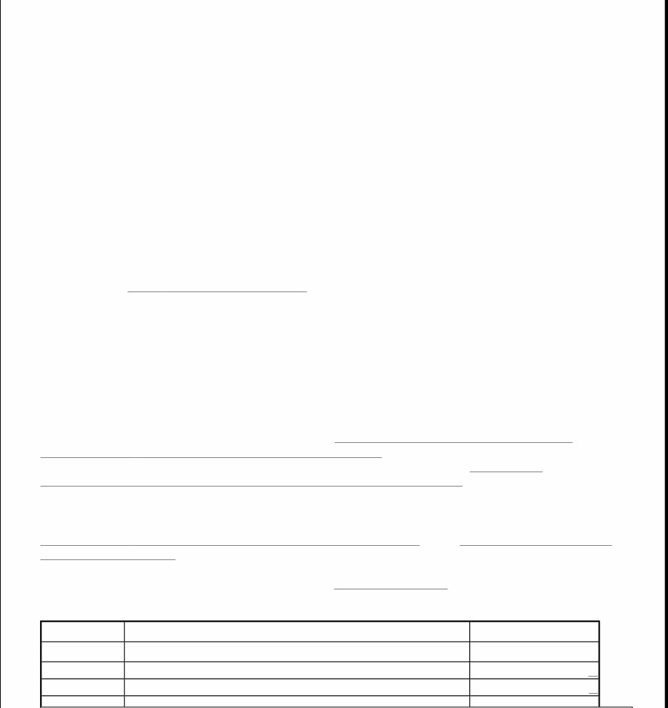
2. Disconnect RAP module 22-pin connector C338. RAP module is located behind left rear quarter panel.
Using a voltmeter, measure voltage between ground and RAP module 22-pin connector C338 terminal
No. 12 (White/Light Blue wire). See Fig. 1 . If voltage is more than 10 volts, go to next step. If voltage is
10 volts or less, repair open in White/Light Blue wire between RAP module and engine compartment fuse
block. Retest system operation.
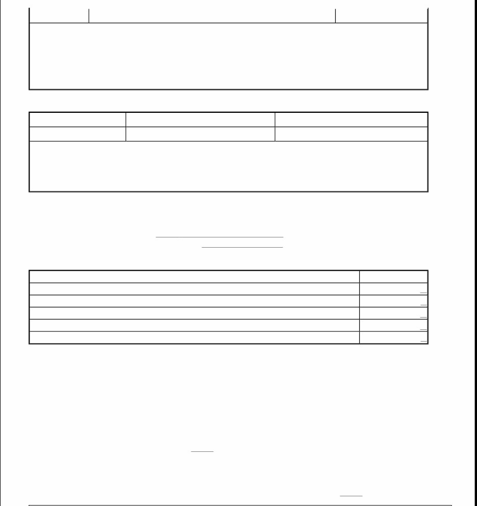
3. Disconnect RAP module 26-pin connector C336. Turn ignition on. Measure voltage between ground and
RAP module 26-pin connector C336 terminal No. 25 (Black/Pink wire). See Fig. 2 . If voltage is more
than 10 volts, go to next step. If voltage is 10 volts or less, repair open in Black/Pink wire between RAP
B1845 Anti-Theft Ignition Lock Switch Failure
(3)
(1)
Codes listed in this table are only for testing covered in this article. For complete DTC listing, see
MODULE COMMUNICATIONS NETWORK - EXPLORER & MOUNTAINEER article.
(2)
Using NGS tester, retrieve and record continuous DTCs. Clear all DTCs. Perform GEM self-test. If
DTC B1342 is retrieved again, replace GEM.
(3)
Disregard DTC B1845. This is an invalid DTC.
DTC
(1)
Description Perform Test
B1342 GEM Failure
(2)
(1)
Codes listed in this table are only for testing covered in this article. For complete DTC listing, see
MODULE COMMUNICATIONS NETWORK - EXPLORER & MOUNTAINEER article.
(2)
Using NGS tester, retrieve and record all DTCs. Perform GEM self-test. If DTC B1342 is retrieved
again, replace GEM.
Symptom Perform Test
No Communication With Remote Anti-Theft Personality (RAP) Module A
Alarm System Does Not Arm Or Disarm Properly B
Alarm System Does Not Operate Properly C
THEFT Indicator Is Always/Never On D
No Communication With Generic Electronic Module (GEM) E
Module and instrument panel fuse block. Retest system operation.
4. Turn ignition off. Measure resistance between ground and RAP module 22-pin connector C338 terminal
No. 14 (Black/White wire). See Fig. 1 . If resistance is less than 5 ohms, go to MODULE
COMMUNICATIONS NETWORK - EXPLORER & MOUNTAINEER article to continue diagnosis. If
resistance is 5 ohms or more, repair open in Black/White wire between RAP module and ground. Retest
system operation.
Fig. 1: Identifying RAP Module 22 - Pin Connector C338 Terminals
Courtesy of FORD MOTOR CO.
Fig. 2: Identifying RAP Module C336 & GEM C280 26 - Pin Connector Terminals
Courtesy of FORD MOTOR CO.
TEST B: ALARM SYSTEM DOES NOT ARM OR DISARM PROPERLY
1. Turn ignition off. Using New Generation Star (NGS) tester, retrieve and record continuous DTCs. Clear
DTCs. Perform Remote Anti-theft Personality (RAP) module and Generic Electronic Module (GEM)

self-tests. If RAP module DTC B1562 is retrieved, go to next step. If GEM DTCs B1833, B1834, or
B1836 is retrieved, repair door unlock switch circuit. See appropriate POWER DOOR LOCKS article. If
no DTCs are retrieved, go to step 7 .
2. Using NGS tester, select RAP PID DR_DARM from PID/DATA monitor menu. If PID value indicates
ACTIVE, go to next step. If PID value does not indicate ACTIVE, repeat RAP module self-test.
3. Turn ignition off. Disconnect RAP module 26-pin connector C336. RAP module is located behind left
rear quarter panel. Disconnect GEM 26-pin connector C280. GEM is located behind center of instrument
panel. Using an ohmmeter, measure resistance between ground and RAP module 26-pin connector C336
terminal No. 9 (Dark Green/Purple wire). See Fig. 2 . If resistance is 10 k/ohms or less, go to next step. If
resistance is more than 10 k/ohms, replace RAP module. Clear DTCs and retest system operation.
4. Ensure key is not in driver's door lock cylinder. Disconnect driver's door disarm switch connector C510.
Driver's door disarm switch is located in rear of driver's door. Using an ohmmeter, measure resistance
between driver's door disarm switch connector C510 Dark Green/Purple wire terminal and Black wire
terminal (component side). If resistance is 200 ohms or more, go to next step. If resistance is less than
200 ohms, replace driver door disarm switch. Clear DTCs and retest system operation.
5. Ensure key is not in passenger's door lock cylinder. Disconnect passenger's door disarm switch connector
C607. Passenger's door disarm switch is located in rear of passenger's door. Using an ohmmeter, measure
resistance between passenger's door disarm switch connector C607 Dark Green/Purple wire terminal and
Black wire terminal (component side). If resistance is 200 ohms or more, go to next step. If resistance is
less than 200 ohms, replace passenger door disarm switch. Clear DTCs and retest system operation.
6. Ensure key is not in liftgate lock cylinder. Disconnect liftgate disarm switch connector C426. Liftgate
disarm switch is located near liftgate lock cylinder. Using an ohmmeter, measure resistance between
liftgate disarm switch connector C426 Dark Green/Purple wire terminal and Black wire terminal
(component side). If resistance is less than 200 ohms, replace liftgate disarm switch. Clear DTCs and
retest system operation. If resistance is 200 ohms or more, repair Dark Green/Purple wire between liftgate
disarm switch and RAP module. Clear DTCs and retest system operation.
7. Ensure ignition is off. Press driver's side door lock switch to LOCK and UNLOCK position. Use key to
lock and unlock driver's door. If door locks operate properly, go to next step. If door locks do not operate
properly, repair power door locks as necessary. See appropriate POWER DOOR LOCKS article.
8. Press LOCK and UNLOCK button on keyless entry remote transmitter. If door locks operate properly, go
to next step. If door locks do not operate properly, repair remote keyless entry system as necessary. See
appropriate REMOTE KEYLESS ENTRY SYSTEMS article.
9. Press 7/8 and 9/0 buttons on keyless entry keypad to lock doors. Enter 5-digit unlock code on keyless
entry keypad to unlock driver's door. If door locks operate properly, go to next step. If door locks do not
operate properly, repair remote keyless entry system as necessary. See appropriate REMOTE KEYLESS
ENTRY SYSTEMS article.
10. Open driver's door window. Arm system by pressing LOCK button on keyless entry remote transmitter.
Wait at least 30 seconds after all doors are closed and locked. Reach through window and open door to
trigger alarm system. If system does not trigger, go to next step. If system triggers, system is operating
properly. Verify concern with customer.
11. Using NGS tester, select RAP PID DOORRAP from PID/DATA monitor menu. Monitor PID while
opening and closing driver's door. If PID value indicates AJAR when door is opened and CLOSED when
door is closed, go to step 17 . If PID value only indicates AJAR, go to next step. If PID value only
indicates CLOSED, go to step 14 .
12. Turn ignition on. Using NGS tester, perform GEM self-test. If no DTCs are retrieved, go to next step. If

GEM DTC B1322, B1330, B1334, B1338, or B1574 is retrieved, repair appropriate circuit. See
MODULE COMMUNICATIONS NETWORK - EXPLORER & MOUNTAINEER article for
description of codes.
13. Turn ignition off. Disconnect RAP module 26-pin connector C336. RAP module is located behind left
rear quarter panel. Disconnect GEM 16-pin connector C281. GEM is located behind center of instrument
panel. Close all doors. Using an ohmmeter, measure resistance between ground and RAP module 26-pin
connector C336 terminal No. 11 (Light Blue/White wire). See Fig. 2 . If resistance is 10 k/ohms or less,
repair short to ground in Light Blue/White wire between RAP module and GEM. Clear DTCs and retest
system operation. If resistance is more than 10 k/ohms, replace RAP module. Clear DTCs and retest
system operation.
14. Using NGS tester, monitor GEM D_DR_SW PID while opening and closing driver's door. Monitor GEM
P_DR_SW PID while opening and closing passenger's door. Monitor GEM LRDR_SW PID while
opening and closing left rear door. Monitor RRDR_SW GEM PID while opening and closing right rear
door. Monitor GEM LGATE_SW PID while opening and closing liftgate. If all GEM PID values indicate
OPEN when doors are opened and CLOSED when doors are closed, go to next step. If any GEM PID
value does not indicate OPEN when doors are opened and CLOSED when doors are closed, repair
appropriate open or shorted door ajar circuit. See ILLUMINATION/INTERIOR LIGHTS article.
15. Turn ignition off. Disconnect RAP module 26-pin connector C336. RAP module is located behind left
rear quarter panel. Open driver's door. Measure resistance between ground and RAP module 26-pin
connector C336 terminal No. 11 (Light Blue/White wire). See Fig. 2 . If resistance is 5 ohms or more, go
to next step. If resistance is less than 5 ohms, replace RAP module. Clear DTCs and retest system
operation.
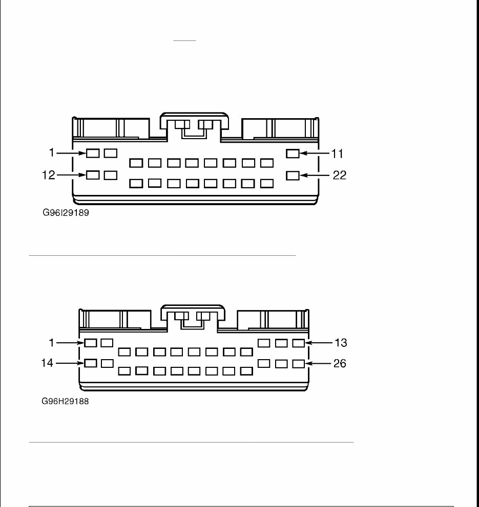
16. Disconnect GEM 16-pin connector C281. GEM is located behind center of instrument panel. Measure
resistance in Light Blue/White wire between RAP module 26-pin connector C336 terminal No. 11 and
GEM 16-pin connector C281 terminal No. 3. See Fig. 2 and Fig. 3 . If resistance is less than 5 ohms,
replace GEM. Clear DTCs and retest system operation. If resistance is 5 ohms or more, repair open Light
Blue/White wire between RAP module and GEM. Clear DTCs and retest system operation.
17. Using NGS tester, select RAP PID IGN_RAP from PID/DATA monitor menu. Monitor PID value while
turning ignition off to on. If PID value indicates RUN with ignition on and OFF with ignition off, go to
step 20 . If PID value indicates OFF only, go to step 19 . If PID value indicates RUN only, go to next
step.
18. Turn ignition off. Disconnect RAP module 26-pin connector C336. RAP module is located behind left
rear quarter panel. Remove instrument panel fuse block fuse No. 20 (7.5-amp). Turn ignition on. Using a
voltmeter, measure voltage between ground and RAP module 26-pin connector C336 terminal No. 25
(Black/Pink wire). If any voltage is present, repair short to power in Black/Pink wire between instrument
panel fuse block fuse No. 20 and RAP module. Clear DTCs and retest system operation. If no voltage is
present, replace RAP module. Clear DTCs and retest system operation.
19. Turn ignition off. Disconnect RAP module 26-pin connector C336. Turn ignition on. Using a voltmeter,
measure voltage between ground and RAP module 26-pin connector C336 terminal No. 25 (Black/Pink
wire). See Fig. 2 . If voltage is more than 10 volts, replace RAP module. Clear DTCs and retest system
operation. If voltage is 10 volts or less, repair Black/Pink wire between instrument panel fuse block fuse
No. 20 (7.5-amp) and RAP module. Retest system operation.
Fig. 3: Identifying GEM 16 - Pin Connector C281 Terminals
Courtesy of FORD MOTOR CO.
20. Using NGS tester, select RAP PID DR_DARM from PID/DATA monitor menu. Monitor PID value
while locking and unlocking doors. If PID value indicates notACT when doors are unlocked and
ACTIVE when doors are locked, go to step 25 . If PID value only indicates ACTIVE, go to step 2 . If PID
value only indicates notACT, go to next step.
21. Disconnect RAP module 26-pin connector C336. RAP module is located behind left rear quarter panel.
Using an ohmmeter, measure resistance between ground and RAP module 26-pin connector C336
terminal No. 9 (Dark Green/Purple wire) while turning driver's door lock cylinder to UNLOCK position.
See Fig. 2 . If resistance is less than 200 ohms, go to next step. If resistance is 200 ohms or more, replace
driver's door disarm switch. Clear DTCs and retest system operation.
22. Measure resistance between ground and RAP module 26-pin connector C336 terminal No. 9 (Dark
Green/Purple wire) while turning passenger's door lock cylinder to UNLOCK position. If resistance is
less than 200 ohms, go to next step. If resistance is 200 ohms or more, replace passenger's door disarm
switch. Clear DTCs and retest system operation.
23. Measure resistance between ground and RAP module 26-pin connector C336 terminal No. 9 (Dark
Green/Purple wire) while turning liftgate door lock cylinder to UNLOCK position. If resistance is less
than 200 ohms, go to next step. If resistance is 200 ohms or more, replace liftgate disarm switch. Clear
DTCs and retest system operation.
24. Disconnect driver's door disarm switch connector C510. Driver's door disarm switch is located in rear of
NOTE: If RAP module receives a shorted door disarm switch signal, module will
react by disarming anti-theft system. Even when valid arming sequence
has been entered, anti-theft system will disarm as soon as system is
armed.

driver's door. Using an ohmmeter, measure resistance of Dark Green/Purple wire between RAP module
26-pin connector C336 terminal No. 9 and driver's door disarm switch connector C510. If resistance is
less than 5 ohms, replace RAP module. Clear DTCs and retest system operation. If resistance is 5 ohms or
more, repair open in Dark Green/Purple wire between driver's door disarm switch and RAP module. Clear
DTCs and retest system operation.
25. Using NGS tester, RAP PID select DD_LOCK from PID/DATA monitor menu. Monitor PID while
pressing lock and unlock switches on driver's and passenger's doors. If PID value indicates LOCK when
lock switches are pressed and UNLOCK when unlock switches are pressed, RAP module is operating
properly. Clarify concern with customer. If PID value indicates only UNLOCK, go to next step. If PID
value indicates only LOCK, go to step 27 .
26. This check must be done within 2.5 seconds of triggering active command to ON. Backprobing connector
with ohmmeter, measure resistance between RAP module 22-pin connector C338 terminal No. 22
(Pink/Yellow wire) and ground while triggering RAP active command DOOR LOCK CONTROL LOCK
to ON. See Fig. 1 . If resistance is more than 10 k/ohms, replace RAP module. Clear DTCs and retest
system operation. If resistance is 10 k/ohms or less, repair short to ground in Pink/Yellow wire between
door lock control switch and RAP module. Clear DTCs and retest system operation.
27. This check must be done within 2.5 seconds of triggering active command to ON. Backprobing connector
with ohmmeter, measure resistance between RAP module 22-pin connector C338 terminal No. 11
(Pink/Light Green wire) and ground while triggering RAP active command DOOR LOCK CONTROL
UNLOCK to ON. See Fig. 1 . If resistance is more than 10 k/ohms, replace RAP module. Clear DTCs
and retest system operation. If resistance is 10 k/ohms or less, repair short to ground in Pink/Light Green
wire between door lock control switch and RAP module. Clear DTCs and retest system operation.
TEST C: ALARM SYSTEM DOES NOT OPERATE PROPERLY
1. Turn ignition off. Using New Generation Star (NGS) tester, retrieve and document continuous DTCs.
Clear DTCs. Perform Remote Anti-Theft Personality (RAP) module self-test. If DTC B1522 is retrieved,
go to next step. If DTC B1522 is not retrieved, go to step 5 . If DTC B1845 is retrieved, disregard this
DTC. This is an invalid DTC.
2. Using NGS tester, select RAP PID HOOD_SW from PID/DATA monitor menu. Monitor PID value with
hood closed. If PID value indicates PUNCHD, go to next step. If PID value does not indicate PUNCHD,
repeat RAP module self-test.
3. Turn ignition off. Disconnect RAP module 26-pin connector C336. RAP module is located behind left
rear quarter panel. Using an ohmmeter, measure resistance between ground and RAP module 26-pin
connector C336 terminal No. 23 (Tan/Light Green wire). See Fig. 2 . If resistance is 10 k/ohms or less, go
to next step. If resistance is more than 10 k/ohms, replace RAP module. Clear DTCs and retest system
NOTE: If RAP system module received an all door unlock signal shorted, RAP
module will react by disarming anti-theft system. Even when valid arming
sequence has been entered, anti-theft system will immediately disarm.
NOTE: DTC B1522 will be stored during operational mode if hood is open for 5
consecutive arming cycles. DTC B1522 is stored during RAP module self-
test if hood is open at that time.

operation.
4. Disconnect anti-theft hood switch connector C191. Connector C191 is located on upper right fender
apron. Using an ohmmeter, measure resistance between anti-theft hood switch Tan/Light Green wire
terminal and Black wire terminal (component side) while depressing anti-theft hood switch plunger. If
resistance is 10 k/ohms or less, replace anti-theft hood switch. Clear DTCs and retest system operation. If
resistance is more than 10 k/ohms, verify anti-theft hood switch is mounted correctly so plunger is
depressed when hood is closed. If hood switch is mounted correctly, repair Tan/Light Green wire between
RAP module and anti-theft hood switch. Clear DTCs and retest system operation.
5. Arm anti-theft system by pressing lock button on remote entry transmitter. Trigger alarm. If alarm
operates properly, RAP system is operating properly. Verify concern with customer. If horn does not
sound, go to next step. If parking lights do not illuminate, go to step 8 . If concern is false system
activation, go to step 10 .
6. Press steering wheel horn pad switch. If horn operates properly, go to next step. If horn does not operate
properly, repair horn system. See WIRING DIAGRAMS in STEERING COLUMN SWITCHES -
EXPLORER & MOUNTAINEER article to continue diagnosis.
7. Turn ignition off. Disconnect RAP module 22-pin connector C338. Remove horn relay, from engine
compartment fuse block. Using an ohmmeter, measure resistance of Yellow/Light Green wire between
RAP module 22-pin connector C338 terminal No. 20 and horn relay connector terminal No. 2. See Fig. 1
and Fig. 4 . Measure resistance between ground and horn relay connector terminal No. 2 (Yellow/Light
Green wire). If resistance of Yellow/Light Green wire is less than 5 ohms between RAP module 22-pin
connector C338 and horn relay, and more than 10 k/ohms between horn relay and ground, replace RAP
module and retest system operation. If resistance in Yellow/Light Green wire is 5 ohms or more between
RAP module 22-pin connector C338 and horn relay, or 10 k/ohms or less between horn relay and ground,
repair open or short to ground in Yellow/Light Green wire between RAP module and horn relay. Retest
system operation.
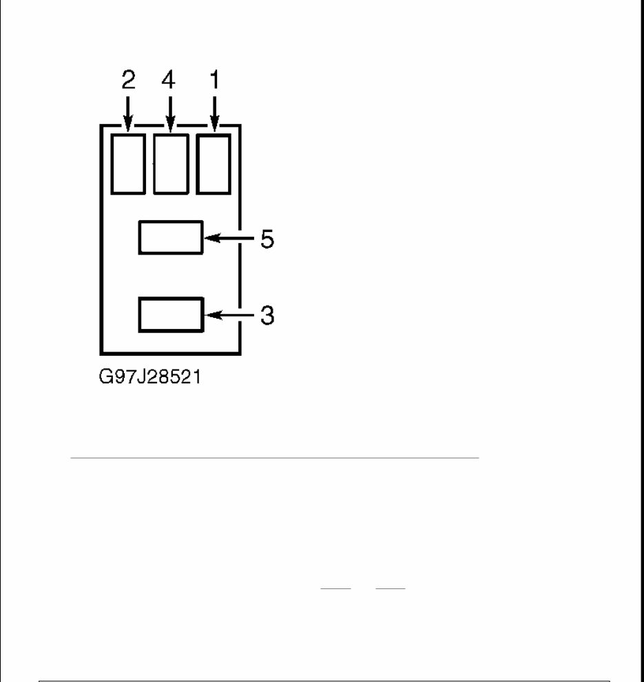
Fig. 4: Identifying Horn Relay & Parking Light Relay Connector Terminals
Courtesy of FORD MOTOR CO.
8. Turn headlight switch to parking lights position. If parking lights operate properly, go to next step. If
parking lights do not operate properly, repair parking lights as necessary. See EXTERIOR LIGHTS
article.
9. Turn ignition off. Disconnect RAP module 22-pin connector C338. Remove parking light relay. Parking
light relay is located behind lower instrument panel on right of steering column. Using an ohmmeter,
measure resistance in White/Purple wire between RAP module 22-pin connector C338 terminal No. 8 and
parking light relay connector terminal No. 2. See Fig. 1 and Fig. 4 . Measure resistance between ground
and parking light relay connector terminal No. 2 (White/Purple wire). If resistance in White/Purple wire
is less than 5 ohms between RAP module 22-pin connector C338 and parking light relay, and more than
10 k/ohms between horn relay and ground, replace RAP module and retest system operation. If resistance
in White/Purple wire is 5 ohms or more between RAP module 22-pin connector C338 and parking light
relay, or 10 k/ohms or less between parking light relay and ground, repair open or short to ground in
White/Purple wire between RAP module and parking light relay. Retest system operation.
You're Reading a Preview
What's Included?
Fast Download Speeds
Online & Offline Access
Access PDF Contents & Bookmarks
Full Search Facility
Print one or all pages of your manual
$31.99
Viewed 34 Times Today


Secure transaction
What's Included?
Fast Download Speeds
Online & Offline Access
Access PDF Contents & Bookmarks
Full Search Facility
Print one or all pages of your manual
$31.99
The 2000 Ford Explorer Repair Manual is a comprehensive guide designed to assist in maintaining and repairing your Ford Explorer. Whether you are a professional mechanic or a DIY enthusiast, this manual provides detailed instructions and illustrations to help troubleshoot and fix any issues with your vehicle.
Features:
- Provides step-by-step instructions for all repair procedures
- Includes detailed diagrams and illustrations to guide through the repair process
- Covers all models of the 2000 Ford Explorer
This repair manual enables you to save time and money by performing the repairs yourself. It covers a wide range of tasks, from basic maintenance to complex engine repairs, including information on the engine, transmission, electrical system, suspension, brakes, and more.
Invest in the 2000 Ford Explorer Repair Manual today to ensure the smooth operation of your vehicle for years to come.


