

2003-2006 Ford Expedition SUV Service & Repair Manual
What's Included?
Fast Download Speeds
Offline Viewing
Access Contents & Bookmarks
Full Search Facility
Print one or all pages of your manual

2004 TRANSMISSION
Four-Wheel Drive Systems - Expedition And Navigator
DESCRIPTION AND OPERATION
FOUR-WHEEL DRIVE SYSTEMS
The automatic 4-wheel drive transfer case system consists of the following:
Automatic 4WD indicator light
Brake pedal position (BPP) switch
Integrated wheel ends (IWE) solenoid
Torque on demand (TOD) relay
4WD control module
4WD high indicator light
4WD low indicator light
4WD mode select switch (MSS)
Shift position sensor
Throttle position output (TPO) from the powertrain control module (PCM)
Transmission range sensor
Average front and rear wheel speed signals from the anti-lock brake system
DIAGNOSIS AND TESTING
FOUR-WHEEL DRIVE SYSTEMS
Refer to SYSTEM WIRING DIAGRAMS (Navigator) or SYSTEM WIRING DIAGRAMS (Expedition) for
schematic and connector information.
2004 Lincoln Navigator
2004 TRANSMISSION Four-Wheel Drive Systems - Expedition And Navigator
2004 Lincoln Navigator
2004 TRANSMISSION Four-Wheel Drive Systems - Expedition And Navigator
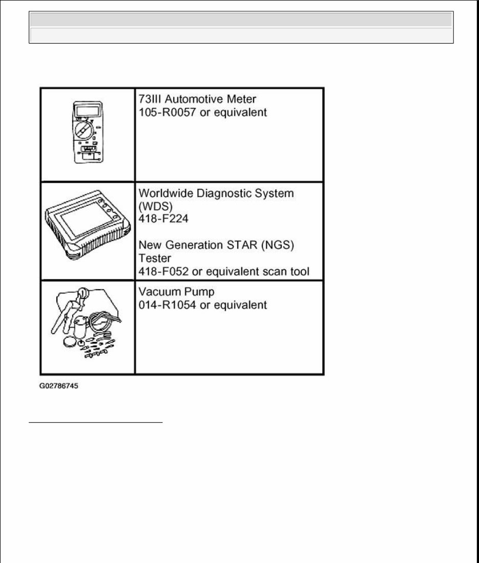
Fig. 1: Identifying Special Tool(s)
Courtesy of FORD MOTOR CO.
Principles of Operation
2004 Lincoln Navigator
2004 TRANSMISSION Four-Wheel Drive Systems - Expedition And Navigator
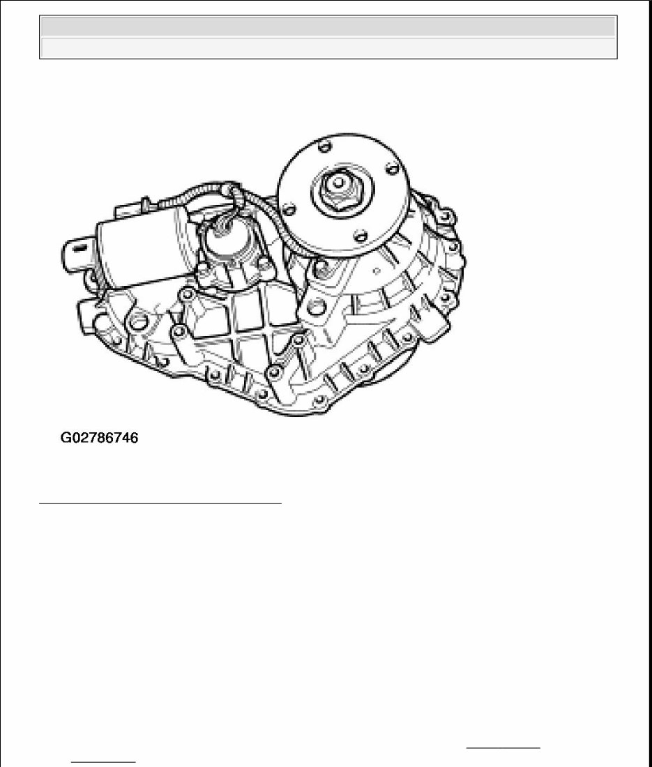
Fig. 2: Identifying Four Wheel Drive System
Courtesy of FORD MOTOR CO.
The automatic four-wheel drive (A4WD) system is an electronic-shift 4WD system that allows the operator to
choose between 2WD and three different 4WD modes. The operator can switch between A4WD and 4WD
HIGH modes at any speed. To engage or disengage 4WD LOW range, the vehicle speed must be less than 5
km/h (3.1 mph), the brake pedal must be pressed and the transmission must be in NEUTRAL.
Wheel slip is sensed using one axle shaft speed sensor on each axle. Based on throttle position and wheel slip, a
pulse width modulated (PWM) signal is transmitted to the transfer case clutch when a predetermined slip-
threshold is exceeded.
The 4WD control module will provide the IVD brake system with current clutch duty cycle and whether or not
IVD may command the clutch duty cycle.
The brake subsystem sends the following information signals to the 4WD system:
Occurrences of brake events and failures (for additional information, refer to ANTI - LOCK
CONTROL ).
2004 Lincoln Navigator
2004 TRANSMISSION Four-Wheel Drive Systems - Expedition And Navigator

Steering wheel angle status (for additional information, refer to ANTI - LOCK CONTROL ).
Average rear wheel speed (for additional information, refer to ANTI - LOCK CONTROL ).
Average front wheel speed (for additional information, refer to ANTI - LOCK CONTROL ).
Delta front wheel speeds (for additional information, refer to ANTI - LOCK CONTROL ).
A concern with any of the above listed brake system signals will affect operation of the 4WD system.
The throttle position output signal is provided to the 4WD control module from the powertrain control module
(PCM). This signal is used by the 4WD control module in controlling the 4WD clutch.
The shift motor sense plate, an integral part of the gear motor encoder assembly, informs the 4WD control
module of the transfer case position.
The digital transmission range (TR) sensor is located on the LH side of the transmission. This sensor informs
the 4WD control module when the transmission is in NEUTRAL.
The electric shift motor is mounted externally to the gear motor encoder assembly at the rear of the transfer
case. It drives a rotary cam which moves the mode fork and range fork within the transfer case between the
HIGH range (A4WD, 4WD HIGH) and 4WD LOW range positions.
The 4WD shift motor is controlled by the 4WD control module which shifts the transfer case shift motor
between HIGH range (A4WD, 4WD HIGH), and 4WD LOW modes.
The solid-state clutch is duty-cycled by the 4WD control module to activate the 4WD clutch within the transfer
case.
In the A4WD system, the 4WD control module varies the torque sent to the front driveline by controlling the
transfer case clutch. At rest and under cruising conditions, the 4WD control module activates the transfer case
clutch a minimum duty cycle (percentage of time the clutch is turned on), which allows for the slight difference
between the front and rear driveshafts which normally occurs when negotiating a corner on dry pavement.
Under any of the following conditions, the 4WD control module will increase the duty cycle in order to prevent
or control slip:
Slip is detected
Heavy acceleration (throttle position)
Feature inputs:
Brake ON/OFF switch
Mode select switch (MSS)
Digital TR sensor (automatic transmission only)
Vehicle speed signal (transmitted from the ABS module)
Front and rear driveshaft speed sensors
Throttle position information (transmitted from the PCM)
2004 Lincoln Navigator
2004 TRANSMISSION Four-Wheel Drive Systems - Expedition And Navigator

Gear motor encoder contact plate position inputs A, B, C, D
Feature outputs:
Solid state clutch (pulse width modulated signal)
4WD LOW indicator
4WD shift motor outputs
Shifts between A4WD and 4WD HIGH can be made at any speed. Listed below are the inputs and outputs
needed by the 4WD control module to execute a change between any of these modes.
Feature inputs:
Front and rear driveshaft speed sensors
Vehicle speed signal
Throttle position information
4WD Mode Select Switch (MSS)
Feature outputs:
Solid state clutch (pulse width modulated signal)
4WD HIGH switch indicator
When shifting into or out of LOW range, the 4WD control module requires that the vehicle speed is less than 5
km/h (3 mph), the brake is applied, and the transmission is in NEUTRAL.
Feature inputs:
Throttle position information (transmitted from PCM)
MSS
Gear motor encoder contact plate position inputs A, B, C, D
Vehicle speed signal (transmitted from ABS module)
Brake ON/OFF (BOO) switch input (battery voltage when brake pedal is depressed, open circuit when
not activated)
Digital TR sensor (ground when transmission is in NEUTRAL, open circuit otherwise)
Feature outputs:
4WD shift motor outputs
4WD LOW switch indicator
Solid state clutch (pulse width modulated signal)
Inspection and Verification
2004 Lincoln Navigator
2004 TRANSMISSION Four-Wheel Drive Systems - Expedition And Navigator
1. Verify the customer concern.
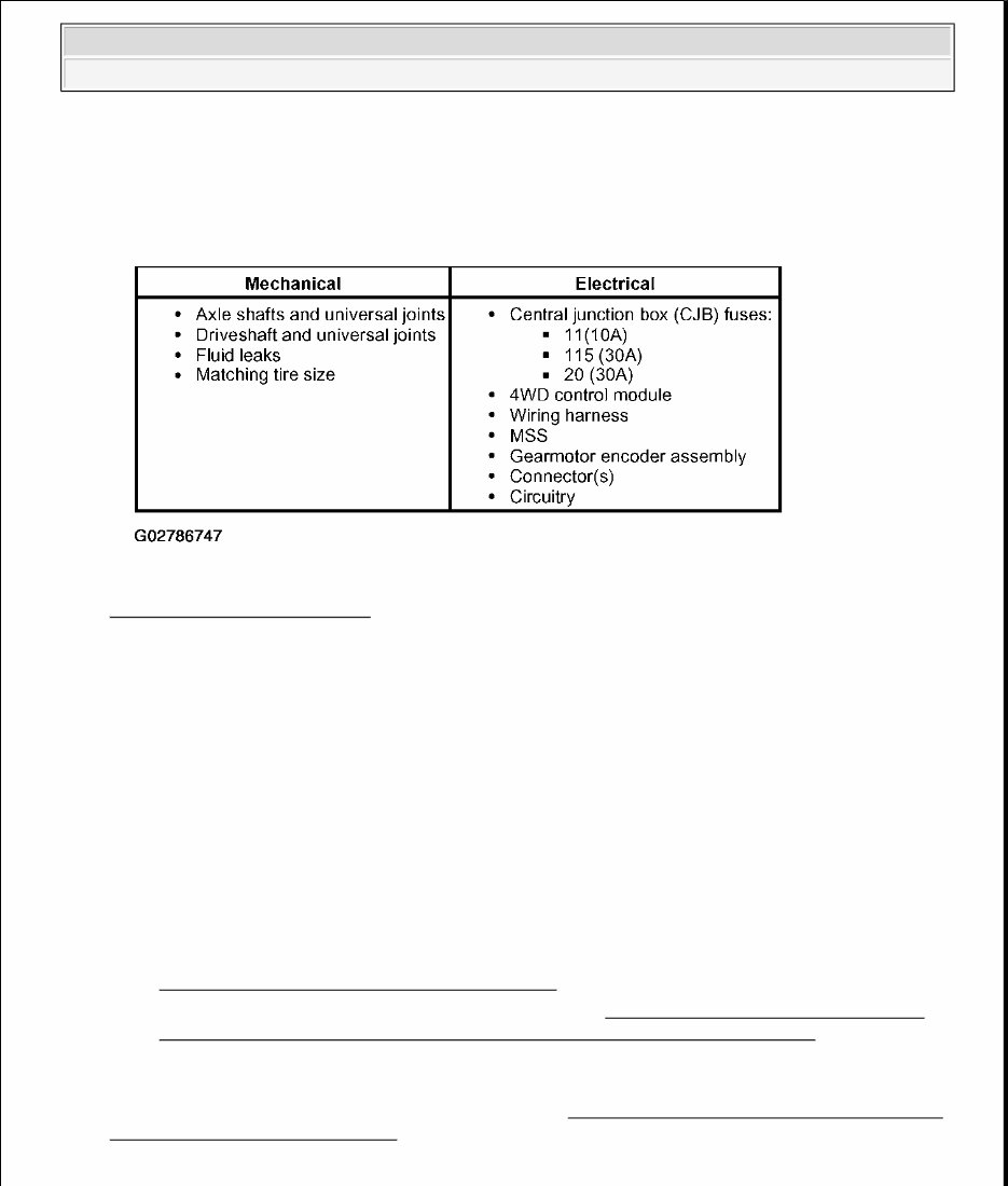
2. Visually inspect for obvious signs of mechanical or electrical damage.
Fig. 3: Visual Inspection Chart
Courtesy of FORD MOTOR CO.
3. If an obvious cause for an observed or reported concern is found, correct the cause (if possible) before
proceeding to the next step.
4. If the cause is not visually evident, connect the diagnostic tool to the data link connector (DLC) located
beneath the instrument panel and select the vehicle to be tested from the diagnostic tool menu. If the
diagnostic tool does not communicate with the vehicle:
Check that the program card is correctly installed.
Check the connections to the vehicle.
Check the ignition switch position.
5. If the diagnostic tool still does not communicate with the vehicle, refer to the diagnostic tool operating
manual.
6. Carry out the DATA LINK DIAGNOSTICS test. If the diagnostic tool responds with:
CKT930, CKT914, CKT 915 and CKT70= ALL ECUS NO RESP/NOT EQUIP, refer to
MODULE COMMUNICATIONS NETWORK .
NO RESP/NOT EQUIP for 4WD control module, go to PINPOINT TEST B: THE VEHICLE
DOES NOT OPERATE CORRECTLY IN A4WD AND 4WD HIGH MODES .
SYSTEM PASSED, retrieve and record the continuous diagnostic trouble codes (DTCs), erase the
continuous DTCs and carry out the 4WD control module self-test.
7. If the DTCs retrieved are related to the concern, go to the 4WD CONTROL MODULE DIAGNOSTIC
TROUBLE CODE (DTC) INDEX to continue diagnostics.
4WD Control Module Diagnostic Trouble Code (DTC) Index
2004 Lincoln Navigator
2004 TRANSMISSION Four-Wheel Drive Systems - Expedition And Navigator
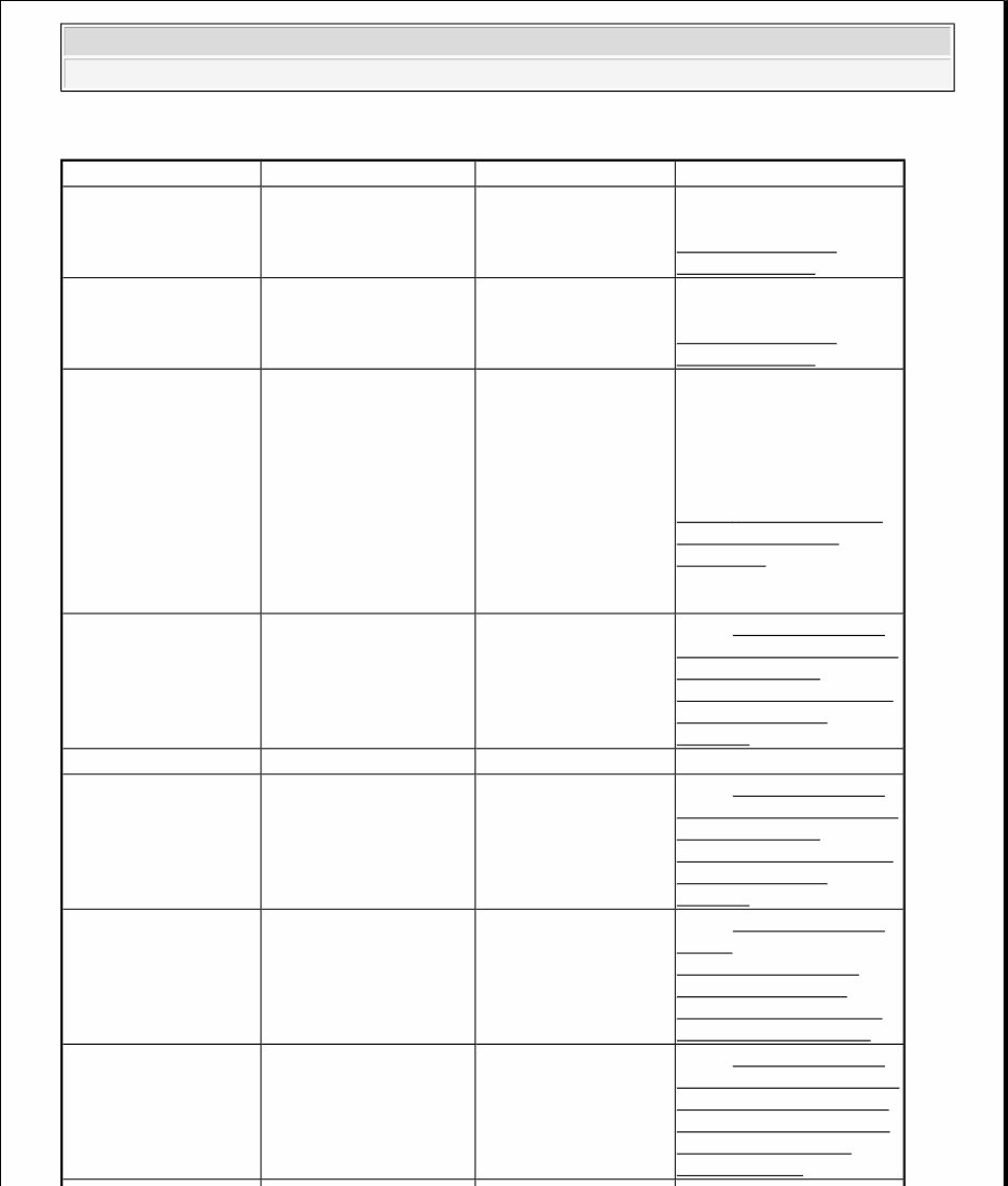
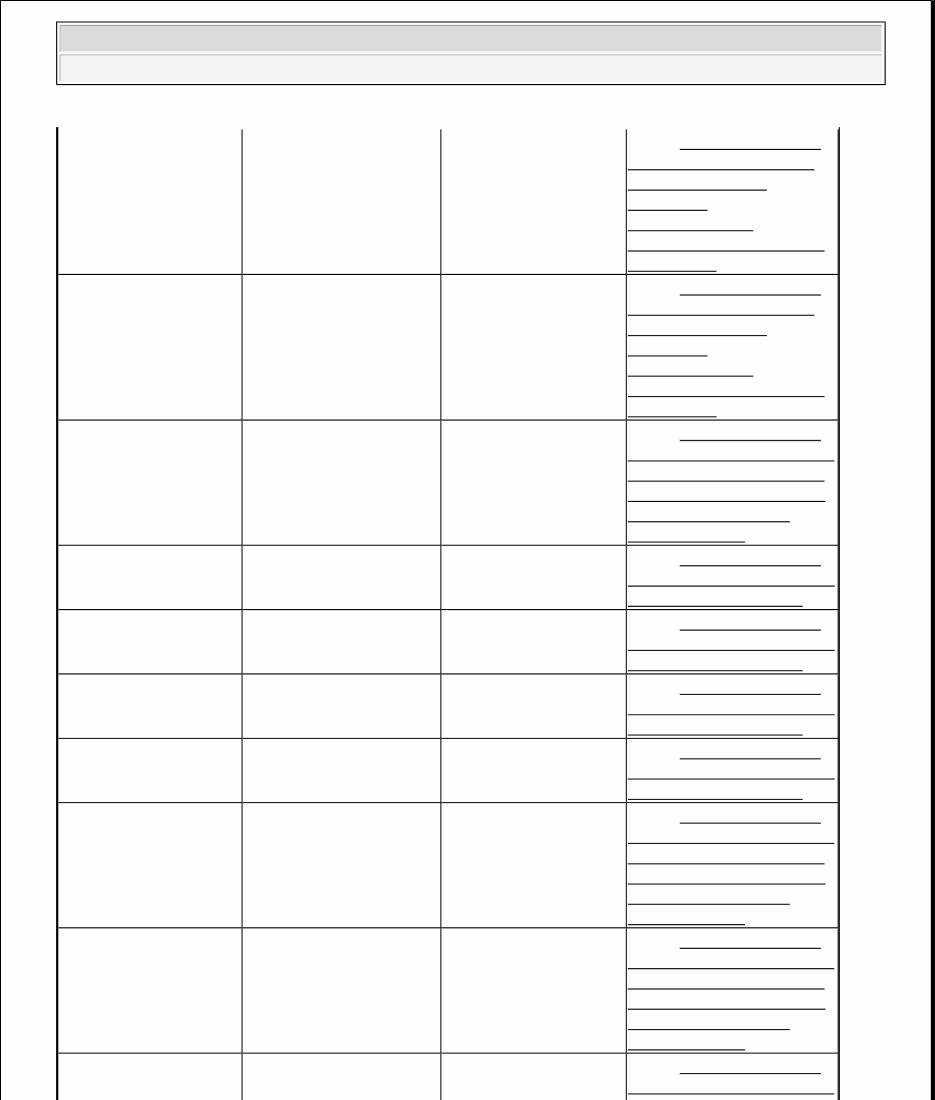
4WD CONTROL MODULE DIAGNOSTIC TROUBLE CODE INDEX
DTC Description Source Action
B1317 Battery Voltage High 4WD control module CHECK the battery and
charging system. REFER to
GENERATORS &
REGULATORS .
B1318 Battery Voltage Low 4WD control module CHECK the battery and
charging system, REFER to
GENERATORS &
REGULATORS .
B1342 ECU is Defective 4WD control module CLEAR the DTCs.
REPEAT the 4WD control
module self-test. If DTC
B1342 is retrieved,
INSTALL a new 4WD
control module. REFER to
FOUR - WHEEL DRIVE
(4WD) CONTROL
MODULE . CLEAR the
DTCs. REPEAT the self-
test.
B2105 Throttle Position Input
Out
4WD Go To PINPOINT TEST
B: THE VEHICLE DOES
NOT OPERATE
CORRECTLY IN A4WD
AND 4WD HIGH
MODES .
- Of Range Low Control module -
B2106 Throttle Position Input
Out of Range High
4WD control module Go To PINPOINT TEST
B: THE VEHICLE DOES
NOT OPERATE
CORRECTLY IN A4WD
AND 4WD HIGH
MODES .
C1728 Transfer Case Unable to
Transition Between 2H
and 4H.
4WD control module Go To PINPOINT TEST
C: NO
COMMUNICATION
WITH THE FOUR -
WHEEL DRIVE (4WD)
CONTROL MODULE .
C1729 Transfer Case Unable to
Transition Between 4WD
HIGH and 4WD LOW
4WD control module Go To PINPOINT TEST
D: THE VEHICLE DOES
NOT SHIFT BETWEEN
AUTO/4WD HIGH AND
4WD LOW MODES
CORRECTLY .
2004 Lincoln Navigator
2004 TRANSMISSION Four-Wheel Drive Systems - Expedition And Navigator
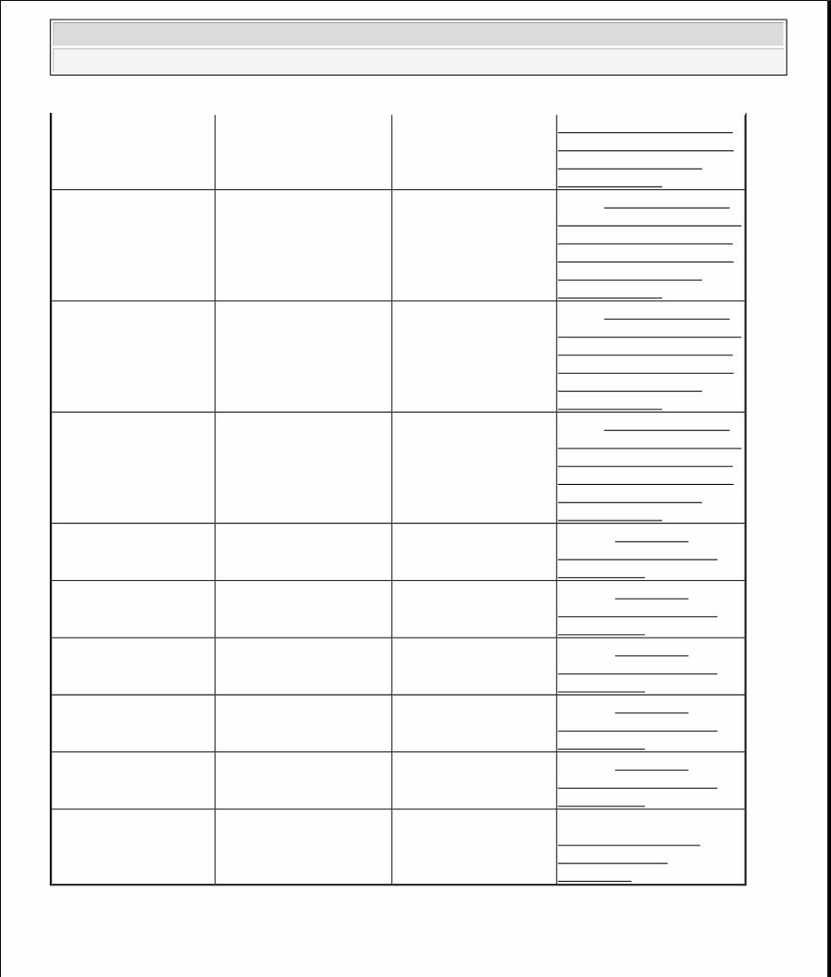
C1979 IWE Solenoid Circuit
Failure
4WD control module Go To PINPOINT TEST
F: DTCS C1979/C1980 -
IWE SOLENOID
CIRCUIT
FAILURE/IWE
SOLENOID SHORT TO
BATTERY .
C1980 IWE Solenoid Short to
Battery
4WD control module Go To PINPOINT TEST
F: DTCS C1979/C1980 -
IWE SOLENOID
CIRCUIT
FAILURE/IWE
SOLENOID SHORT TO
BATTERY .
P1812 Transmission 4-Wheel
Drive Mode Select Circuit
Failure
4WD control module Go To PINPOINT TEST
D: THE VEHICLE DOES
NOT SHIFT BETWEEN
AUTO/4WD HIGH AND
4WD LOW MODES
CORRECTLY .
P1815 Transmission 4-Wheel
Drive Mode Select Short
Circuit to Ground
4WD control module Go To PINPOINT TEST
A: ELECTRONIC SHIFT
FUNCTIONAL TEST .
P1824 Transmission 4-Wheel
Drive Clutch Relay
Circuit Failure
4WD control module Go To PINPOINT TEST
A: ELECTRONIC SHIFT
FUNCTIONAL TEST .
P1826 Transmission 4-Wheel
Drive Low Clutch Relay
Short Circuit to Battery
4WD control module Go To PINPOINT TEST
A: ELECTRONIC SHIFT
FUNCTIONAL TEST .
P1827 Transmission 4-Wheel
Drive Low Clutch Relay
Short Circuit to Ground
4WD control module Go To PINPOINT TEST
A: ELECTRONIC SHIFT
FUNCTIONAL TEST .
P1849 Transmission Transfer
Case Contact Plate A
Short Circuit to Ground
4WD control module Go To PINPOINT TEST
D: THE VEHICLE DOES
NOT SHIFT BETWEEN
AUTO/4WD HIGH AND
4WD LOW MODES
CORRECTLY .
P1853 Transmission Transfer
Case Contact Plate B
Short Circuit to Ground
4WD control module Go To PINPOINT TEST
D: THE VEHICLE DOES
NOT SHIFT BETWEEN
AUTO/4WD HIGH AND
4WD LOW MODES
CORRECTLY .
P1857 Transmission Transfer
Case Contact Plate C
4WD control module Go To PINPOINT TEST
D: THE VEHICLE DOES
2004 Lincoln Navigator
2004 TRANSMISSION Four-Wheel Drive Systems - Expedition And Navigator
Functional Test-Electronic Shift
PINPOINT TEST A: ELECTRONIC SHIFT FUNCTIONAL TEST
Short Circuit to Ground NOT SHIFT BETWEEN
AUTO/4WD HIGH AND
4WD LOW MODES
CORRECTLY .
P1861 Transmission Transfer
Case Contact Plate D
Short Circuit to Ground
4WD control module Go To PINPOINT TEST
D: THE VEHICLE DOES
NOT SHIFT BETWEEN
AUTO/4WD HIGH AND
4WD LOW MODES
CORRECTLY .
P1867 Transmission Transfer
Case Contact Plate
General Circuit Failure
4WD control module Go To PINPOINT TEST
D: THE VEHICLE DOES
NOT SHIFT BETWEEN
AUTO/4WD HIGH AND
4WD LOW MODES
CORRECTLY .
P1891 Transmission Transfer
Case Contact Plate
Ground Return Open
Circuit
4WD control module Go To PINPOINT TEST
D: THE VEHICLE DOES
NOT SHIFT BETWEEN
AUTO/4WD HIGH AND
4WD LOW MODES
CORRECTLY .
U1900 CAN Communication
BUS Fault
4WD control module Refer to MODULE
COMMUNICATIONS
NETWORK .
U1950 UBP Communication
BUS Fault
4WD control module Refer to MODULE
COMMUNICATIONS
NETWORK .
U2023 External Node Fault 4WD control module Refer to MODULE
COMMUNICATIONS
NETWORK .
U2306 Invalid UBP Data From
Instrument Cluster (Node
60)
4WD control module Refer to MODULE
COMMUNICATIONS
NETWORK .
U2226 Invalid UBP Data From
PCM (Node 10)
4WD control module Refer to MODULE
COMMUNICATIONS
NETWORK .
- For All Other DTCs 4WD control module REFER to
MULTIFUNCTION
ELECTRONIC
MODULE .
2004 Lincoln Navigator
2004 TRANSMISSION Four-Wheel Drive Systems - Expedition And Navigator
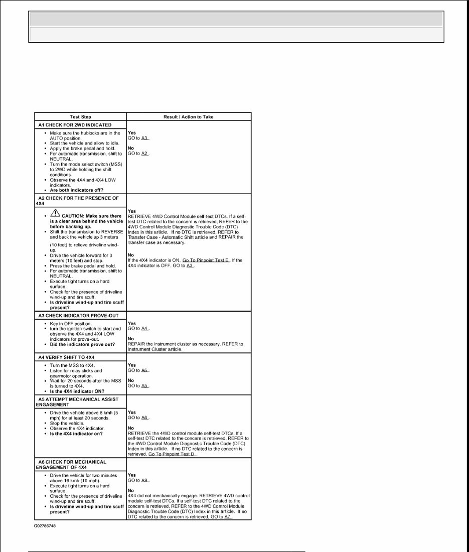
Fig. 4: Pinpoint Test A: Electronic Shift Functional Test (Steps A1 - A6)
CAUTION: The function test must be carried out on a hard surface in a vacant area
without traffic.
2004 Lincoln Navigator
2004 TRANSMISSION Four-Wheel Drive Systems - Expedition And Navigator
You're Reading a Preview
What's Included?
Fast Download Speeds
Offline Viewing
Access Contents & Bookmarks
Full Search Facility
Print one or all pages of your manual
$35.99
Viewed 12 Times Today


Secure transaction
What's Included?
Fast Download Speeds
Offline Viewing
Access Contents & Bookmarks
Full Search Facility
Print one or all pages of your manual
$35.99
The 2003-2006 Ford Expedition Service & Repair Manual is an essential guide specifically designed for the 2003, 2004, 2005, and 2006 Ford Expedition models. This manual provides detailed instructions, illustrations, and diagrams for servicing a wide range of components on your Ford Expedition, ensuring that all routine maintenance tasks as well as complex repairs are clearly explained.
Key features of the 2003-2006 Ford Expedition Service & Repair Manual:
- Comprehensive coverage for the 2003, 2004, 2005, and 2006 models
- Detailed instructions for common maintenance tasks such as oil changes, filter replacements, and fluid checks
- Step-by-step procedures for diagnosing and repairing engine, transmission, suspension, and electrical systems
- Illustrations and diagrams to simplify understanding of complex components and systems
- Troubleshooting tips and solutions to common service issues
- Specifications and technical data for precise and effective repairs
- Easy-to-use format for quick access to the necessary information
Improve the longevity and performance of your Ford Expedition with this detailed and practical service manual—an indispensable tool for both DIY enthusiasts and professional mechanics.


