

1980-1990 Ford Escort Service & Repair Manual
What's Included?
Fast Download Speeds
Online & Offline Access
Access PDF Contents & Bookmarks
Full Search Facility
Print one or all pages of your manual
Chapter 1
Routine maintenance and servicing
Air cleaner element renewal . . . . . . . . . . . . . . . . . . . . . . . . . . . . . . .34
Alternator drivebelt check . . . . . . . . . . . . . . . . . . . . . . . . . . . . . . . .20
Automatic transmission fluid level check . . . . . . . . . . . . . . . . . . . . .27
Automatic transmission selector mechanism check . . . . . . . . . . . .28
Battery check . . . . . . . . . . . . . . . . . . . . . . . . . . . . . . . . . . . . . . . . . . .5
Brake components check . . . . . . . . . . . . . . . . . . . . . . . . . . . . . . . .38
Brake fluid renewal . . . . . . . . . . . . . . . . . . . . . . . . . . . . . . . . . . . . . .39
Contact breaker points adjustment - models with contact
breaker distributor . . . . . . . . . . . . . . . . . . . . . . . . . . . . . . . . . . . .13
Contact breaker points renewal . . . . . . . . . . . . . . . . . . . . . . . . . . . .25
Coolant renewal . . . . . . . . . . . . . . . . . . . . . . . . . . . . . . . . . . . . . . . .33
Crankcase emission control filter renewal . . . . . . . . . . . . . . . . . . . .35
Distributor lubrication - models with contact breaker distributor . .12
Driveshaft check . . . . . . . . . . . . . . . . . . . . . . . . . . . . . . . . . . . . . . . .29
Engine oil and filter renewal . . . . . . . . . . . . . . . . . . . . . . . . . . . . . . . .6
Exhaust manifold nut check - RS Turbo models . . . . . . . . . . . . . . . .9
Exhaust system check . . . . . . . . . . . . . . . . . . . . . . . . . . . . . . . . . . .22
Fluid leak check . . . . . . . . . . . . . . . . . . . . . . . . . . . . . . . . . . . . . . . . .8
Fluid level checks . . . . . . . . . . . . . . . . . . . . . . . . . . . . . . . . . . . . . . . .3
Front brake disc pad check . . . . . . . . . . . . . . . . . . . . . . . . . . . . . . .16
Fuel filter renewal - fuel injection engines . . . . . . . . . . . . . . . . . . . .36
Hinge and lock check and lubrication . . . . . . . . . . . . . . . . . . . . . . .31
Idle speed and mixture adjustment . . . . . . . . . . . . . . . . . . . . . . . . .10
Ignition system components check . . . . . . . . . . . . . . . . . . . . . . . . .11
Ignition timing check - models with contact breaker distributor . . .14
Intensive maintenance . . . . . . . . . . . . . . . . . . . . . . . . . . . . . . . . . . . .2
Introduction . . . . . . . . . . . . . . . . . . . . . . . . . . . . . . . . . . . . . . . . . . . .1
Manual transmission oil level check . . . . . . . . . . . . . . . . . . . . . . . . .26
Oil filler cap cleaning - OHV and HCS engines . . . . . . . . . . . . . . . . .7
Rear brake shoe lining check . . . . . . . . . . . . . . . . . . . . . . . . . . . . . .17
Road test . . . . . . . . . . . . . . . . . . . . . . . . . . . . . . . . . . . . . . . . . . . . .32
Roadwheel check . . . . . . . . . . . . . . . . . . . . . . . . . . . . . . . . . . . . . . .30
Seat belt check . . . . . . . . . . . . . . . . . . . . . . . . . . . . . . . . . . . . . . . . .19
Spark plug renewal . . . . . . . . . . . . . . . . . . . . . . . . . . . . . . . . . . . . . .24
Spark plug renewal - RS Turbo models . . . . . . . . . . . . . . . . . . . . . .15
Suspension and steering check . . . . . . . . . . . . . . . . . . . . . . . . . . . .18
Timing belt renewal . . . . . . . . . . . . . . . . . . . . . . . . . . . . . . . . . . . . .37
Turbocharger-to-manifold nut check - RS Turbo models . . . . . . . .23
Tyre checks . . . . . . . . . . . . . . . . . . . . . . . . . . . . . . . . . . . . . . . . . . . .4
Valve clearance adjustment - OHV and HCS engines . . . . . . . . . . .21
1•1
Easy, suitable for
novice with little
experience
Fairly easy, suitable
for beginner with
some experience
Fairly difficult, suitable
for competent DIY
mechanic
Difficult, suitable for
experienced DIY
mechanic
Very difficult,
suitable for expert DIY
or professional
Degrees of difficulty
Contents
1

Engine
Oil filter type . . . . . . . . . . . . . . . . . . . . . . . . . . . . . . . . . . . . . . . . . . . . . . Champion C104
Valve clearances (cold):
OHV engines:
Inlet . . . . . . . . . . . . . . . . . . . . . . . . . . . . . . . . . . . . . . . . . . . . . . . . . 0.22 mm (0.008 in)
Exhaust . . . . . . . . . . . . . . . . . . . . . . . . . . . . . . . . . . . . . . . . . . . . . . 0.59 mm (0.023 in)
HCS engines:
Inlet . . . . . . . . . . . . . . . . . . . . . . . . . . . . . . . . . . . . . . . . . . . . . . . . . 0.22 mm (0.008 in)
Exhaust . . . . . . . . . . . . . . . . . . . . . . . . . . . . . . . . . . . . . . . . . . . . . . 0.32 mm (0.012 in)
Cooling system
Recommended antifreeze concentration . . . . . . . . . . . . . . . . . . . . . . . . 45% by volume
Fuel system
Idle speed:
Carburettor models:
All except Weber 2V TLDM carburettor . . . . . . . . . . . . . . . . . . . . . 750 to 850 rpm
Weber 2V TLDM carburettor . . . . . . . . . . . . . . . . . . . . . . . . . . . . . . 700 to 800 rpm
Bosch K-Jetronic fuel injection models . . . . . . . . . . . . . . . . . . . . . . . 750 to 850 rpm
Bosch KE-Jetronic fuel injection models:
1985 models . . . . . . . . . . . . . . . . . . . . . . . . . . . . . . . . . . . . . . . . . . 800 to 900 rpm
1986 models onwards . . . . . . . . . . . . . . . . . . . . . . . . . . . . . . . . . . . 920 to 960 rpm
Electronic Fuel Injection (EFI) models . . . . . . . . . . . . . . . . . . . . . . . . . 900 ± 50 rpm
Idle mixture CO content:
Bosch K-Jetronic fuel injection models . . . . . . . . . . . . . . . . . . . . . . . 1.0 to 1.5 %
Bosch KE-Jetronic fuel injection models:
1985 models . . . . . . . . . . . . . . . . . . . . . . . . . . . . . . . . . . . . . . . . . . 0.25 to 0.75%
1986 models onwards . . . . . . . . . . . . . . . . . . . . . . . . . . . . . . . . . . . 0.5 to 1.1%
Electronic Fuel Injection (EFI) models . . . . . . . . . . . . . . . . . . . . . . . . . 0.8 ± 0.25% (cooling fan running)
Air filter element type:
1.1 litre and 1.3 litre OHV engines . . . . . . . . . . . . . . . . . . . . . . . . . . . Champion W153
1.1 litre and 1.3 litre HCS engines . . . . . . . . . . . . . . . . . . . . . . . . . . . Champion W225
1.1 litre and 1.3 litre CVH engines . . . . . . . . . . . . . . . . . . . . . . . . . . . Champion W127
1.4 litre CVH engine:
Carburettor engines . . . . . . . . . . . . . . . . . . . . . . . . . . . . . . . . . . . . Champion W179
Central Fuel Injection (CFI) engines . . . . . . . . . . . . . . . . . . . . . . . . Champion W201
1.6 litre CVH engine (except XR3 models):
Up to 1986 . . . . . . . . . . . . . . . . . . . . . . . . . . . . . . . . . . . . . . . . . . . Champion W169
1986 to October 1988 . . . . . . . . . . . . . . . . . . . . . . . . . . . . . . . . . . . Champion W201
October 1988 on . . . . . . . . . . . . . . . . . . . . . . . . . . . . . . . . . . . . . . . Champion W226
1.6 litre CVH engine (XR3 models) . . . . . . . . . . . . . . . . . . . . . . . . . Champion W201
Ignition system
Contact breaker points gap:
Bosch distributor . . . . . . . . . . . . . . . . . . . . . . . . . . . . . . . . . . . . . . . . . 0.40 to 0.50 mm (0.016 to 0.02 in)
Lucas distributor . . . . . . . . . . . . . . . . . . . . . . . . . . . . . . . . . . . . . . . . . 0.40 to 0.59 mm (0.016 to 0.023 in)
Dwell angle (contact breaker ignition system) . . . . . . . . . . . . . . . . . . . . 48º to 52º
Ignition timing *:
OHV engines:
Up to 1984 (contact breaker) . . . . . . . . . . . . . . . . . . . . . . . . . . . . . . . 12º BTDC at idle speed
1984-on (contact breaker) and all electronic ignition . . . . . . . . . . . . . 6º BTDC at idle speed
CVH engines (all models) . . . . . . . . . . . . . . . . . . . . . . . . . . . . . . . . . . . . 12º BTDC at idle speed
* Note: Ignition timing on models with either a Distributorless Ignition Sytem (DIS) or a programmed ignition system (ESC) cannot be adjusted.
Refer to Chapter 5, Part B for further information.
Spark plugs:
Type:
OHV and HCS engines . . . . . . . . . . . . . . . . . . . . . . . . . . . . . . . . . . . . Champion RS9YCC or RS9YC
CVH engines:
Carburettor models . . . . . . . . . . . . . . . . . . . . . . . . . . . . . . . . . . . . . Champion RC7YCC or RC7YC
Bosch K-Jetronic fuel injection and
Electronic Fuel Injection (EFI) models . . . . . . . . . . . . . . . . . . . . . . . Champion C6YCC or RC6YC
Bosch KE-Jetronic fuel injection models . . . . . . . . . . . . . . . . . . . . Champion C61YC
Central Fuel Injection (CFI) models . . . . . . . . . . . . . . . . . . . . . . . . . Champion RC7YCC or RC7YC4
Electrode gap:
All except HCS and CFI models:
RS9YCC, RC7YCC, C6YCC spark plugs . . . . . . . . . . . . . . . . . . . . 0.8 mm (0.032 in)
RS9YC, RC7YC, RC6YC, . . . . . . . . . . . . . . . . . . . . . . . . . . . . . . . . 0.7 mm (0.028 in)
HCS and CFI models . . . . . . . . . . . . . . . . . . . . . . . . . . . . . . . . . . . . . 1.0 mm (0.039 in)
1•2 Servicing Specifications

Servicing Specifications 1•3
1
Brakes
Minimum front brake disc pad thickness . . . . . . . . . . . . . . . . . . . . . . . . 1.5 mm (0.06 in)
Minimum rear brake shoe lining thickness . . . . . . . . . . . . . . . . . . . . . . . 1.0 mm (0.04 in)
Tyres
Tyre pressures . . . . . . . . . . . . . . . . . . . . . . . . . . . . . . . . . . . . . . . . . . . . See “Weekly checks” on page 0•16
Torque wrench settings Nm lbf ft
Exhaust manifold nuts - RS Turbo models . . . . . . . . . . . . . . . . . . . . . . . 14 to 17 10 to 13
Turbocharger-to-manifold nuts . . . . . . . . . . . . . . . . . . . . . . . . . . . . . . . 21 to 26 15 to 19
Spark plugs:
OHV and HCS engines . . . . . . . . . . . . . . . . . . . . . . . . . . . . . . . . . . . . 13 to 20 10 to 15
CVH engines . . . . . . . . . . . . . . . . . . . . . . . . . . . . . . . . . . . . . . . . . . . . 25 to 38 18 to 28
Seat belt anchor bolts . . . . . . . . . . . . . . . . . . . . . . . . . . . . . . . . . . . . . . . 29 to 41 21 to 30
Roadwheel bolts . . . . . . . . . . . . . . . . . . . . . . . . . . . . . . . . . . . . . . . . . . . 70 to 100 52 to 74
Capacities
Engine oil (drain and refill)
OHV engine:
With filter change . . . . . . . . . . . . . . . . . . . . . . . . . . . . . . . . . . . . . . . . 3.25 litres (5.7 pints)
Without filter change . . . . . . . . . . . . . . . . . . . . . . . . . . . . . . . . . . . . . . 2.75 litres (4.8 pints)
CVH engine:
Carburettor engines with filter change:
Pre-July 1982 . . . . . . . . . . . . . . . . . . . . . . . . . . . . . . . . . . . . . . . . . 3.75 litres (6.6 pints)
July 1982 onwards . . . . . . . . . . . . . . . . . . . . . . . . . . . . . . . . . . . . . 3.50 litres (6.2 pints)
Carburettor engines without filter change:
Pre-July 1982 . . . . . . . . . . . . . . . . . . . . . . . . . . . . . . . . . . . . . . . . . 3.50 litres (6.2 pints)
July 1982 onwards . . . . . . . . . . . . . . . . . . . . . . . . . . . . . . . . . . . . . 3.25 litres (5.7 pints)
Fuel-injected engines with filter change . . . . . . . . . . . . . . . . . . . . . . . 3.85 litres (6.8 pints)
Fuel-injected engines without filter change . . . . . . . . . . . . . . . . . . . . 3.60 litres (6.3 pints)
Fuel tank
All models (except XR3i and Van) pre-May 1983 . . . . . . . . . . . . . . . . . . 40 litres (8.8 gallons)
All other models (except Van) . . . . . . . . . . . . . . . . . . . . . . . . . . . . . . . . . 48 litres (10.6 gallons)
Van . . . . . . . . . . . . . . . . . . . . . . . . . . . . . . . . . . . . . . . . . . . . . . . . . . . . . 50 litres (11.0 gallons)
Cooling system
1.1 litre OHV engine . . . . . . . . . . . . . . . . . . . . . . . . . . . . . . . . . . . . . . . . 6.7 litres (11.8 pints)
1.1 litre CVH engine:
With small radiator . . . . . . . . . . . . . . . . . . . . . . . . . . . . . . . . . . . . . . . 6.2 litres (11.0 pints)
With large radiator . . . . . . . . . . . . . . . . . . . . . . . . . . . . . . . . . . . . . . . . 7.2 litres (12.6 pints)
1.3 litre OHV engine . . . . . . . . . . . . . . . . . . . . . . . . . . . . . . . . . . . . . . . . 7.1 litres (12.5 pints)
1.3 litre CVH engine:
Pre-1986 . . . . . . . . . . . . . . . . . . . . . . . . . . . . . . . . . . . . . . . . . . . . . . . 7.1 litres (12.5 pints)
1986 onwards . . . . . . . . . . . . . . . . . . . . . . . . . . . . . . . . . . . . . . . . . . . 7.6 litres (13.3 pints)
1.4 litre CVH engine . . . . . . . . . . . . . . . . . . . . . . . . . . . . . . . . . . . . . . . . 7.6 litres (13.3 pints)
1.6 litre CVH engine:
Pre-1986 . . . . . . . . . . . . . . . . . . . . . . . . . . . . . . . . . . . . . . . . . . . . . . . 6.9 litres (12.1 pints)
1986 onwards . . . . . . . . . . . . . . . . . . . . . . . . . . . . . . . . . . . . . . . . . . . 7.8 litres (13.7 pints)
Transmission
4-speed manual . . . . . . . . . . . . . . . . . . . . . . . . . . . . . . . . . . . . . . . . . . . 2.8 litres (4.9 pints)
5-speed manual . . . . . . . . . . . . . . . . . . . . . . . . . . . . . . . . . . . . . . . . . . . 3.1 litres (5.5 pints)
Automatic transmission . . . . . . . . . . . . . . . . . . . . . . . . . . . . . . . . . . . . . 7.9 litres (13.9 pints)
The maintenance intervals in this manual are provided with the
assumption that you, not the dealer, will be carrying out the work. These
are the minimum maintenance intervals recommended by the
manufacturer for vehicles driven daily. If you wish to keep your vehicle
in peak condition at all times, you may wish to perform some of these
procedures more often. We encourage frequent maintenance, because
it enhances the efficiency, performance and resale value of your vehicle.
If the vehicle is driven in dusty areas, used to tow a trailer, or driven
frequently at slow speeds (idling in traffic) or on short journeys, more
frequent maintenance intervals are recommended.
When the vehicle is new, it should be serviced by a factory-
authorised dealer service department, in order to preserve the factory
warranty.
Ford Escort maintenance schedule

1•4 Maintenance schedule
Every 6000 miles (10 000 km) or
6 months – whichever comes first
In addition to all the items in the 250 mile (400 km) service, carry
out the following:
m Renew the engine oil and filter (Section 6)
m On OHV and HCS engines, remove and clean the oil
filler cap (Section 7)
m Check the hoses, hose clips and visible joint gaskets for
leaks and any signs of corrosion or deterioration (Section 8)
m Visually check the fuel pipes and hoses for security,
chafing, leaks and corrosion (Section 8)
m Check the fuel tank for leaks and any sign of damage or
corrosion (Section 8)
m On RS Turbo models check the tightness of the
exhaust manifold retaining nuts (Section 9)
m Check and if necessary adjust the idle speed and
mixture settings (Section 10)
m Clean the distributor cap, coil tower and HT leads and
check for tracking (Section 11)
m On contact breaker point distributors lubricate the
distributor shaft and cam (Section 12)
m On contact breaker point distributors check and if
necessary adjust the points gap (dwell angle), then
check the ignition timing (Sections 13 and 14)
m On RS Turbo models renew the spark plugs (Section 15)
m Check the front disc pad thickness (Section 16)
m Check the rear brake shoe lining thickness (Section 17)
m Check the steering and suspension components for
any signs of damage and wear (Section 18)
m Check the security of the front suspension lower arm
balljoint (Section 18)
m Check the seat belt webbing for cuts or damage and
check the seat belt operation (Section 19)
m Carefully inspect the paintwork for damage and the
bodywork for corrosion (Chapter 11)
m Check the condition and adjustment of the alternator
drivebelt (Section 20)
Every 12 000 miles (20 000 km) or
12 months - whichever comes first
In addition to all the items in the 6000 mile (10 000 km) service,
carry out the following:
m On OHV and HCS engines check and if necessary
adjust the valve clearances (Section 21)
m Check the exhaust system condition and security
(Section 22)
m On RS Turbo models check the tightness of the
turbocharger-to-manifold nuts (Section 23)
m Renew the spark plugs (Sections 24 and 15)
m On contact breaker point distributors renew the contact
breaker points (Section 25)
m Check and if necessary top-up the manual transmission
oil (Section 26)
m Check the automatic transmission fluid level - where
applicable (Section 27)
m Check the operation of the automatic transmission
selector mechanism (Section 28)
m Check the driveshafts for damage or distortion and
check the condition of the constant velocity joint
bellows (Section 29)
m Inspect the roadwheels for damage (Section 30)
m Check the tightness of the roadwheel bolts (Section 30)
m Lubricate all hinges, door locks, check straps and the
bonnet release mechanism (Section 31)
m Check the operation of all door, tailgate, bonnet release
and window regulator components (Section 31)
m Carry out a road test (Section 32)
Every 36 000 miles (60 000 km) or
3 years - whichever comes first
In addition to all the items listed in the previous services, carry out
the following:
m On CVH engines renew the timing belt (Section 37)
m Make a thorough inspection of all brake components
and rubber seals for signs of leaks, general
deterioration and wear (Section 38)
m Renew the brake fluid (Section 39)
Every 24 000 miles (40 000 km) or
2 years - whichever comes first
In addition to all the items in the 12 000 mile (20 000 km) and
6000 mile (10 000 km) services, carry out the following:
m Renew the coolant (Section 33)
m Renew the air cleaner element (Section 34)
m On CVH engines renew the crankcase emission control
filter (Section 35)
m On fuel-injected engines renew the fuel filter (Section 36)
Every 250 miles (400 km) or weekly
m See "Weekly checks"

Maintenance - Component location 1•5
1
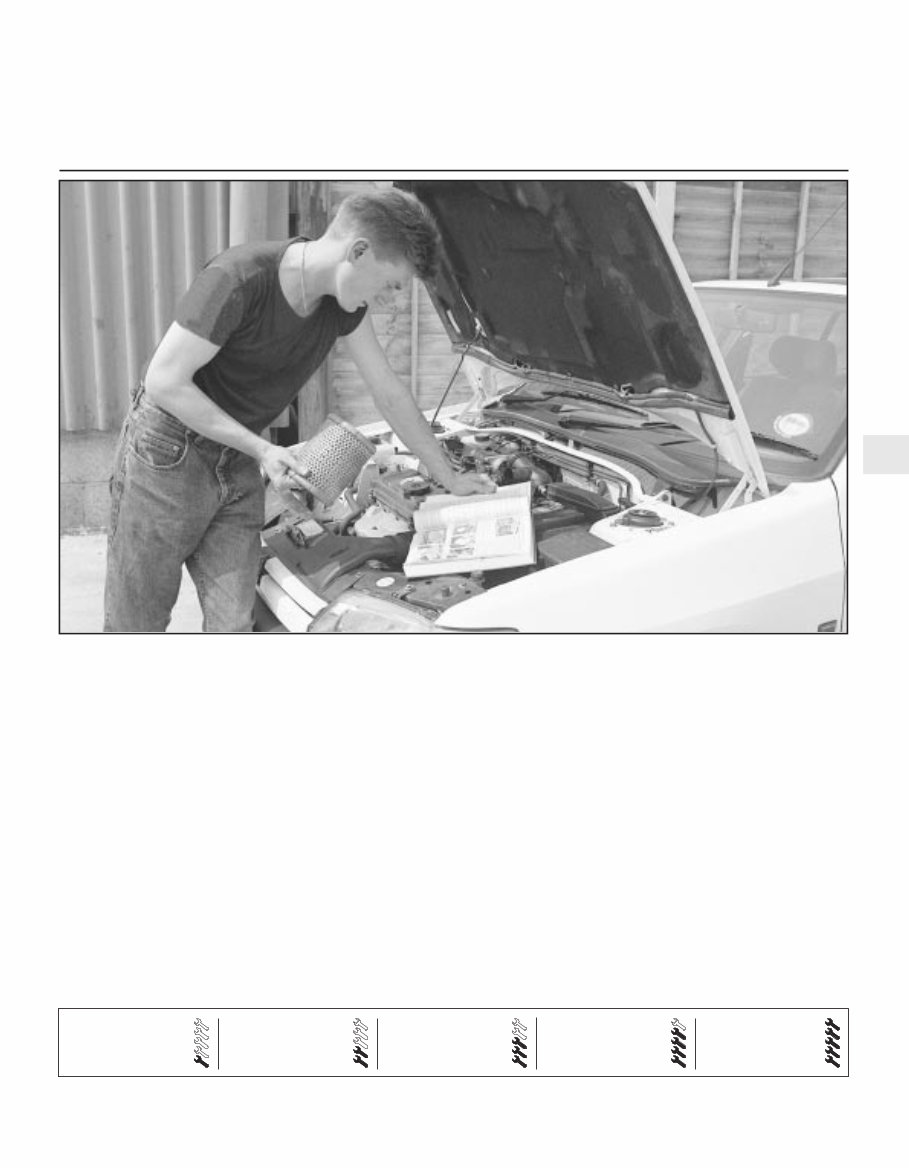
1 Fuse and relay box
2 Windscreen wiper motor
3 Engine oil dipstick
4 Carburettor
5 Fuel pump
6 Battery negative terminal
7 Brake master cylinder reservoir
8 Distributor
9 Ignition coil
10 Washer reservoir
11 Thermostat housing
12 Oil filler cap
13 Vehicle identification plate
14 Engine tuning decal
15 Cooling system expansion tank
16 Suspension strut top mounting
Engine and under bonnet component location on 1986 1.4 litre models (air cleaner removed for clarity)
1 Fuse and relay box
2 Windscreen wiper motor
3 Crankcase emission control filter
4 Engine oil dipstick
5 Throttle housing
6 Inlet manifold
7 Throttle position sensor
8 Charge air temperature sensor
9 Distributor
10 Brake master cylinder reservoir
11 Battery negative terminal
12 Ignition coil
13 Fuel filter
14 Washer reservoir
15 Air cleaner
16 Fuel distributor
17 Inlet air hose
18 Turbocharger
19 Vehicle identification plate
20 Engine tuning decal
21 Cooling system expansion tank
22 Suspension strut top mounting
Engine and under bonnet component locations on 1986 RS Turbo models
1•6 Maintenance - Component location
1 Ventilation air inlet duct
2 Battery
3 Bonnet hinge
4 Suspension strut upper mounting
5 Brake system fluid reservoir
6 Ignition system ESC module
7 Windscreen washer reservoir filler cap
8 Transmission housing
9 Clutch release lever
10 Cooling fan motor
11 Starter motor
12 Engine oil filler neck (cap removed)
13 Exhaust manifold shield
14 Alternator
15 Coolant thermostat and fan thermal
switch
16 Coolant expansion tank
17 Spark plug HT leads
18 Engine oil dipstick
19 Throttle cable
20 Choke cable
21 Carburettor
22 Fusebox
23 Windscreen wiper motor
Engine and underbonnet components location on 1989 1.3 litre HCS model (air cleaner removed for clarity)
1 Anti-roll bar clamp
2 Anti-roll bar
3 Front suspension lower arm
4 Steering tie-rod
5 Transmission support crossmember
6 Gearchange rod
7 Gearchange stabiliser
8 Driveshaft
9 Engine oil drain plug
10 Brake caliper
11 Alternator
12 Exhaust front pipe
13 Starter motor
Front underbody view of a 1986 1.4 litre Saloon model
Maintenance procedures 1•7
1
General information
This Chapter is designed to help the home
mechanic maintain his/her vehicle for safety,
economy, long life and peak performance.
The Chapter contains a master
maintenance schedule, followed by Sections
dealing specifically with each task on the
schedule. Visual checks, adjustments,
component renewal and other helpful items
are included. Refer to the accompanying
illustrations of the engine compartment and
the underside of the vehicle for the locations
of the various components.
Servicing of your vehicle in accordance with
the mileage/time maintenance schedule and
the following Sections will provide a planned
maintenance program, which should result in
a long and reliable service life. This is a
comprehensive plan, so maintaining some
items but not others at the specified service
intervals will not produce the same results.
As you service your vehicle, you will
discover that many of the procedures can -
and should - be grouped together because of
the particular procedure being performed, or
because of the close proximity of two
otherwise unrelated components to one
another. For example, if the vehicle is raised
for any reason, the exhaust can be inspected
at the same time as the suspension and
steering components.
The first step in this maintenance program
is to prepare yourself before the actual work
begins. Read through all the Sections relevant
to the work to be carried out, then make a list
and gather together all the parts and tools
required. If a problem is encountered, seek
advice from a parts specialist, or a dealer
service department.
If, from the time the vehicle is new, the
routine maintenance schedule is followed
closely and frequent checks are made of fluid
levels and high wear items, as suggested
throughout this manual, the engine will be
kept in relatively good running condition and
the need for additional work will be minimised.
It is possible that there will be times when
the engine is running poorly due to the lack of
regular maintenance. This is even more likely
if a used vehicle, which has not received
regular and frequent maintenance checks, is
purchased. In such cases, additional work
may need to be carried out, outside of the
regular maintenance intervals.
If engine wear is suspected, a compression
test will provide valuable information
regarding the overall performance of the main
internal components. Such a test can be used
as a basis to decide on the extent of the work
to be carried out. If for example a
compression test indicates serious internal
engine wear, conventional maintenance as
described in this Chapter will not greatly
improve the performance of the engine, and
may prove a waste of time and money, unless
extensive overhaul work is carried out first.
The following series of operations are those
most often required to improve the
performance of a generally poor-running
engine.
a) Clean, inspect and test the battery
(Section 5).
b) Check the levels of all the engine related
fluids (Section 3).
c) Check the condition and tension of the
alternator drivebelt (Section 20).
d) Check the condition of the spark plugs
and renew if necessary (Section 15).
e) Check the condition of the air cleaner
element, and renew if necessary (Sec-
tion 34).
f) Check the condition of all hoses and
check for fluid leaks.
g) Check and if necessary adjust the idle
speed (where possible) (Section 10).
2 Intensive maintenance
1 Introduction
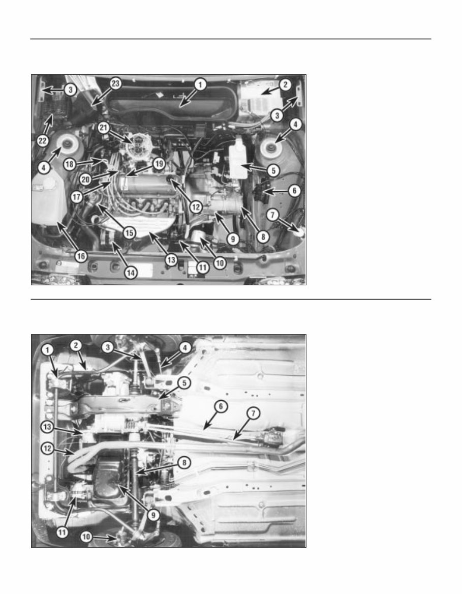
1 Fuel filler pipe
2 Suspension lower arm
3 Tie-bar
4 Tie-bar front mounting
5 Fuel tank
6 Handbrake cable adjuster
7 Exhaust mounting
8 Exhaust intermediate silencer
9 Exhaust rear silencer
10 Rear towing eye
Rear underbody view of a 1986 1.4 litre Saloon model
1 Frequent oil and filter changes are the most
important preventative maintenance
procedures that can be undertaken by the DIY
owner. As engine oil ages, it becomes diluted
and contaminated, which leads to premature
engine wear.
2 Before starting this procedure, gather
together all the necessary tools and materials.
Also make sure that you have plenty of clean
rags and newspapers handy to mop up any
spills. Ideally, the engine oil should be warm,
as it will drain better and more built-up sludge
will be removed with it. Take care, however,
not to touch the exhaust or any other hot
parts of the engine when working under the
vehicle. To avoid any possibility of scalding,
and to protect yourself from possible skin
irritants and other harmful contaminants in
used engine oils, it is advisable to wear rubber
gloves when carrying out this work. Access to
the underside of the vehicle will be greatly
improved if it can be raised on a lift, driven
onto ramps or jacked up and supported on
axle stands (see “Jacking and Vehicle
Support”). Whichever method is chosen,
make sure that the vehicle remains as level as
possible, to enable the oil to drain fully.
3 Remove the oil filler cap from the rocker cover,
then position a container beneath the sump.
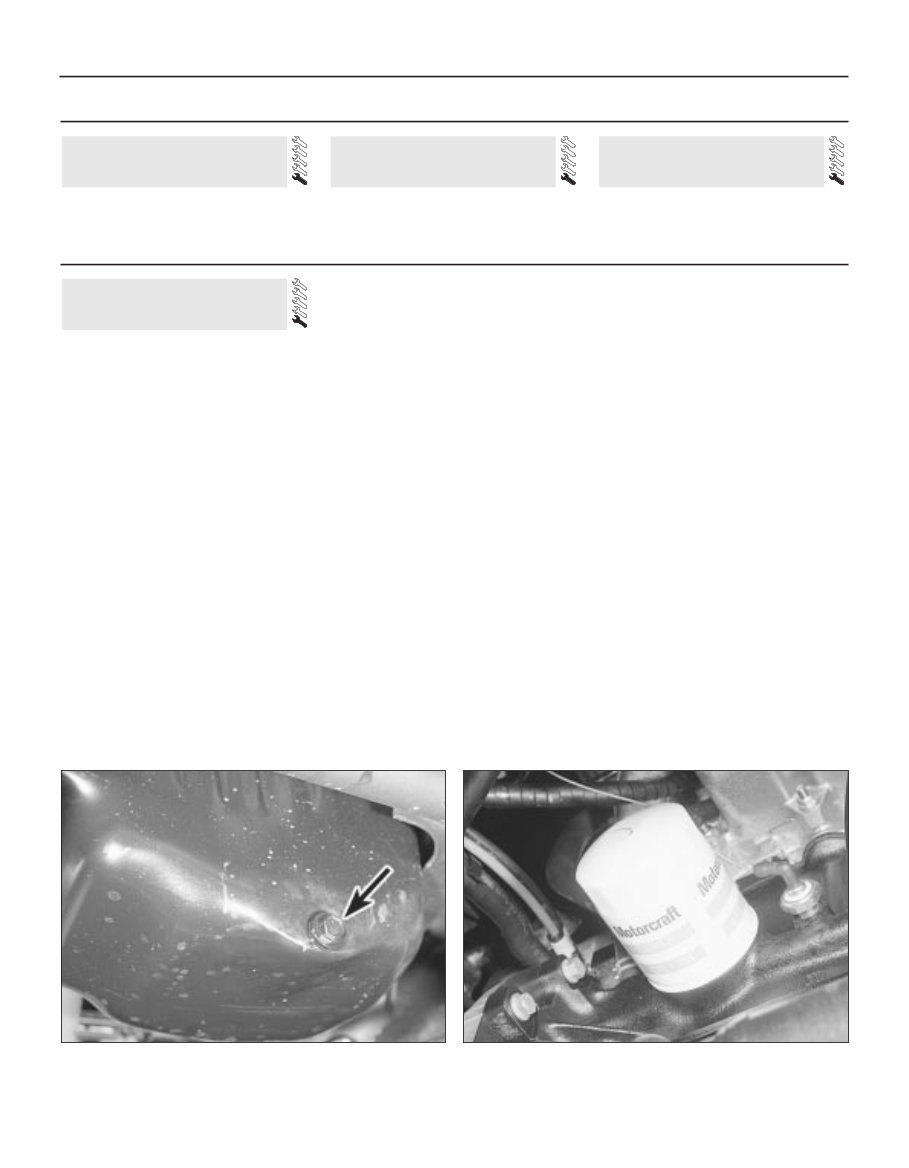
4 Clean the drain plug and the area around it,
then slacken it using a suitable socket or
spanner (see illustration). If possible, try to
keep the plug pressed into the sump while
unscrewing it by hand the last couple of turns.
As the plug releases from the threads, move it
away sharply so the stream of oil issuing from
the sump runs into the container, not up your
sleeve!
5 Allow some time for the old oil to drain,
noting that it may be necessary to reposition
the container as the oil flow slows to a trickle.
6 After all the oil has drained, wipe off the
drain plug with a clean rag and check the
condition of the sealing washer. Renew the
washer if necessary. Clean the area around
the drain plug opening, then refit and tighten
the plug to the specified torque setting.
7 Move the container into position under the
oil filter. The oil filter is located at the rear of
the cylinder block, and is accessible from
under the vehicle (see illustration)
8 Using an oil filter removal tool, slacken the
filter initially. Loosely wrap some rags around
the oil filter, then unscrew it and immediately
position it with its open end uppermost to
prevent further spillage of oil. Remove the oil
filter from the engine compartment and empty
the oil into the container.
9 Use a clean rag to remove all oil, dirt and
sludge from the filter sealing area on the
engine. Check the old filter to make sure that
the rubber sealing ring hasn’t stuck to the
engine. If it has, carefully remove it.
10 Apply a light coating of clean oil to the
sealing ring on the new filter, then screw it into
position on the engine. Tighten the filter firmly
by hand only - do not use any tools. Wipe
clean the exterior of the oil filter.
11 Remove the old oil and all tools from
under the vehicle, then (if applicable) lower the
vehicle to the ground.
12 Fill the engine with the specified quantity
and grade of oil, as described in “Weekly
checks”. Pour the oil in slowly, otherwise it
may overflow from the top of the rocker cover.
Check that the oil level is up to the correct
level on the dipstick, then refit and tighten the
oil filler cap.
13 Run the engine for a few minutes, and
check that there are no leaks around the oil
filter seal and the sump drain plug.
14 Switch off the engine and wait a few
minutes for the oil to settle in the sump once
more. With the new oil circulated and the filter
now completely full, recheck the level on the
dipstick and add more oil if necessary.
15 Dispose of the used engine oil safely with
reference to “General repair procedures” in
the Reference Sections at the end of this
manual.
6 Engine oil and filter renewal
Every 6000 miles or 6 months
1•8 Maintenance procedures
See “Weekly checks” starting on Page 0•10. See “Weekly checks” starting on Page 0•10. See “Weekly checks” starting on Page 0•10.
5 Battery check 4 Tyre checks 3 Fluid level checks
Weekly checks
6.7 Oil filter location - CVH engine 6.4 Engine oil drain plug (arrowed) -
CVH engine
Every 6000 miles or 6 Months 1•9
1
1 Simply pull the oil filler cap from the rocker
cover and, where applicable, disconnect the
hose(s) from the cap.
2 Inspect the filler cap, and if necessary clean
the cap using clean petrol to remove any
deposits.
3 Ensure that the cap is completely dry
before refitting.
1 Visually inspect the engine joint faces,
gaskets and seals for any signs of water or oil
leaks. Pay particular attention to the areas
around the rocker cover, cylinder head, oil
filter and sump joint faces. Bear in mind that
over a period of time some very slight
seepage from these areas is to be expected
but what you are really looking for is any
indication of a serious leak. Should a leak be
found, renew the offending gasket or oil seal
by referring to the appropriate Chapter(s) in
this manual.
2 Similarly, check the transmission for oil
leaks, and investigate and rectify and
problems found.
3 Check the security and condition of all the
engine related pipes and hoses. Ensure that
all cable-ties or securing clips are in place and
in good condition. Clips which are broken or
missing can lead to chafing of the hoses,
pipes or wiring which could cause more
serious problems in the future.
4 Carefully check the condition of all coolant,
fuel and brake hoses. Renew any hose which
is cracked, swollen or deteriorated. Cracks
will show up better if the hose is squeezed.
Pay close attention to the hose clips that
secure the hoses to the system components.
Hose clips can pinch and puncture hoses,
resulting in leaks. If wire type hose clips are
used, it may be a good idea to replace them
with screw-type clips.
5 With the vehicle raised, inspect the fuel
tank and filler neck for punctures, cracks and
other damage. The connection between the
filler neck and tank is especially critical.
Sometimes a rubber filler neck or connecting
hose will leak due to loose retaining clamps or
deteriorated rubber.
6 Similarly, inspect all brake hoses and metal
pipes. If any damage or deterioration is
discovered, do not drive the vehicle until the
necessary repair work has been carried out.
Renew any damaged sections of hose or pipe.
7 Carefully check all rubber hoses and metal
fuel lines leading away from the petrol tank.
Check for loose connections, deteriorated
hoses, crimped lines and other damage. Pay
particular attention to the vent pipes and
hoses which often loop up around the filler
neck and can become blocked or crimped.
Follow the lines to the front of the vehicle
carefully inspecting them all the way. Renew
damaged sections as necessary.
8 From within the engine compartment,
check the security of all fuel hose attachments
and pipe unions, and inspect the fuel hoses
and vacuum hoses for kinks, chafing and
deterioration.
9 Where applicable, check the condition of
the oil cooler hoses and pipes.
10 Check the condition of all exposed wiring
harnesses.
11 Also check the engine and transmission
components for signs of fluid leaks.
Check the tightness of the exhaust
manifold securing nuts using a torque wrench.
Note: Before carrying out any carburettor
adjustment, ensure that the contact breaker
points, ignition timing and spark plug gaps (as
applicable) are set as specified and that the
distributor is operating correctly (where
applicable). To carry out the adjustments an
accurate tachometer will be required and the
use of an exhaust gas analyser (CO meter) is
also preferable.
Models with Ford VV carburettor
Idle speed
1 With the engine at normal operating
temperature, connect a tachometer in
accordance with the manufacturer’s
instructions.
2 Disconnect the wiring multi-plug from the
radiator cooling fan thermostatic switch in the
thermostat housing and bridge the two
contacts in the plug using a suitable length of
wire. This is necessary so that the cooling fan
runs continuously during adjustment.
3 On automatic transmission models slacken
the adjuster screw on the throttle valve shaft
lever to give clearance of 2 to 3 mm (0.079 to
0.118 in) - see Chapter 7, Part B.
4 Ensure that the air cleaner is fitted and that
its vacuum hoses are not in any way trapped
or pinched, particularly between the air cleaner
body and the top face of the carburettor.
5 Run the engine at 3000 rpm for 30 seconds,
then allow it to idle and note the idle speed. If
using an exhaust gas analyser it should be
noted that initially the CO% reading will rise,
but then fall and stabilise after a period of 5 to
25 seconds. The CO reading should then be
as specified.
Idle mixture
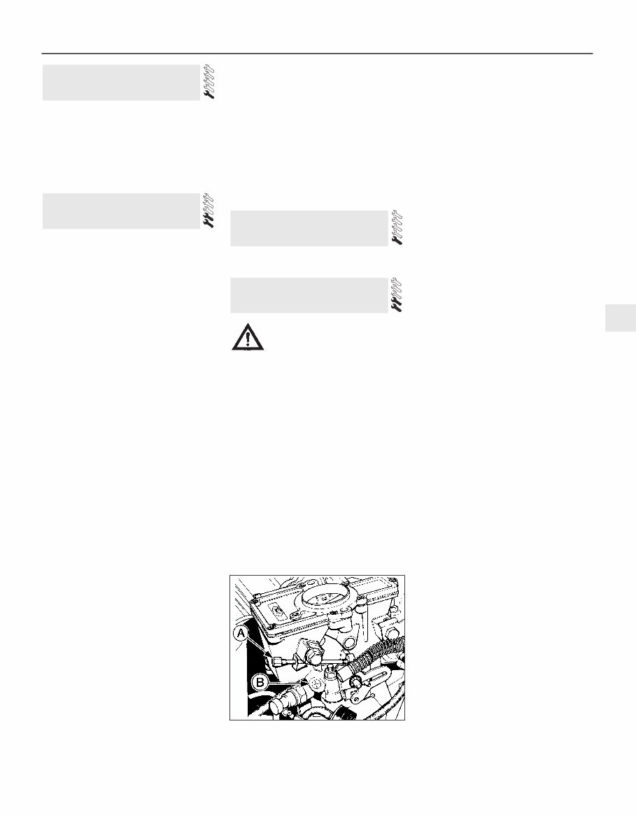
6 If necessary, adjust the idle speed
adjustment screw to give the specified idle
speed (see illustration).
7 Adjustment of the CO content (mixture) is
not normally required during routine
maintenance, but if the reading noted in
paragraph 5 is not as given in the
Specifications first remove the tamperproof
plug, prising it free using a small screwdriver.
8 Run the engine at 3000 rpm for 30 seconds,
then allow it to idle. Adjust the mixture screw
(see illustration 10.6) within 30 seconds. If
more time is required run the engine at 3000
rpm again for 30 seconds.
9 Adjust the idle speed if necessary and
recheck the CO content.
10 Fit a new tamperproof plug to the mixture
adjuster screw on completion. It should be
noted that mixture adjustment without a CO
analyser is not accurate and therefore not
recommended.
11 On completion disconnect the
instruments, remove the cooling fan bridging
wire and reconnect the multi-plug.
12 On automatic transmission models adjust
the downshift linkage (Chapter 7, Part B).
Models with Weber 2V carburettor
13 The procedure is the same as for the Ford
VV carburettor as described previously in this
Section, but the adjusting screw locations are
as shown (see illustrations).
Models with Bosch K-Jetronic
fuel injection system
14 The idle speed and fuel mixture
adjustments will normally only be required
after the installation of new components.
10 Idle speed and mixture
adjustment
9 Exhaust manifold nut check -
RS Turbo models
8 Fluid leak check
7 Oil filler cap cleaning - OHV
and HCS engines
10.6 Idle speed adjustment screw (A) and
mixture adjustment screw (B) - Ford VV
carburettor
Caution: Certain adjustment
points in the fuel system are
protected by “tamperproof”
caps, plugs or seals. In some
EEC countries (though not yet in the UK)
it is an offence to drive a vehicle with
broken or missing tamperproof seals.
Before disturbing a tamperproof seal,
satisfy yourself that you will not be
breaking any local or national laws by
doing so, and fit a new seal after
adjustment is complete where required by
law. Do not break tamperproof seals on a
vehicle which is still under warranty.
You're Reading a Preview
What's Included?
Fast Download Speeds
Online & Offline Access
Access PDF Contents & Bookmarks
Full Search Facility
Print one or all pages of your manual
$31.99
Viewed 18 Times Today


Secure transaction
What's Included?
Fast Download Speeds
Online & Offline Access
Access PDF Contents & Bookmarks
Full Search Facility
Print one or all pages of your manual
$31.99
The Ford Escort 1980-1990 Best Service Repair Manual is an invaluable resource for Ford Escort owners and enthusiasts. This comprehensive manual covers a wide range of models from 1980 to 1990, providing detailed instructions and diagrams to help you maintain, repair, and restore your vehicle.
Features of the Ford Escort 1980-1990 Best Service Repair Manual include:
- Step-by-step instructions for all repairs, from simple maintenance tasks to complex engine overhauls
- Detailed diagrams and illustrations to guide you through each procedure
- Troubleshooting guides to help diagnose and solve common problems
- Tips and techniques from professional mechanics to ensure successful repairs
- Information on routine maintenance procedures, including oil changes, tire rotations, and brake inspections
Whether you're a seasoned mechanic or a do-it-yourself enthusiast, the Ford Escort 1980-1990 Best Service Repair Manual is an essential tool for keeping your Ford Escort running smoothly. With its thorough coverage of all models from 1980 to 1990, this manual will help you save time and money by enabling you to tackle repairs and maintenance tasks with confidence.


