


Workshop Manual
WARNING: Before beginning any service procedure in this manual, refer to health and safety warnings in section
100-00 General Information. Failure to follow this instruction may result in serious personal injury.
Refer to: Health and Safety Precautions

100-00 General Information 2015 Escape
Description and Operation Procedure revision date: 03/10/2021
About this Manual
Introduction
WARNING: Before beginning any service procedure in this manual, refer to health and safety warnings in section
100-00 General Information. Failure to follow this instruction may result in serious personal injury.
For additional information, refer to: Health and Safety Precautions (100-00 General Information, Description and
Operation).
This manual describes and directs repair procedures specified by Ford Motor Company for the vehicle. Critical health and
safety precautions are included. Anyone who deviates from these instructions risks compromising personal safety or vehicle
integrity.
SECTION CONTENT
This manual is divided into groups, each containing sections numbered based on the component part number. Section
contents may include:
Specifications
Fluid capacities, component specifications and torque values not covered in other procedures
Description and Operation
Overview of the system, component locations, and system operation
Diagnosis and Testing
Symptom charts, DTC charts and diagnostic tests
See the Diagnosis and Testing Information in this document
General Procedures
Service adjustments, electronic programming and other special procedures
Removal and Installation
Component removal and installation instructions
Removal
Component removal instructions
Installation
Component installation instructions
Disassembly and Assembly
Component disassembly and assembly instructions
Disassembly and Assembly of Subassemblies
Assembly disassembly and assembly instructions
IMPORTANT INFORMATION
Section number 100-00 General Information contains the following important information (including this document):
Critical Health and Safety Precautions - service safety precautions applicable to the entire manual.
For additional information, refer to: Health and Safety Precautions (100-00 General Information, Description and
Operation).
A Symbols Glossary - definitions of the action directed by each symbol.
For additional information, refer to: Symbols Glossary (100-00 General Information, Description and Operation).
Diagnostic Methods - support information for diagnostics.
For additional information, refer to: Diagnostic Methods (100-00 General Information, Description and Operation).
Warnings, Notices and Notes
WARNINGS
Warnings provide information to avoid personal injury and to make sure service actions on critical safety systems are
performed correctly. Warnings that apply to an entire system or workshop manual section are located in section 100-00
Description and Operation, Health and Safety Precautions.
For additional information, refer to: Health and Safety Precautions (100-00 General Information, Description and
Operation).
NOTICES (in some publications, CAUTIONS)
Notices provide information to avoid damage to the vehicle or a component.
NOTES
Notes provide information critical for a complete and effective repair.
Warnings, Notices, or Notes that apply to an entire procedure will be placed at the beginning of the procedure. Warnings,
Notices, or Notes that apply to a single step are placed at the beginning of the step. Those that apply to a group of steps will
be placed at the first step requiring it.
Safety Relevant Systems
Repair of a vehicle safety relevant system is to be achieved only by replacement of the failed component(s), unless specified
otherwise in the procedure. Repair of a vehicle safety relevant system component should not be attempted.
If directed during assembly of system components, lubricate any seal(s) only with the specified material. Failure to follow
this instruction may result in seal failure and leakage.
Specified Chemicals or Materials
Throughout this manual, chemicals or materials are specified that must be used to properly complete a service procedure or
diagnostic step. In the event a specific material is not readily available, a substitute material meeting the same specification
may be used. Ford has not reviewed third party products for compliance with environmental, health or safety regulations and
is not responsible for their use. Use of third party products is at your own risk. Additionally, such products may cause
degraded performance, premature failures, and/or vehicle component damage. All chemicals or materials used for vehicle
servicing should be checked for compliance with local environmental and health and safety regulations.
LH and RH Designations
All LH and RH designations are oriented from the driver's seat position looking forward.
Vehicle LH and RH definition
Item Part Number Description
1 — LH (left-hand)
2 — RH (right-hand)
All LH and RH engine designations are oriented from the flywheel position looking toward the crankshaft pulley.
Powertrain LH and RH definition
Item Part Number Description
1 — Front
2 — RH (right-hand)
3 — Rear
4 — LH (left-hand)
Standard Practices
The following rules apply, unless specified differently in the procedure:
FASTENERS
Reuse standard fasteners.
Replace fasteners with self-locking features.
Examples of fastener self-locking coatings or mechanical locking (with the locking features highlighted yellow)
are shown in the illustration.
Examples of self-locking nuts and bolts
Item Part Number Description
1 — Completely coated self-locking bolt
2 — Partially coated self-locking bolt
3 — Self-locking bolt with a locking washer
4 — Self-locking nut with a plastic locking insert
5 — Self-locking nut with thread deformation (3 indentations)
6 — Self-locking nut with thread deformation (to oval shape)
7 — Self-locking nut with integrated locking ring
THREAD FORMING FASTENERS
The following is a general description of best practices to be followed during handling of thread forming fasteners and
mating components.
Manual Torque Application
Hand tools are required for installation of a thread forming fastener. Do NOT use power tools, as the possibility for over-
torqueing or stripped threads exists. If a fastener is over-torqued, the joint can fail.
Hand Start Fasteners in Reverse
To avoid the possibility of cross-threading pre-existing threads during fastener replacement, begin by first hand-inserting the
new fastener and rotating counter-clockwise. This reverse rotation allows for the location of existing fastener threads to
ensure the fastener does not cross-thread upon thread re-engagement. Once the existing fastener threads are located, hand-
start individual fasteners manually until finger tight.
Risks of Over-Torque
Consult the Workshop Manual procedure when torqueing thread forming fasteners and follow torque specification as listed.
Make sure the fastener is fully seated against the mating component with no gap during reassembly.
Corrosion
During fastener replacement, inspect both fastener and mating component for signs of rust or other corrosion. If corrosion is
found, replace corroded components with new components.
Stripped Threads
If internal (mating component) threads or external (fastener) threads appear stripped or galled, replace both fastener and
mating component. When tightening, if minimum torque is not reached, internal threads on mating component may have
stripped. Remove the fastener to inspect and replace mating component if stripped threads are found.
Face Seals
When replacing fasteners, inspect mating component surface for debris, damage, disturbance, wear, or abrasion and replace
any seals or gaskets if damage is found.
SEALS AND GASKETS
Replace seals and gaskets, unless specified differently in the procedure.
EXTERIOR TRIM PARTS
Replace exterior trim parts fastened with glue or adhesive tape, unless specified differently in the procedure.
Mechanical Procedures
Illustrations in this manual may be used instead of written step instructions. Color-coding (see color scheme illustration) is
used to communicate the required step action or actions. Service action icons may be used to add information regarding the
required action.
For additional information, refer to: Symbols Glossary (100-00 General Information, Description and Operation).
Illustration Color-coding
Item
Part
Number Description
1 — Blue - Target or primary component to be removed/installed (or
disassembled/assembled).
2 — Green - Components that need to be removed prior to or installed
after the target/primary.
3 — Brown - Components that need to be removed prior to or installed
after the target/primary.
4 — Yellow - Components to be set aside for access, but not removed.
Also highlighted areas to inspect or adjust.
5 — Magenta - Electrical connectors and fasteners such as nuts, bolts,
clamps, or clips to be: detached, attached, loosened, moved,
removed or installed.
6 — Pale Blue - Special tool(s), general equipment, or common tools
used in an uncommon way.
Other color coding
Alternating Blue and White
Chemical, adhesive or sealer apply areas
Red
Sectioned or cut-away areas
Grey
Background components shown for location information
ILLUSTRATION TASK SEQUENCE

Components that must be removed or installed in a specific sequence are identified with a numbered callout. Any associated
step text is numbered accordingly.
Simple procedure example showing color-coding and task sequence.
Black arrows are used to draw attention to components (usually fasteners). Arrows with multiples specified (here, x2)
identify an identical number of fasteners or items. Callouts (numbers inside circles) show a required sequence or tightening
torque.
In the illustration, the callouts indicate the removal sequence, which is reversed for installation. The yellow coloring of the
hose indicates it is to be positioned aside (not removed). Two identical (magenta-colored) fasteners are indicated by the x2
arrow. The fasteners in this illustration require different torques (same torque for the x2 fasteners) so numbered callouts are
used to identify them with torque values in the associated step text. The (magenta-colored) hose clamp is another fastener to
be removed.
Examples of fastener removal sequence and an identical service action for 12 fasteners. Other possible symbols are
shown on the right.
Example of fastener sequence information with two persons required for the service action
HIDDEN DETAILS
Separate detail boxes or transparent components may be used to show hidden items in an illustration.
Example of hidden fastener information
SERVICE ACTION ICONS
Service action icons may be used to add information regarding the required action.
For additional information, refer to: Symbols Glossary (100-00 General Information, Description and Operation).
Location symbols show the location of a component or system on the vehicle.
Example of service action icons pointing to highlighted components.
Movement arrows and service action icons show three dimensional or rotational movements.
Instruction symbols are used to apply sealer, lubricant, weight, tape or cleaning detergent to a component.
Measurement symbols provide the information required to perform a specific measurement. These symbols may
include specific values.
SPECIAL TOOLS, POWER TOOLS, GENERAL EQUIPMENT, MATERIALS AND TORQUE VALUES

Commercially available power tools, hand tools and general equipment are used in service along with Ford special tools.
Use of power tools is acceptable during removal or disassembly procedures unless specified otherwise in the service
procedure. Power tools are not to be used during assembly or installation, with the exception of wheel installation. It is
permissible to use a pneumatic impact wrench in conjunction with a torque stick. Follow the torque stick manufacturer's
recommendations for use when applying the tightening torque to the wheel nuts.
When Ford special tools are required for the procedure, the tool and tool number are shown in an illustration. Special tool
numbers, general equipment, materials or torque values for the procedure step are shown in the text steps.
Example of special service tool and symbol used to hold the gear shift in the required gear position. Other possible
symbols are shown on the right.
Example of two illustrations used together with sequence steps, service action icons and special service tools
Tool symbols direct the use of standard tools. The tool size or dimension may be specified.
HEALTH AND SAFETY SYMBOLS
Some procedures may contain health and safety symbols that are associated with a specific service action.
For additional information, refer to: Symbols Glossary (100-00 General Information, Description and Operation).
Always read and understand all health and safety precautions found in Section 100-00 before beginning any procedure. For
additional information, refer to: Health and Safety Precautions (100-00 General Information, Description and Operation).
ISO warning symbols may be used to indicate potential hazards.
These symbols prohibit various hazardous actions
These symbols direct the use of personal protection equipment
Diagnosis and Testing Information
ELEMENTS OF DIAGNOSIS AND TESTING
Diagnosis and Testing may include:
Preliminary Inspection
In older manuals, Inspection and Verification
Symptom Chart
DTC Chart
Pinpoint Tests
Component Tests
Some diagnostics may be contained in Symptom Based Diagnostics. Some engine performance and emission diagnostics
may be placed in a separately published PC/ED manual.
MODULE NAMES MATCH THE DIAGNOSTIC SCAN TOOL
Module names and PID names in this manual match the Ford diagnostic scan tool: IDS or FDRS .

The same diagnostic scan tool module name is found in some DTC definitions (for example, U024B Lost Communication
with Seat Control Module "G").
MODULE DESCRIPTIVE NAMES
A descriptive name is sometimes added to the diagnostic scan tool name to clarify module function. The descriptive name
will be followed by the diagnostic scan tool acronym in brackets.
Example: “Driver Active Motion Seat Module [SCMG]”.
Driver Active Motion Seat Module is the descriptive name added to clarify the function of the SCMG.
The SCMG acronym is used by diagnostic scan tool, defined as “Seat Control Module G”.
100-00 General Information 2015 Escape
Description and Operation Procedure revision date: 07/27/2023
Symbols Glossary
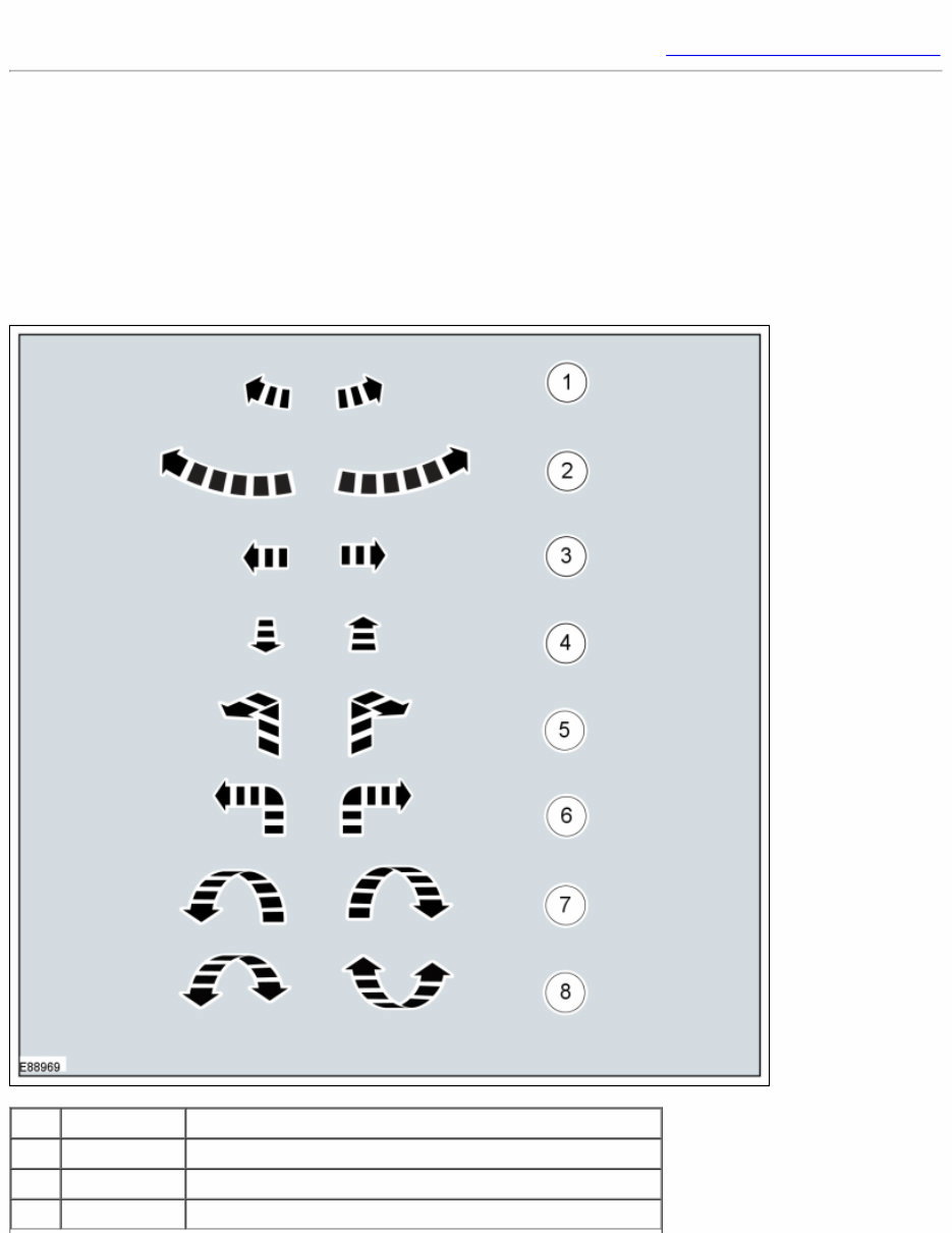
Symbols are used inside the graphics and in the text area to enhance the information display.
Movement Symbols
Movement symbols provide detailed information to a required component movement. These component movements can be
rotational or 1-3 dimensional movements.
Item Part Number Description
1 — Minor component movement clockwise/counterclockwise
2 — Major component movement clockwise/counterclockwise
3 — Component movement to the left/right/up/down
4 — Component movement towards/away
5 — 3 dimensional component movement
6 — 2 dimensional component movement
7 — 3 dimensional component rotation
8 — 3 dimensional component cycling
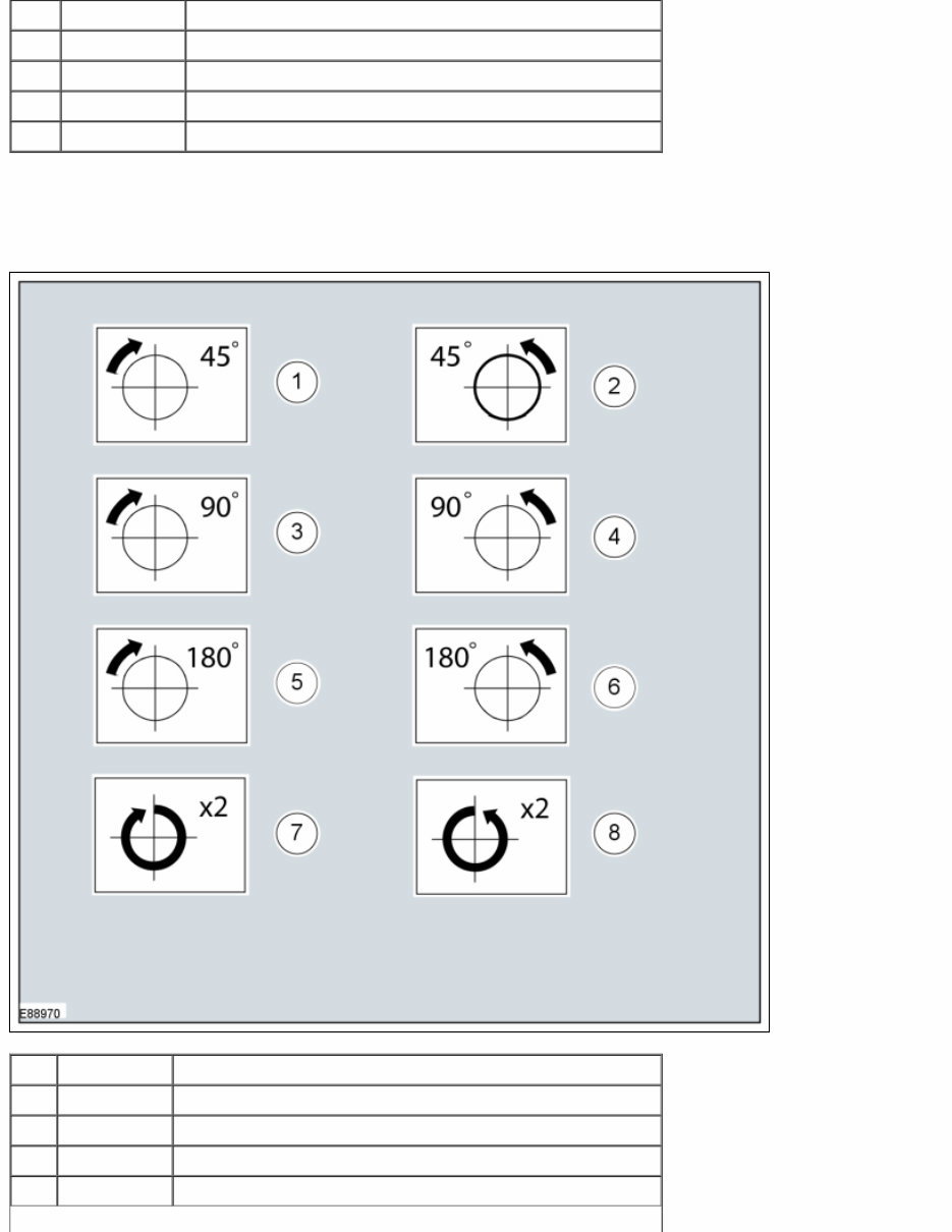
Turn Symbols
Turn symbols are used to provide further information on the direction or angle of component turns.
Item Part Number Description
1 — Turn the component clockwise through 45°
2 — Turn the component counterclockwise through 45°
3 — Turn the component clockwise through 90°
4 — Turn the component counterclockwise through 90°
You're Reading a Preview
What's Included?
 Lifetime Access
Fast Download Speeds
Online & Offline Access
Access PDF Contents & Bookmarks
Full Search Facility
Print one or all pages of your manual
$37.99
2015 Ford Escape - M2 (C520 NA) Service & Repair Manual
Viewed 74 Times Today

What's Included?
Lifetime Access
Fast Download Speeds
Online & Offline Access
Access PDF Contents & Bookmarks
Full Search Facility
Print one or all pages of your manual
$37.99

Secure transaction
What's Included?
Lifetime Access
Fast Download Speeds
Online & Offline Access
Access PDF Contents & Bookmarks
Full Search Facility
Print one or all pages of your manual
Description
The 2015 Ford Escape Service & Repair Manual provides a comprehensive guide for maintaining, troubleshooting, and repairing this vehicle.
- This manual is suitable for both professional mechanics and DIY enthusiasts, offering detailed instructions on a wide range of topics.
- With its in-depth coverage, you'll gain a thorough understanding of the vehicle's systems, components, and procedures.
- Designed to be a valuable resource for those who need to work on their Ford Escape, this manual is packed with technical information, diagrams, and step-by-step guides.
- It covers various aspects of vehicle maintenance and repair, including troubleshooting, Diagnosis, and repair procedures for electrical, mechanical, and body systems.
- This manual is an essential tool for anyone who wants to ensure their vehicle is properly maintained, fixed, and upgraded to optimal condition.
Get the knowledge you need to keep your Ford Escape running smoothly and efficiently with this comprehensive service and repair manual.


