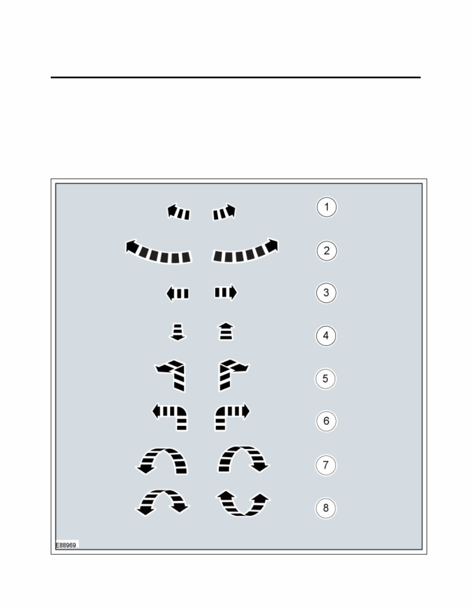
Symbols Glossary Symbols are used inside the graphics and in the text area to enhance the information display. Movement Symbols Movement symbols provide detailed information to a required component movement. These component movements can be rotational or 1-3 dimensional movements. 100-00 General Information 2013 - 2014 Escape Description and Operation Procedure revision date: 04/3/2013 Page 1 of 33 2014-04-30 file://C:\TSO\tsocache\VDTOM_1168\SDZ~us~en~file=SDZG1615041.HTM~gen~ref....
Turn Symbols Turn symbols are used to provide further information on the direction or angle of component turns. Item Part Number Description 1 — Minor component movement clockwise/counterclockwise 2 — Major component movement clockwise/counterclockwise 3 — Component movement to the left/right/up/down 4 — Component movement towards/away 5 — 3 dimensional component movement 6 — 2 dimensional component movement 7 — 3 dimensional component rotation 8 — 3 dimensional component cycling Page 2 of 33 2014-04-30 file://C:\TSO\tsocache\VDTOM_1168\SDZ~us~en~file=SDZG1615041.HTM~gen~ref.... tomsn048@gmail.com
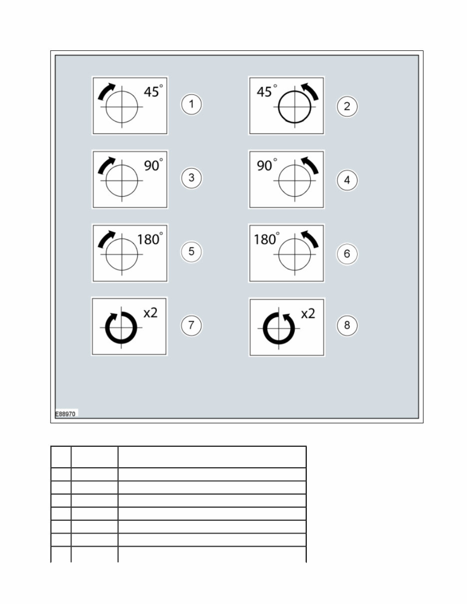
Item Part Number Description 1 — Turn the component clockwise through 45° 2 — Turn the component counterclockwise through 45° 3 — Turn the component clockwise through 90° 4 — Turn the component counterclockwise through 90° 5 — Turn the component clockwise through 180° 6 — Turn the component counterclockwise through 180° 7 — Turn the component clockwise through 2 complete Page 3 of 33 2014-04-30 file://C:\TSO\tsocache\VDTOM_1168\SDZ~us~en~file=SDZG1615041.HTM~gen~ref....
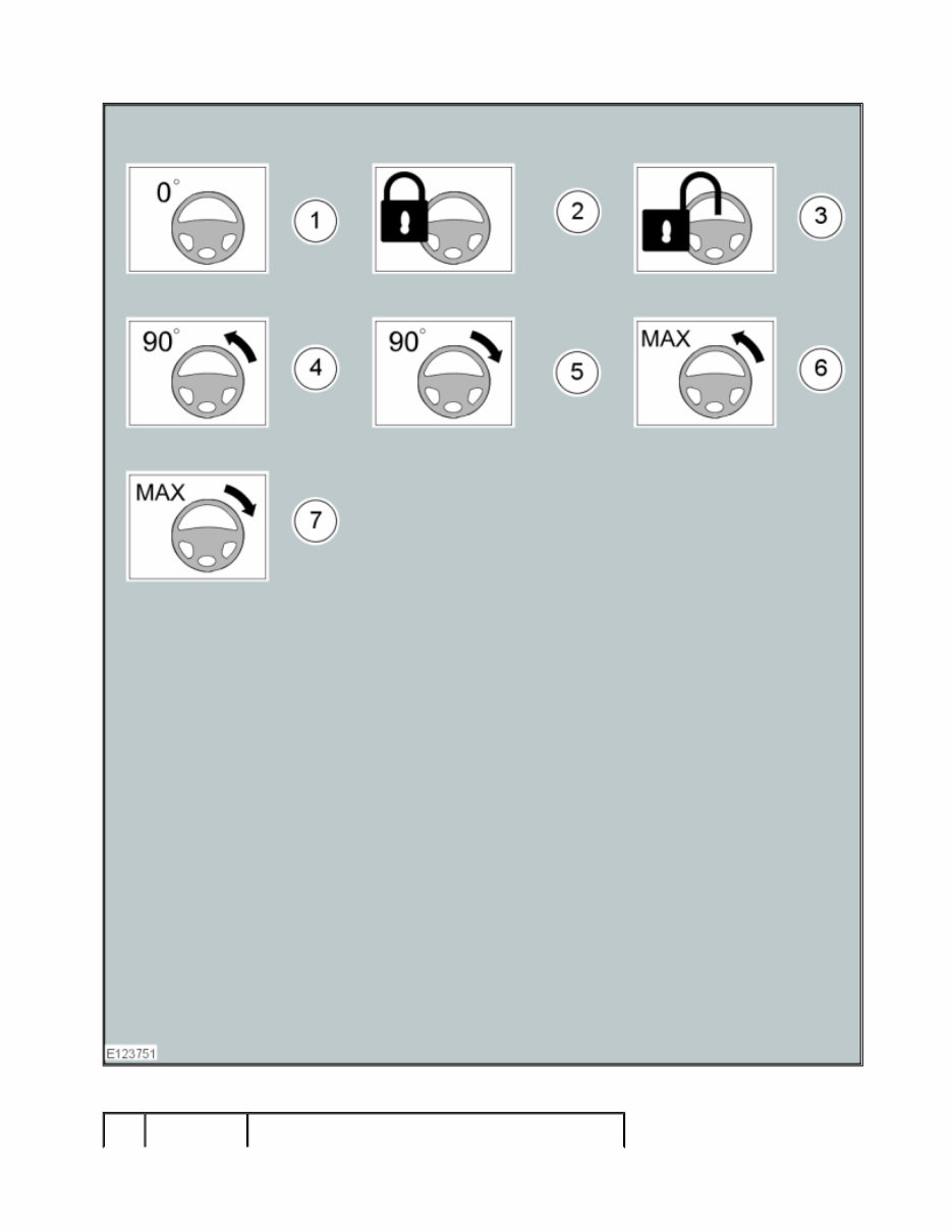
Steering Wheel Symbols Steering wheel symbols are used to provide further information to a required steering wheel position or steering column lock status. turns 8 — Turn the component counterclockwise through 2 complete turns Page 4 of 33 2014-04-30 file://C:\TSO\tsocache\VDTOM_1168\SDZ~us~en~file=SDZG1615041.HTM~gen~ref.... tomsn048@gmail.com
Part Page 5 of 33 2014-04-30 file://C:\TSO\tsocache\VDTOM_1168\SDZ~us~en~file=SDZG1615041.HTM~gen~ref....
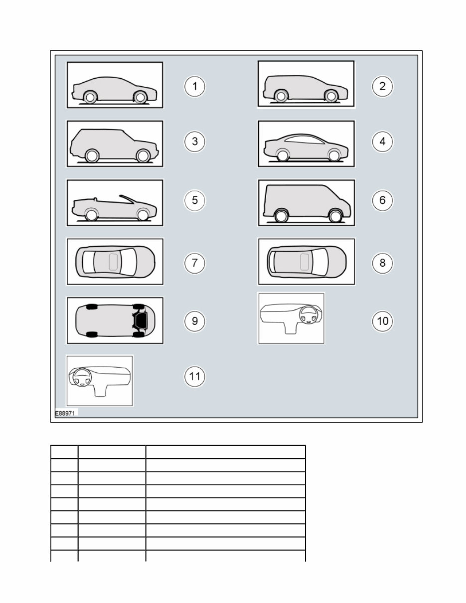
Body Types Body type symbols are used to identify different body configurations. Item Number Description 1 — Steering wheel in straight ahead position 2 — Steering column lock locked 3 — Steering column lock unlocked 4 — Turn the steering wheel to the 90° left position 5 — Turn the steering wheel to the 90° right position 6 — Turn the steering wheel to the left-hand end position 7 — Turn the steering wheel to the right-hand end position Page 6 of 33 2014-04-30 file://C:\TSO\tsocache\VDTOM_1168\SDZ~us~en~file=SDZG1615041.HTM~gen~ref.... tomsn048@gmail.com
Item Part Number Description 1 — 3, 4, 5-door body style 2 — Wagon body style 3 — Sports utility vehicle body style 4 — Coupe body style 5 — Convertible body style 6 — Van body style 7 — 3, 4, 5-door body style - Top View Page 7 of 33 2014-04-30 file://C:\TSO\tsocache\VDTOM_1168\SDZ~us~en~file=SDZG1615041.HTM~gen~ref....
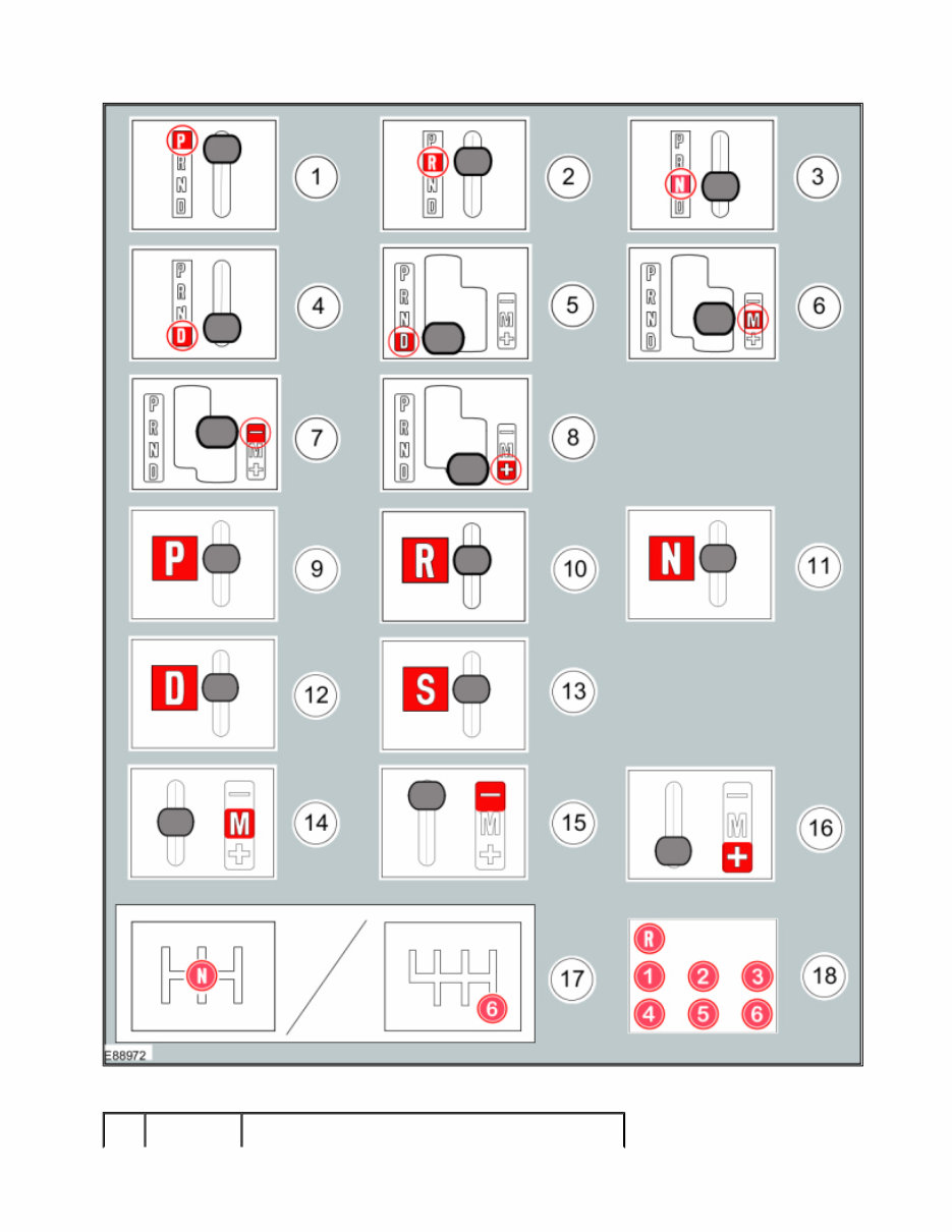
Gearshift lever and selector lever position symbols Gearshift lever and selector lever position symbols are used to show the lever position that is required to be selected to carry out a procedure step. 8 — Wagon body style - Top View 9 — Underview 10 — Right-hand drive (RHD) vehicle 11 — Left-hand drive (LHD) vehicle Page 8 of 33 2014-04-30 file://C:\TSO\tsocache\VDTOM_1168\SDZ~us~en~file=SDZG1615041.HTM~gen~ref.... tomsn048@gmail.com
Part Page 9 of 33 2014-04-30 file://C:\TSO\tsocache\VDTOM_1168\SDZ~us~en~file=SDZG1615041.HTM~gen~ref....
Screwdriver symbols The screwdriver symbols are used to show which screwdriver bit is recommended to carry out a procedure step. Item Number Description 1 — Replaced by symbol 9 2 — Replaced by symbol 10 3 — Replaced by symbol 11 4 — Replaced by symbol 12 5 — Replaced by symbol 12 6 — Replaced by symbol 14 7 — Replaced by symbol 15 8 — Replaced by symbol 16 9 — Set the selector lever to the park (P) position 10 — Set the selector lever to the reverse ( R ) position 11 — Set the selector lever to the neutral (N) position 12 — Set the selector lever to the drive (D) position 13 — Set the selector lever to the drive (S) position 14 — Set the selector lever to the drive (M) position 15 — Set the selector lever to the drive (-) position 16 — Set the selector lever to the drive (+) position 17 — Set the gearshift lever to the neutral (N) position 18 — Further gearshift lever positions that may appear in illustrations Page 10 of 33 2014-04-30 file://C:\TSO\tsocache\VDTOM_1168\SDZ~us~en~file=SDZG1615041.HTM~gen~ref.... tomsn048@gmail.com
Introducing the 2013-2014 Ford Escape Service & Repair Manual, a comprehensive resource for maintaining and repairing your Ford Escape.
This manual is tailored for the 2013-2014 Ford Escape models, offering detailed instructions and diagrams for a wide range of service and repair tasks.
2013 Ford Escape
2014 Ford Escape
It provides valuable information on engine repairs, electrical systems, fuel and exhaust systems, suspension and steering, brakes, transmission, and more. Whether you're a professional mechanic or a DIY enthusiast, this manual is an essential tool for your workshop.
Each section is organized logically, with step-by-step instructions and detailed illustrations to guide you through each procedure. You'll find specifications, diagnostic charts, and troubleshooting tips to help you diagnose and fix any issues with your Ford Escape.
Investing in the 2013-2014 Ford Escape Service & Repair Manual ensures accurate and up-to-date information. Don't rely on generic repair manuals - get the manual specifically designed for your vehicle.
Order your copy of the 2013-2014 Ford Escape Service & Repair Manual today and take control of your vehicle's maintenance and repairs.